2007 ISUZU KB P190 Circuit
[x] Cancel search: CircuitPage 5886 of 6020
IMMOBILIZER CONTROL SYSTEM (4JK1/4JJ1/HFV6) 11A-35
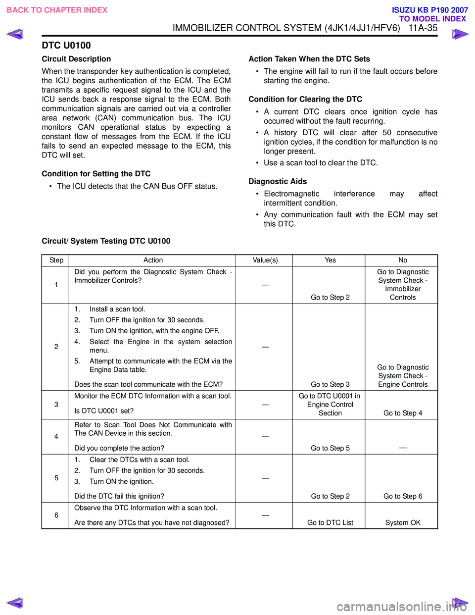
DTC U0100
Circuit Description
When the transponder key authentication is completed,
the ICU begins authentication of the ECM. The ECM
transmits a specific request signal to the ICU and the
ICU sends back a response signal to the ECM. Both
communication signals are carried out via a controller
area network (CAN) communication bus. The ICU
monitors CAN operational status by expecting a
constant flow of messages from the ECM. If the ICU
fails to send an expected message to the ECM, this
DTC will set.
Condition for Setting the DTC • The ICU detects that the CAN Bus OFF status. Action Taken When the DTC Sets
• The engine will fail to run if the fault occurs before starting the engine.
Condition for Clearing the DTC • A current DTC clears once ignition cycle has occurred without the fault recurring.
• A history DTC will clear after 50 consecutive ignition cycles, if the condition for malfunction is no
longer present.
• Use a scan tool to clear the DTC.
Diagnostic Aids • Electromagnetic interference may affect intermittent condition.
• Any communication fault with the ECM may set this DTC.
Circuit/ System Testing DTC U0100
Step Action Value(s)Yes No
1 Did you perform the Diagnostic System Check -
Immobilizer Controls? —
Go to Step 2 Go to Diagnostic
System Check - Immobilizer
Controls
2 1. Install a scan tool.
2. Turn OFF the ignition for 30 seconds.
3. Turn ON the ignition, with the engine OFF.
4. Select the Engine in the system selection menu.
5. Attempt to communicate with the ECM via the Engine Data table.
Does the scan tool communicate with the ECM? —
Go to Step 3 Go to Diagnostic
System Check -
Engine Controls
3 Monitor the ECM DTC Information with a scan tool.
Is DTC U0001 set? —Go to DTC U0001 in
Engine Control Section Go to Step 4
4 Refer to Scan Tool Does Not Communicate with
The CAN Device in this section.
Did you complete the action? —
Go to Step 5
—
51. Clear the DTCs with a scan tool.
2. Turn OFF the ignition for 30 seconds.
3. Turn ON the ignition.
Did the DTC fail this ignition? —
Go to Step 2 Go to Step 6
6 Observe the DTC Information with a scan tool.
Are there any DTCs that you have not diagnosed? —
Go to DTC List System OK
BACK TO CHAPTER INDEX
TO MODEL INDEX
ISUZU KB P190 2007
Page 5899 of 6020
IMMOBILIZER SYSTEM (C24SE, 4JA1-T) 11A-1
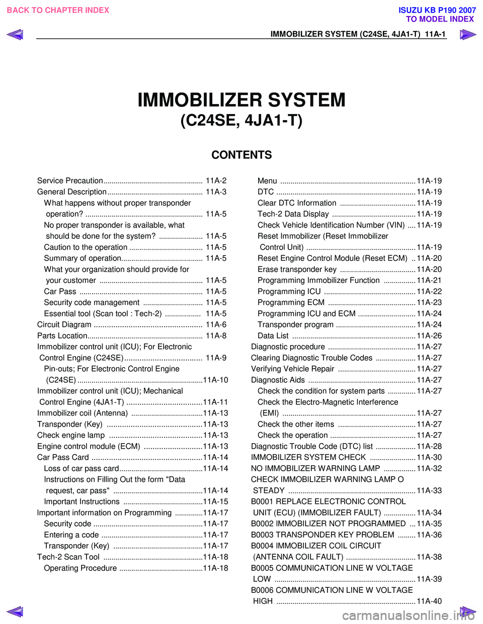
IMMOBILIZER SYSTEM
(C24SE, 4JA1-T)
CONTENTS
Service Precaution .................................................. 11A-2
General Description ................................................ 11A-3
W hat happens without proper transponder
operation? ........................................................... 11A-5
No proper transponder is available, what
should be done for the system? ...................... 11A-5
Caution to the operation ..................................... 11A-5
Summary of operation ......................................... 11A-5
W hat your organization should provide for
your customer .................................................... 11A-5
Car Pass .............................................................. 11A-5
Security code management .............................. 11A-5
Essential tool (Scan tool : Tech-2) .................. 11A-5
Circuit Diagram .................................................. 11A-6
Parts Location .......................................................... 11A-8
Immobilizer control unit (ICU); For Electronic
Control Engine (C24SE) .................................... 11A-9
Pin-outs; For Electronic Control Engine
(C24SE) ............................................................... 11A-10
Immobilizer control unit (ICU); Mechanical
Control Engine (4JA1-T) ...................................11A-11
Immobilizer coil (Antenna) ....................................11A-13
Transponder (Key) ............................................11A-13
Check engine lamp ...........................................11A-13
Engine control module (ECM) ...........................11A-13
Car Pass Card ...................................................11A-14 Loss of car pass card .......................................... 11A-14
Instructions on Filling Out the form "Data
request, car pass" ............................................. 11A-14
Important Instructions ........................................ 11A-15
lmportant information on Programming ..............11A-17
Security code ....................................................... 11A-17
Entering a code ................................................... 11A-17
Transponder (Key) ............................................. 11A-17
Tech-2 Scan Tool .................................................. 11A-18
Operating Procedure .......................................... 11A-18
Menu .................................................................... 11A-19
DTC ...................................................................... 11A-19
Clear DTC Information ......................................11A-19
Tech-2 Data Display .......................................... 11A-19
Check Vehicle Identification Number (VIN) ....11A-19
Reset Immobilizer (Reset Immobilizer
Control Unit) ....................................................... 11A-19
Reset Engine Control Module (Reset ECM) ..11A-20
Erase transponder key ......................................11A-20
Programming Immobilizer Function ................11A-21
Programming ICU .............................................. 11A-22
Programming ECM ............................................ 11A-23
Programming ICU and ECM .............................11A-24
Transponder program ........................................ 11A-24
Data List .............................................................. 11A-26
Diagnostic procedure ............................................ 11A-27
Clearing Diagnostic Trouble Codes ....................11A-27
Verifying Vehicle Repair .......................................11A-27
Diagnostic Aids ...................................................... 11A-27
Check the condition for system parts ..............11A-27
Check the Electro-Magnetic Interference
(EMI) ................................................................... 11A-27
Check the other items .......................................11A-27
Check the operation ........................................... 11A-27
Diagnostic Trouble Code (DTC) list ....................11A-28
IMMOBILIZER SYSTEM CHECK .......................11A-30
NO IMMOBILIZER W ARNING LAMP ................11A-32
CHECK IMMOBILIZER W ARNING LAMP O
STEADY ................................................................ 11A-33
B0001 REPLACE ELECTRONIC CONTROL
UNIT (ECU) (IMMOBILIZER FAULT) ................11A-34
B0002 IMMOBILIZER NOT PROGRAMMED ...11A-35
B0003 TRANSPONDER KEY PROBLEM .........11A-36
B0004 IMMOBILIZER COIL CIRCUIT
(ANTENNA COIL FAULT) ...................................11A-38
B0005 COMMUNICATION LINE W VOLTAGE
LOW ....................................................................... 11A-39
B0006 COMMUNICATION LINE W VOLTAGE
HIGH ...................................................................... 11A-40
BACK TO CHAPTER INDEX
TO MODEL INDEX
ISUZU KB P190 2007
Page 5900 of 6020
11A-2 IMMOBILIZER SYSTEM (C24SE, 4JA1-T)
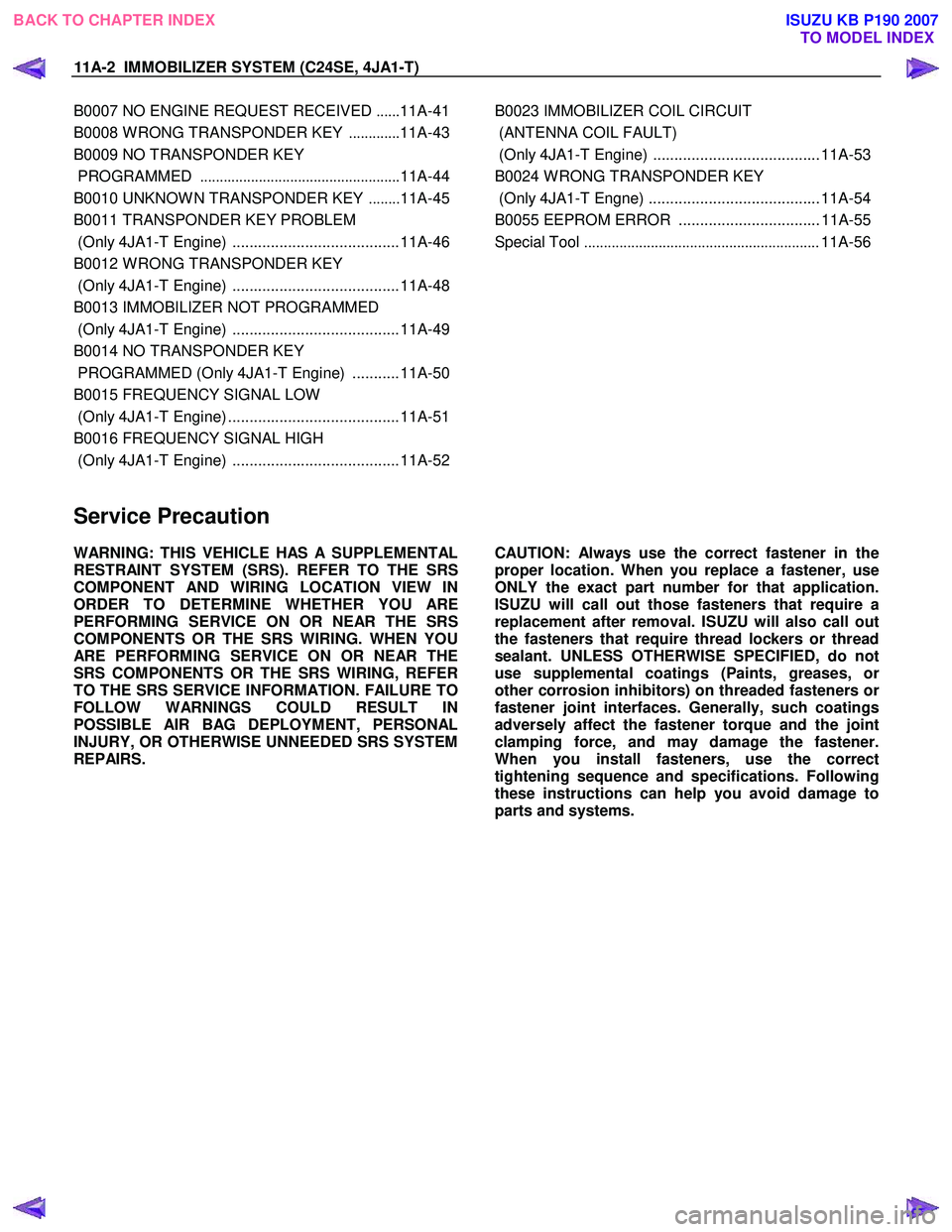
B0007 NO ENGINE REQUEST RECEIVED ......11A-41
B0008 W RONG TRANSPONDER KEY .............11A-43
B0009 NO TRANSPONDER KEY
PROGRAMMED ................................................... 11A-44
B0010 UNKNOW N TRANSPONDER KEY ........11A-45
B0011 TRANSPONDER KEY PROBLEM
(Only 4JA1-T Engine) .......................................11A-46
B0012 W RONG TRANSPONDER KEY
(Only 4JA1-T Engine) .......................................11A-48
B0013 IMMOBILIZER NOT PROGRAMMED
(Only 4JA1-T Engine) .......................................11A-49
B0014 NO TRANSPONDER KEY
PROGRAMMED (Only 4JA1-T Engine) ...........11A-50
B0015 FREQUENCY SIGNAL LOW
(Only 4JA1-T Engine) ........................................11A-51
B0016 FREQUENCY SIGNAL HIGH
(Only 4JA1-T Engine) .......................................11A-52
B0023 IMMOBILIZER COIL CIRCUIT
(ANTENNA COIL FAULT)
(Only 4JA1-T Engine) ....................................... 11A-53
B0024 W RONG TRANSPONDER KEY
(Only 4JA1-T Engne) ........................................ 11A-54
B0055 EEPROM ERROR ................................. 11A-55
Special Tool ............................................................ 11A-56
Service Precaution
WARNING: THIS VEHICLE HAS A SUPPLEMENTAL
RESTRAINT SYSTEM (SRS). REFER TO THE SRS
COMPONENT AND WIRING LOCATION VIEW IN
ORDER TO DETERMINE WHETHER YOU ARE
PERFORMING SERVICE ON OR NEAR THE SRS
COMPONENTS OR THE SRS WIRING. WHEN YOU
ARE PERFORMING SERVICE ON OR NEAR THE
SRS COMPONENTS OR THE SRS WIRING, REFER
TO THE SRS SERVICE INFORMATION. FAILURE TO
FOLLOW WARNINGS COULD RESULT IN
POSSIBLE AIR BAG DEPLOYMENT, PERSONAL
INJURY, OR OTHERWISE UNNEEDED SRS SYSTEM
REPAIRS.
CAUTION: Always use the correct fastener in the
proper location. When you replace a fastener, use
ONLY the exact part number for that application.
ISUZU will call out those fasteners that require a
replacement after removal. ISUZU will also call out
the fasteners that require thread lockers or thread
sealant. UNLESS OTHERWISE SPECIFIED, do not
use supplemental coatings (Paints, greases, o
r
other corrosion inhibitors) on threaded fasteners or
fastener joint interfaces. Generally, such coatings
adversely affect the fastener torque and the joint
clamping force, and may damage the fastener.
When you install fasteners, use the correct
tightening sequence and specifications. Following
these instructions can help you avoid damage to
parts and systems.
BACK TO CHAPTER INDEX
TO MODEL INDEX
ISUZU KB P190 2007
Page 5904 of 6020
11A-6 IMMOBILIZER SYSTEM (C24SE, 4JA1-T)
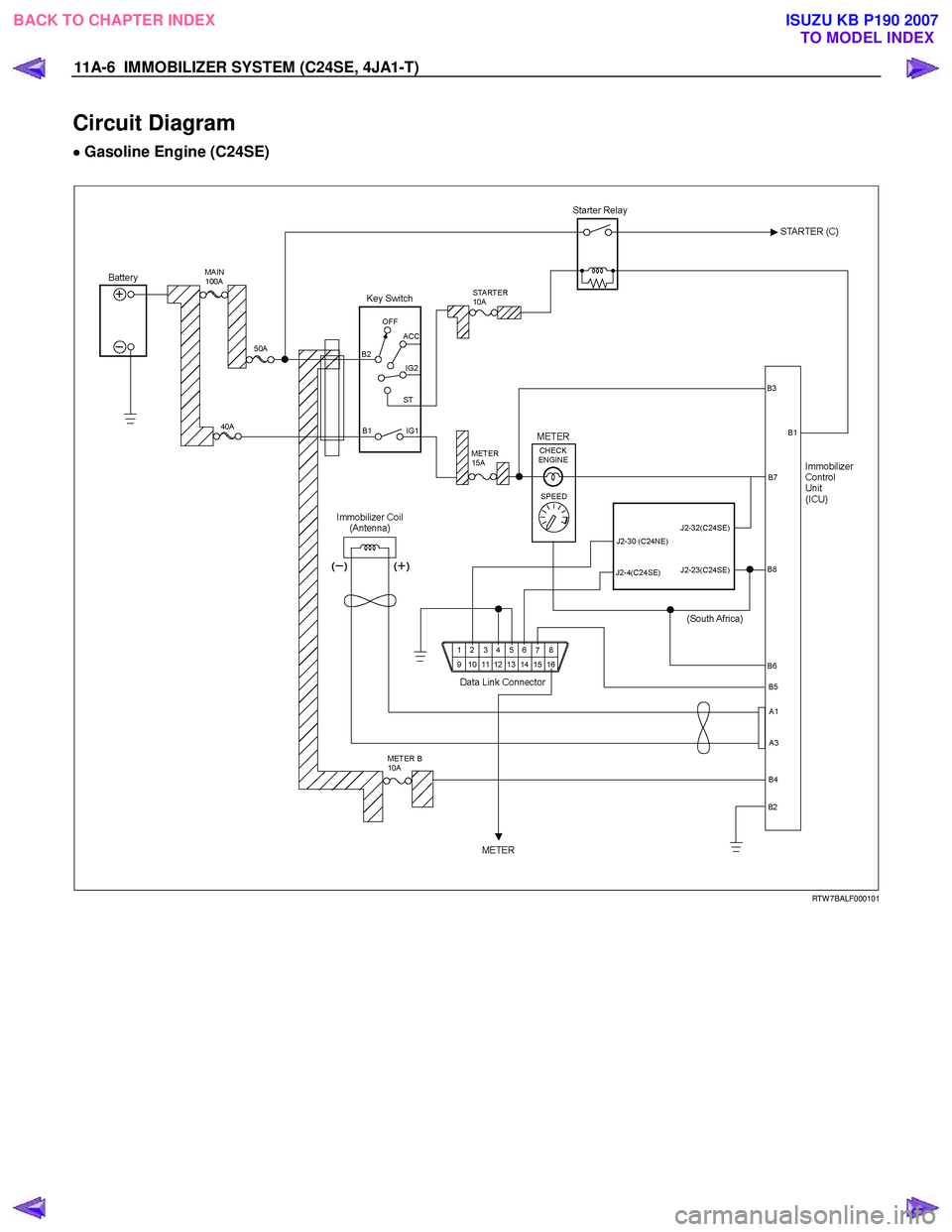
Circuit Diagram
•
••
•
Gasoline Engine (C24SE)
RTW 7BALF000101
BACK TO CHAPTER INDEX TO MODEL INDEX
ISUZU KB P190 2007
Page 5926 of 6020
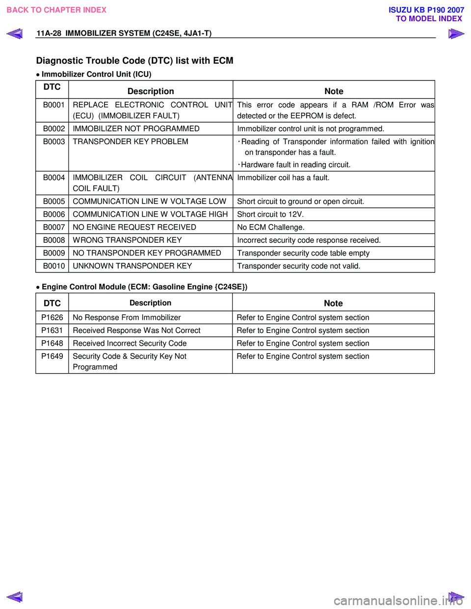
11A-28 IMMOBILIZER SYSTEM (C24SE, 4JA1-T)
Diagnostic Trouble Code (DTC) list with ECM
•
••
•
Immobilizer Control Unit (ICU)
DTC
Description Note
B0001 REPLACE ELECTRONIC CONTROL UNIT
(ECU) (IMMOBILIZER FAULT) This error code appears if a RAM /ROM Error was
detected or the EEPROM is defect.
B0002 IMMOBILIZER NOT PROGRAMMED Immobilizer control unit is not programmed.
B0003 TRANSPONDER KEY PROBLEM ・Reading of Transponder information failed with ignition
on transponder has a fault.
・Hardware fault in reading circuit.
B0004 IMMOBILIZER COIL CIRCUIT (ANTENNA
COIL FAULT) Immobilizer coil has a fault.
B0005 COMMUNICATION LINE W VOLTAGE LOW Short circuit to ground or open circuit.
B0006 COMMUNICATION LINE W VOLTAGE HIGH Short circuit to 12V.
B0007 NO ENGINE REQUEST RECEIVED
No ECM Challenge.
B0008 W RONG TRANSPONDER KEY Incorrect security code response received.
B0009 NO TRANSPONDER KEY PROGRAMMED Transponder security code table empty
B0010 UNKNOW N TRANSPONDER KEY Transponder security code not valid.
•
••
•
Engine Control Module (ECM: Gasoline Engine {C24SE})
DTC Description
Note
P1626 No Response From Immobilizer Refer to Engine Control system section
P1631 Received Response W as Not Correct Refer to Engine Control system section
P1648 Received Incorrect Security Code Refer to Engine Control system section
P1649 Security Code & Security Key Not
Programmed Refer to Engine Control system section
BACK TO CHAPTER INDEX TO MODEL INDEX
ISUZU KB P190 2007
Page 5928 of 6020
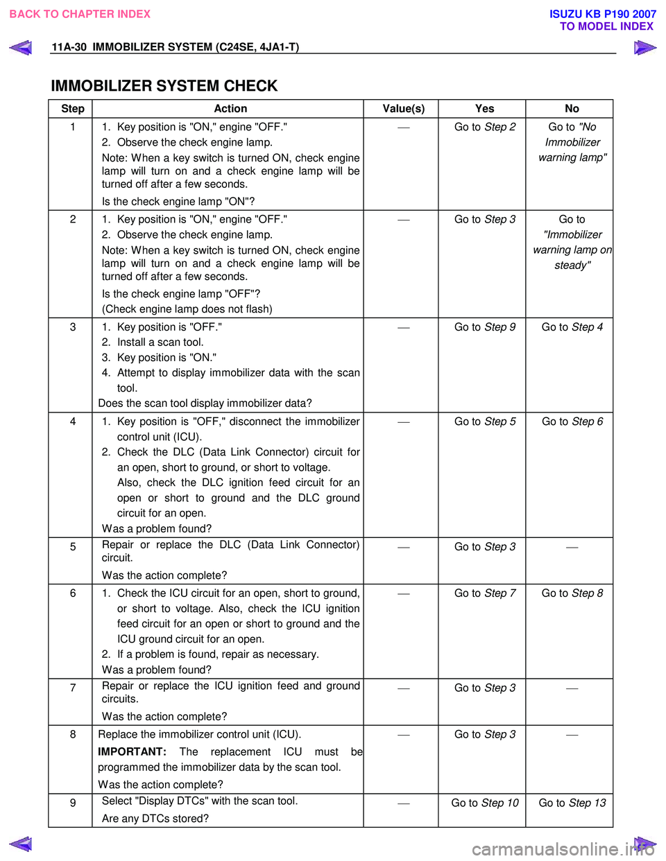
11A-30 IMMOBILIZER SYSTEM (C24SE, 4JA1-T)
IMMOBILIZER SYSTEM CHECK
Step Action Value(s) Yes No
1 1. Key position is "ON," engine "OFF."
2. Observe the check engine lamp.
Note: W hen a key switch is turned ON, check engine
lamp will turn on and a check engine lamp will be
turned off after a few seconds.
Is the check engine lamp "ON"?
Go to Step 2 Go to "No
Immobilizer
warning lamp"
2 1. Key position is "ON," engine "OFF." 2. Observe the check engine lamp.
Note: W hen a key switch is turned ON, check engine
lamp will turn on and a check engine lamp will be
turned off after a few seconds.
Is the check engine lamp "OFF"?
(Check engine lamp does not flash)
Go to Step 3 Go to
"Immobilizer
warning lamp on steady"
3 1. Key position is "OFF."
2. Install a scan tool.
3. Key position is "ON."
4. Attempt to display immobilizer data with the scan tool.
Does the scan tool display immobilizer data?
Go to Step 9 Go to Step 4
4 1. Key position is "OFF," disconnect the immobilizer
control unit (ICU).
2. Check the DLC (Data Link Connector) circuit for an open, short to ground, or short to voltage.
Also, check the DLC ignition feed circuit for an open or short to ground and the DLC ground
circuit for an open.
W as a problem found?
Go to Step 5 Go to Step 6
5 Repair or replace the DLC (Data Link Connector)
circuit.
W as the action complete?
Go to Step 3
6 1. Check the ICU circuit for an open, short to ground,
or short to voltage. Also, check the ICU ignition
feed circuit for an open or short to ground and the
ICU ground circuit for an open.
2. If a problem is found, repair as necessary.
W as a problem found?
Go to Step 7 Go to Step 8
7 Repair or replace the ICU ignition feed and ground
circuits.
W as the action complete?
Go to Step 3
8 Replace the immobilizer control unit (ICU).
IMPORTANT: The replacement ICU must be
programmed the immobilizer data by the scan tool.
W as the action complete?
Go to Step 3
9 Select "Display DTCs" with the scan tool.
Are any DTCs stored?
Go to Step 10 Go to Step 13
BACK TO CHAPTER INDEX
TO MODEL INDEX
ISUZU KB P190 2007
Page 5930 of 6020
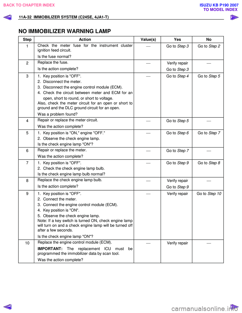
11A-32 IMMOBILIZER SYSTEM (C24SE, 4JA1-T)
NO IMMOBILIZER WARNING LAMP
Step Action Value(s) Yes No
1 Check the meter fuse for the instrument cluster
ignition feed circuit.
Is the fuse normal?
Go to Step 3 Go to Step 2
2 Replace the fuse.
Is the action complete?
Verify repair
Go to Step 3
3 1. Key position is "OFF".
2. Disconnect the meter.
3. Disconnect the engine control module (ECM).
4. Check the circuit between meter and ECM for an open, short to round, or short to voltage.
Also, check the meter circuit for an open or short to
ground and the DLC ground circuit for an open.
W as a problem found?
Go to Step 4 Go to Step 5
4 Repair or replace the meter circuit.
W as the action complete?
Go to Step 5
5 1. Key position is "ON," engine "OFF."
2. Observe the check engine lamp.
Is the check engine lamp "ON"?
Go to Step 6 Go to Step 7
6 Repair or replace the meter.
W as the action complete?
Go to Step 7
7 1. Key position is "OFF".
2. Check the check engine lamp bulb.
Is the check engine lamp bulb normal?
Go to Step 9 Go to Step 8
8 Replace the check engine lamp bulb.
Is the action complete?
Verify repair
Go to Step 9
9 1. Key position is "OFF".
2. Connect the meter.
3. Connect the engine control module (ECM).
4. Key position is "ON".
5. Observe the check engine lamp.
Note: If a key switch is turned ON, check engine lamp
will turn on and a check engine lamp will be turned off
after a few seconds.
Is the check engine lamp "ON"?
Verify repair Go to Step 10
10 Replace the engine control module (ECM).
IMPORTANT: The replacement ICU must be
programmed the immobilizer data by scan tool.
W as the action complete?
Verify repair
BACK TO CHAPTER INDEX TO MODEL INDEX
ISUZU KB P190 2007
Page 5931 of 6020
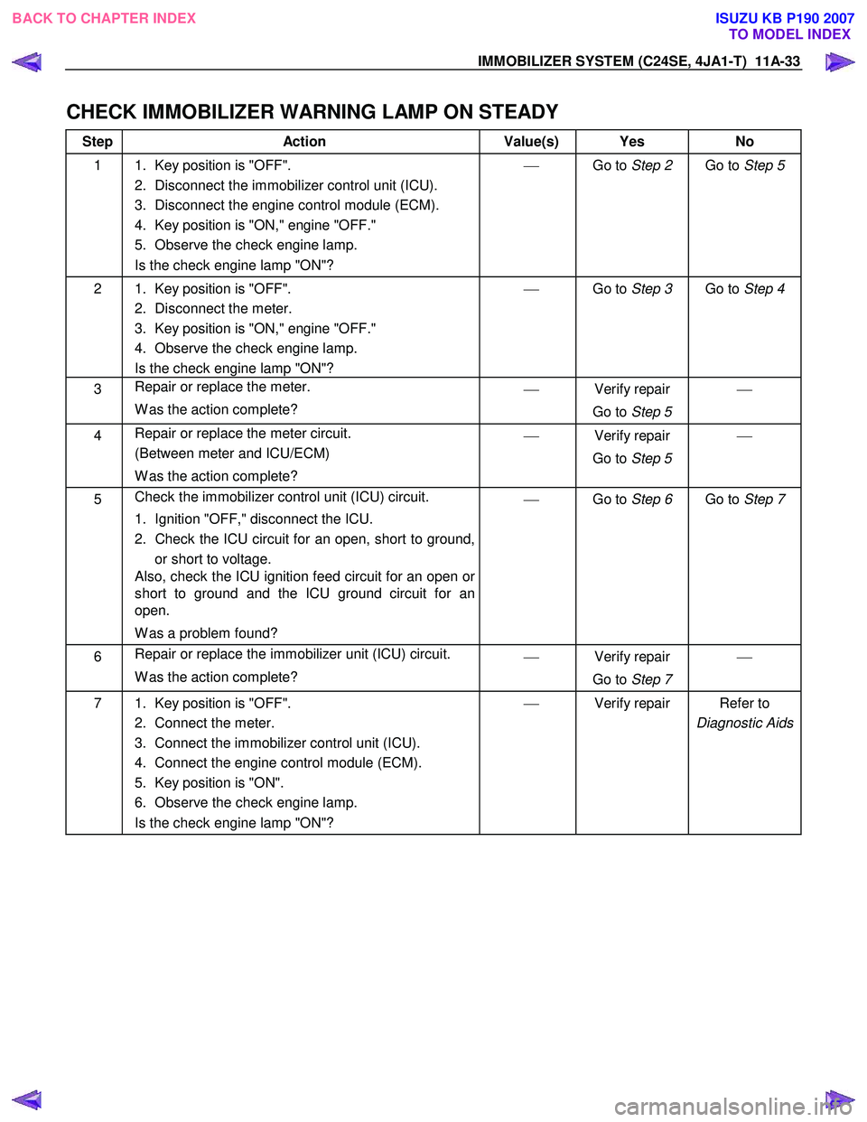
IMMOBILIZER SYSTEM (C24SE, 4JA1-T) 11A-33
CHECK IMMOBILIZER WARNING LAMP ON STEADY
Step Action Value(s) Yes No
1 1. Key position is "OFF".
2. Disconnect the immobilizer control unit (ICU).
3. Disconnect the engine control module (ECM).
4. Key position is "ON," engine "OFF."
5. Observe the check engine lamp.
Is the check engine lamp "ON"?
Go to Step 2 Go to Step 5
2 1. Key position is "OFF".
2. Disconnect the meter.
3. Key position is "ON," engine "OFF."
4. Observe the check engine lamp.
Is the check engine lamp "ON"?
Go to Step 3 Go to Step 4
3 Repair or replace the meter.
W as the action complete?
Verify repair
Go to Step 5
4 Repair or replace the meter circuit.
(Between meter and ICU/ECM)
W as the action complete?
Verify repair
Go to Step 5
5 Check the immobilizer control unit (ICU) circuit.
1. Ignition "OFF," disconnect the ICU.
2. Check the ICU circuit for an open, short to ground, or short to voltage.
Also, check the ICU ignition feed circuit for an open or
short to ground and the ICU ground circuit for an
open.
W as a problem found?
Go to Step 6 Go to Step 7
6 Repair or replace the immobilizer unit (ICU) circuit.
W as the action complete?
Verify repair
Go to Step 7
7 1. Key position is "OFF".
2. Connect the meter.
3. Connect the immobilizer control unit (ICU).
4. Connect the engine control module (ECM).
5. Key position is "ON".
6. Observe the check engine lamp.
Is the check engine lamp "ON"?
Verify repair Refer to
Diagnostic Aids
BACK TO CHAPTER INDEX TO MODEL INDEX
ISUZU KB P190 2007