2007 ISUZU KB P190 diagram
[x] Cancel search: diagramPage 3787 of 6020
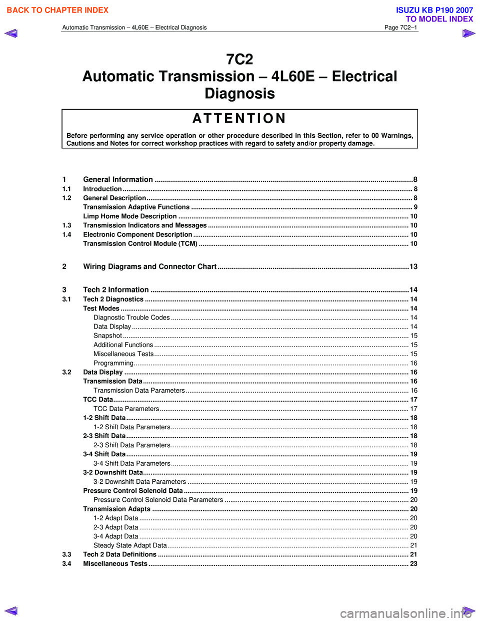
Automatic Transmission – 4L60E – Electrical Diagnosis Page 7C2–1
7C2
Diagnosis
ATTENTION
Before performing any service operation or other procedure described in this Section, refer to 00 Warnings, Cautions and Notes for correct workshop practices with regard to safety and/or property damage.
1 General Information ............................................................................................................ ...................8
1.1 Introduction ............................................................................................................................................................ 8
1.2 General Description ............................................................................................................................................... 8
Transmission Adaptive Functions ................................................................................................ ....................... 9
Limp Home Mode Description ............................................................................................................................ 10
1.3 Transmission Indicators and Messages ............................................................................................................ 10
1.4 Electronic Component Description ............................................................................................... ..................... 10
Transmission Control Module (TCM) ................................................................................................................. 10
2 Wiring Diagrams and Connector Chart ............................................................................................ ..13
3 Tech 2 Information ...............................................................................................................................14
3.1 Tech 2 Diagnostics .............................................................................................................................................. 14
Test Modes ........................................................................................................................................................... 14
Diagnostic Trouble Codes ....................................................................................................... ......................... 14
Data Display ..................................................................................................................................................... 14
Snapshot .......................................................................................................................................................... 15
Additional Functions ........................................................................................................... .............................. 15
Miscellaneous Tests ......................................................................................................................................... 15
Programming.................................................................................................................................................... 16
3.2 Data Display ......................................................................................................................................................... 16
Transmission Data .............................................................................................................. ................................. 16
Transmission Data Parameters ................................................................................................... ..................... 16
TCC Data............................................................................................................................................................... 17
TCC Data Parameters ............................................................................................................ .......................... 17
1-2 Shift Data ........................................................................................................................................................ 18
1-2 Shift Data Parameters ................................................................................................................................ 18
2-3 Shift Data ........................................................................................................................................................ 18
2-3 Shift Data Parameters ................................................................................................................................ 18
3-4 Shift Data ........................................................................................................................................................ 19
3-4 Shift Data Parameters ................................................................................................................................ 19
3-2 Downshift Data............................................................................................................................................... 19
3-2 Downshift Data Parameters ....................................................................................................................... 19
Pressure Control Solenoid Data ................................................................................................. ........................ 19
Pressure Control Solenoid Data Parameters ...................................................................................... ............. 20
Transmission Adapts .......................................................................................................................................... 20
1-2 Adapt Data ................................................................................................................................................. 20
2-3 Adapt Data ................................................................................................................................................. 20
3-4 Adapt Data ................................................................................................................................................. 20
Steady State Adapt Data ........................................................................................................ .......................... 21
3.3 Tech 2 Data Definitions ........................................................................................................ ............................... 21
3.4 Miscellaneous Tests ............................................................................................................................................ 23
Automatic Tra nsm ission – 4L60E – Electric al
BACK TO CHAPTER INDEX
TO MODEL INDEX
ISUZU KB P190 2007
Page 3799 of 6020
Automatic Transmission – 4L60E – Electrical Diagnosis Page 7C2–13
2 Wiring Diagrams and Connector
Chart
For wiring diagrams and connector information, refer to 8A Electrica-Body and Chassis.
BACK TO CHAPTER INDEX
TO MODEL INDEX
ISUZU KB P190 2007
Page 3819 of 6020
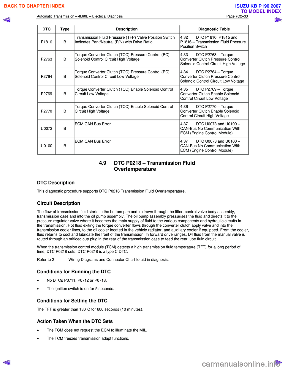
Automatic Transmission – 4L60E – Electrical Diagnosis Page 7C2–33
DTC Type Description Diagnostic Table
P1816 B Transmission Fluid Pressure (TFP) Valve Position Switch
Indicates Park/Neutral (P/N) with Drive Ratio 4.32 DTC P1810, P1815 and
P1816 – Transmission Fluid Pressure
Position Switch
P2763 B Torque Converter Clutch (TCC) Pressure Control (PC)
Solenoid Control Circuit High Voltage 4.33 DTC P2763 – Torque
Converter Clutch Pressure Control
Solenoid Control Circuit High Voltage
P2764 B Torque Converter Clutch (TCC) Pressure Control (PC)
Solenoid Control Circuit Low Voltage 4.34 DTC P2764 – Torque
Converter Clutch Pressure Control
Solenoid Control Circuit Low Voltage
P2769 B Torque Converter Clutch (TCC) Enable Solenoid Control
Circuit Low Voltage 4.35 DTC P2769 – Torque
Converter Clutch Enable Solenoid
Control Circuit Low Voltage
P2770 B Torque Converter Clutch (TCC) Enable Solenoid Control
Circuit High Voltage 4.36 DTC P2770 – Torque
Converter Clutch Enable Solenoid
Control Circuit High Voltage
U0073 B ECM CAN Bus Error
4.37 DTC U0073 and U0100 –
CAN-Bus No Communication With
ECM (Engine Control Module)
U0100 B ECM CAN Bus Error
4.37 DTC U0073 and U0100 –
CAN-Bus No Communication With
ECM (Engine Control Module)
4.9 DTC P0218 – Transmission Fluid Overtemperature
DTC Description
This diagnostic procedure supports DTC P0218 Transmission Fluid Overtemperature.
Circuit Description
The flow of transmission fluid starts in the bottom pan and is drawn through the filter, control valve body assembly,
transmission case and into the oil pump assembly. The oil pump assembly pressurises the fluid and directs it to the
pressure regulator valve where it becomes the main supply of fluid to the various components and hydraulic circuits in
the transmission. Hot fluid exiting the torque converter flows through the converter clutch apply valve and into the
transmission cooler lines, to the oil cooler located in the vehicle radiator, and auxiliary cooler if equipped. From the cooler ,
fluid returns to cool and lubricate the front of the transmission. In forward drive ranges, D4 fluid from the manual valve is
routed through an orificed cup plug in the rear of the transmission case to feed the rear lube fluid circuit.
When the transmission control module (TCM) detects a high transmission fluid temperature (TFT) for a long period of
time, DTC P0218 sets. DTC P0218 is a type C DTC.
Refer to 2 W iring Diagrams and Connector Chart to aid in diagnosis.
Conditions for Running the DTC
• No DTCs P0711, P0712 or P0713.
• The ignition switch is on for 5 seconds.
Conditions for Setting the DTC
The TFT is greater than 130°C for 600 seconds (10 minutes).
Action Taken When the DTC Sets
•
The TCM does not request the ECM to illuminate the MIL.
• The TCM freezes transmission adapt functions.
BACK TO CHAPTER INDEX
TO MODEL INDEX
ISUZU KB P190 2007
Page 3822 of 6020
Automatic Transmission – 4L60E – Electrical Diagnosis Page 7C2–36
When the TCM detects low voltage, DTC P0562 sets. DTC P0562 is a type C DTC.
Refer to 2 W iring Diagrams and Connector Chart to aid in diagnosis.
Conditions for Running the DTC
The engine speed is greater than 1,200 r.p.m.
Conditions for Setting the DTC
The TCM detects system voltage less than 11 V for 10 seconds.
Action Taken When the DTC Sets
• The TCM does not request the engine control module (ECM) to illuminate the MIL.
• The TCM records the operating conditions when the conditions for setting the DTC are met. The TCM records this
information as a Failure Record.
• The TCM stores DTC P0562 in TCM history.
Conditions for Clearing the DTC
• The TCM clears the DTC from TCM history if the vehicle completes 40 warm-up cycles without a non-emission
related diagnostic fault occurring.
• Tech 2 can clear the DTC.
Diagnostic Aids
• Observe the instrument cluster’s multi-function display messaging that would indicate the electrical system requires
service.
• Inspect for the following conditions:
• Loose or damaged terminals at the generator, and
• Loose or worn generator drive belt.
Test Description
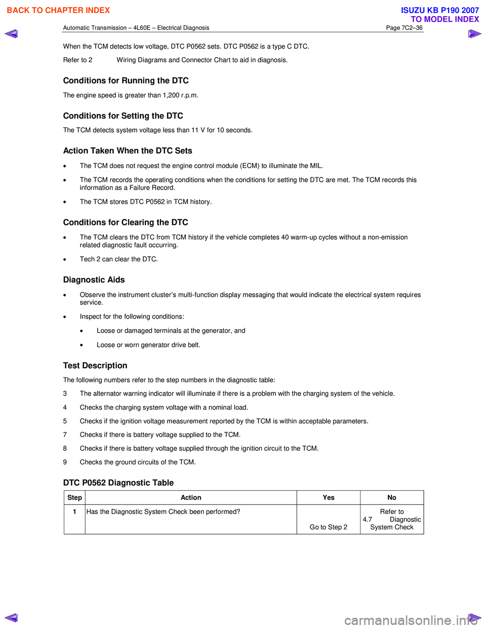
The following numbers refer to the step numbers in the diagnostic table:
3 The alternator warning indicator will illuminate if there is a problem with the charging system of the vehicle.
4 Checks the charging system voltage with a nominal load.
5 Checks if the ignition voltage measurement reported by the TCM is within acceptable parameters.
7 Checks if there is battery voltage supplied to the TCM.
8 Checks if there is battery voltage supplied through the ignition circuit to the TCM.
9 Checks the ground circuits of the TCM.
DTC P0562 Diagnostic Table
Step Action Yes No
1 Has the Diagnostic System Check been performed?
Go to Step 2 Refer to
4.7 Diagnostic
System Check
BACK TO CHAPTER INDEX
TO MODEL INDEX
ISUZU KB P190 2007
Page 3824 of 6020
Automatic Transmission – 4L60E – Electrical Diagnosis Page 7C2–38
Step Action Yes No
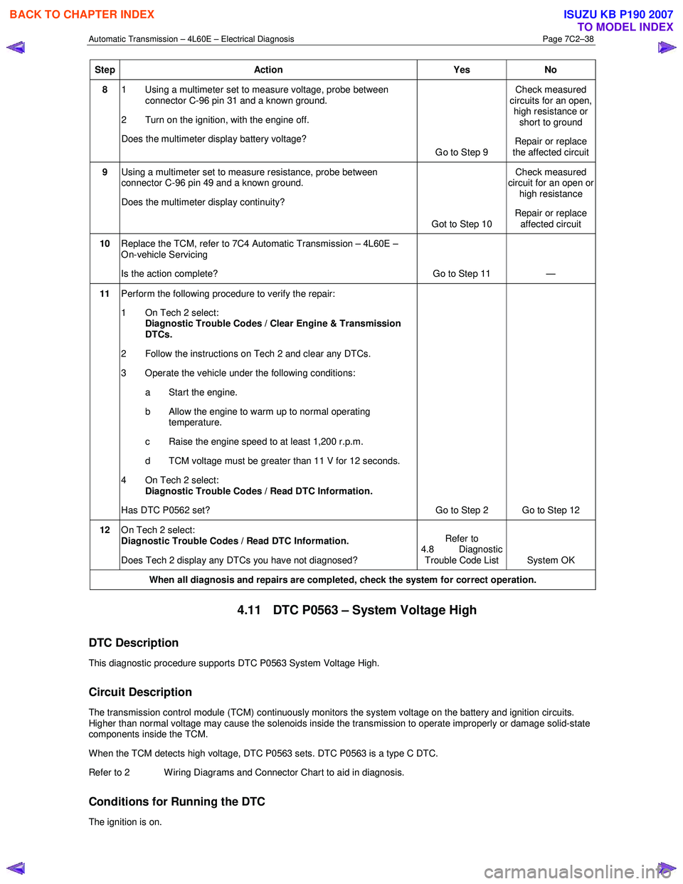
8 1 Using a multimeter set to measure voltage, probe between
connector C-96 pin 31 and a known ground.
2 Turn on the ignition, with the engine off.
Does the multimeter display battery voltage? Go to Step 9 Check measured
circuits for an open, high resistance or short to ground
Repair or replace
the affected circuit
9 Using a multimeter set to measure resistance, probe between
connector C-96 pin 49 and a known ground.
Does the multimeter display continuity?
Got to Step 10 Check measured
circuit for an open or
high resistance
Repair or replace affected circuit
10 Replace the TCM, refer to 7C4 Automatic Transmission – 4L60E –
On-vehicle Servicing
Is the action complete? Go to Step 11 —
11 Perform the following procedure to verify the repair:
1 On Tech 2 select: Diagnostic Trouble Codes / Clear Engine & Transmission
DTCs.
2 Follow the instructions on Tech 2 and clear any DTCs.
3 Operate the vehicle under the following conditions: a Start the engine.
b Allow the engine to warm up to normal operating temperature.
c Raise the engine speed to at least 1,200 r.p.m.
d TCM voltage must be greater than 11 V for 12 seconds.
4 On Tech 2 select: Diagnostic Trouble Codes / Read DTC Information.
Has DTC P0562 set? Go to Step 2 Go to Step 12
12 On Tech 2 select:
Diagnostic Trouble Codes / Read DTC Information.
Does Tech 2 display any DTCs you have not diagnosed? Refer to
4.8 Diagnostic
Trouble Code List System OK
When all diagnosis and repairs are completed, check the
system for correct operation.
4.11 DTC P0563 – System Voltage High
DTC Description
This diagnostic procedure supports DTC P0563 System Voltage High.
Circuit Description
The transmission control module (TCM) continuously monitors the system voltage on the battery and ignition circuits.
Higher than normal voltage may cause the solenoids inside the transmission to operate improperly or damage solid-state
components inside the TCM.
W hen the TCM detects high voltage, DTC P0563 sets. DTC P0563 is a type C DTC.
Refer to 2 W iring Diagrams and Connector Chart to aid in diagnosis.
Conditions for Running the DTC
The ignition is on.
BACK TO CHAPTER INDEX
TO MODEL INDEX
ISUZU KB P190 2007
Page 3827 of 6020
Automatic Transmission – 4L60E – Electrical Diagnosis Page 7C2–41
Step Action Yes No
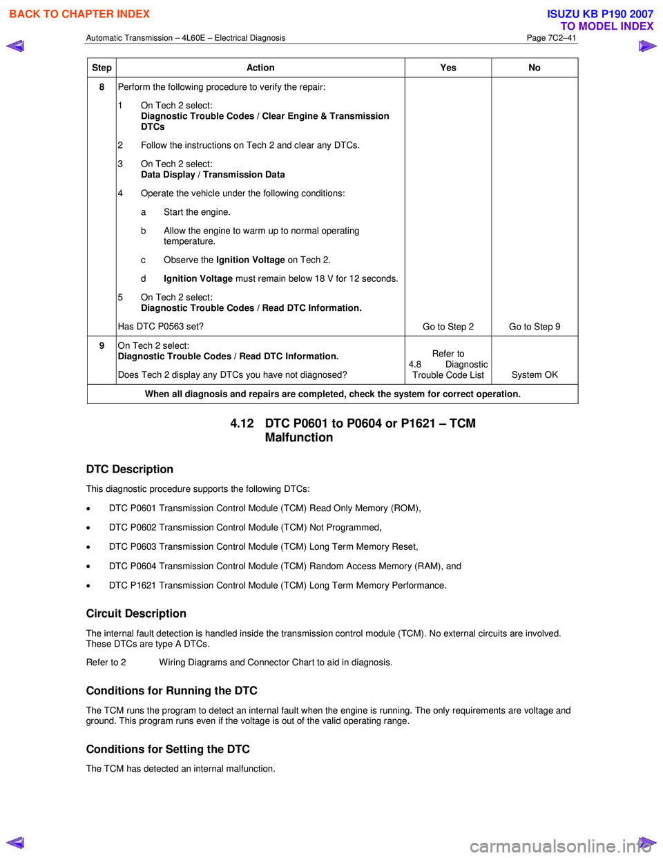
8 Perform the following procedure to verify the repair:
1 On Tech 2 select: Diagnostic Trouble Codes / Clear Engine & Transmission
DTCs
2 Follow the instructions on Tech 2 and clear any DTCs.
3 On Tech 2 select: Data Display / Transmission Data
4 Operate the vehicle under the following conditions: a Start the engine.
b Allow the engine to warm up to normal operating temperature.
c Observe the Ignition Voltage on Tech 2.
d Ignition Voltage must remain below 18 V for 12 seconds.
5 On Tech 2 select:
Diagnostic Trouble Codes / Read DTC Information.
Has DTC P0563 set? Go to Step 2 Go to Step 9
9 On Tech 2 select:
Diagnostic Trouble Codes / Read DTC Information.
Does Tech 2 display any DTCs you have not diagnosed? Refer to
4.8 Diagnostic Trouble Code List System OK
When all diagnosis and repairs are completed, check the
system for correct operation.
4.12 DTC P0601 to P0604 or P1621 – TCM
Malfunction
DTC Description
This diagnostic procedure supports the following DTCs:
• DTC P0601 Transmission Control Module (TCM) Read Only Memory (ROM),
• DTC P0602 Transmission Control Module (TCM) Not Programmed,
• DTC P0603 Transmission Control Module (TCM) Long Term Memory Reset,
• DTC P0604 Transmission Control Module (TCM) Random Access Memory (RAM), and
• DTC P1621 Transmission Control Module (TCM) Long Term Memory Performance.
Circuit Description
The internal fault detection is handled inside the transmission control module (TCM). No external circuits are involved.
These DTCs are type A DTCs.
Refer to 2 W iring Diagrams and Connector Chart to aid in diagnosis.
Conditions for Running the DTC
The TCM runs the program to detect an internal fault when the engine is running. The only requirements are voltage and
ground. This program runs even if the voltage is out of the valid operating range.
Conditions for Setting the DTC
The TCM has detected an internal malfunction.
BACK TO CHAPTER INDEX
TO MODEL INDEX
ISUZU KB P190 2007
Page 3829 of 6020
Automatic Transmission – 4L60E – Electrical Diagnosis Page 7C2–43
Step Action Yes No
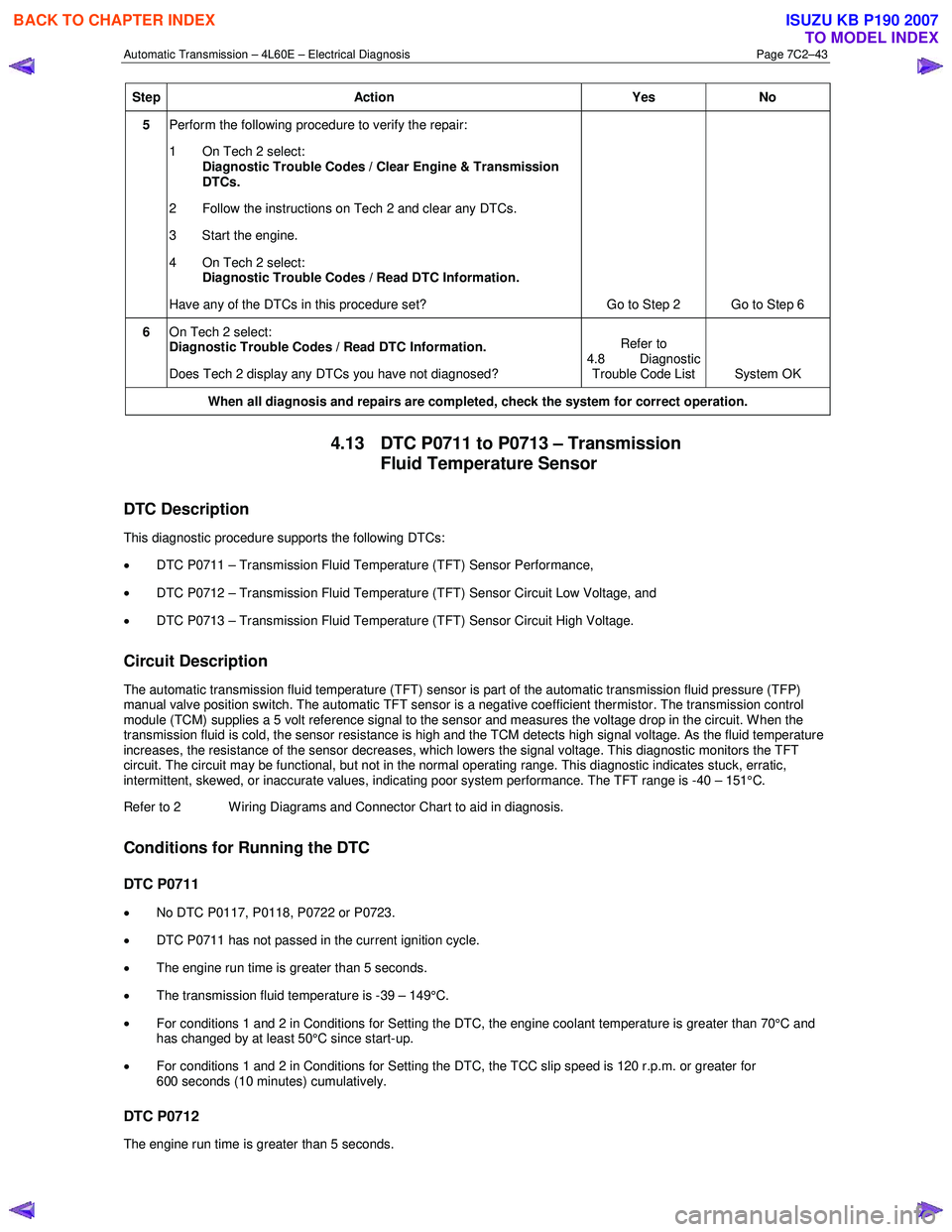
5 Perform the following procedure to verify the repair:
1 On Tech 2 select: Diagnostic Trouble Codes / Clear Engine & Transmission
DTCs.
2 Follow the instructions on Tech 2 and clear any DTCs.
3 Start the engine.
4 On Tech 2 select:
Diagnostic Trouble Codes / Read DTC Information.
Have any of the DTCs in this procedure set? Go to Step 2 Go to Step 6
6 On Tech 2 select:
Diagnostic Trouble Codes / Read DTC Information.
Does Tech 2 display any DTCs you have not diagnosed? Refer to
4.8 Diagnostic Trouble Code List System OK
When all diagnosis and repairs are completed, check the
system for correct operation.
4.13 DTC P0711 to P0713 – Transmission
Fluid Temperature Sensor
DTC Description
This diagnostic procedure supports the following DTCs:
• DTC P0711 – Transmission Fluid Temperature (TFT) Sensor Performance,
• DTC P0712 – Transmission Fluid Temperature (TFT) Sensor Circuit Low Voltage, and
• DTC P0713 – Transmission Fluid Temperature (TFT) Sensor Circuit High Voltage.
Circuit Description
The automatic transmission fluid temperature (TFT) sensor is part of the automatic transmission fluid pressure (TFP)
manual valve position switch. The automatic TFT sensor is a negative coefficient thermistor. The transmission control
module (TCM) supplies a 5 volt reference signal to the sensor and measures the voltage drop in the circuit. W hen the
transmission fluid is cold, the sensor resistance is high and the TCM detects high signal voltage. As the fluid temperature
increases, the resistance of the sensor decreases, which lowers the signal voltage. This diagnostic monitors the TFT
circuit. The circuit may be functional, but not in the normal operating range. This diagnostic indicates stuck, erratic,
intermittent, skewed, or inaccurate values, indicating poor system performance. The TFT range is -40 – 151°C.
Refer to 2 W iring Diagrams and Connector Chart to aid in diagnosis.
Conditions for Running the DTC
DTC P0711
• No DTC P0117, P0118, P0722 or P0723.
• DTC P0711 has not passed in the current ignition cycle.
• The engine run time is greater than 5 seconds.
• The transmission fluid temperature is -39 – 149°C.
• For conditions 1 and 2 in Conditions for Setting the DTC, the engine coolant temperature is greater than 70°C and
has changed by at least 50°C since start-up.
• For conditions 1 and 2 in Conditions for Setting the DTC, the TCC slip speed is 120 r.p.m. or greater for
600 seconds (10 minutes) cumulatively.
DTC P0712
The engine run time is greater than 5 seconds.
BACK TO CHAPTER INDEX
TO MODEL INDEX
ISUZU KB P190 2007
Page 3833 of 6020
Automatic Transmission – 4L60E – Electrical Diagnosis Page 7C2–47
Step Action Yes No
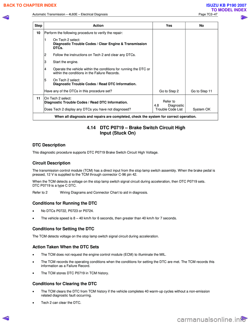
10 Perform the following procedure to verify the repair:
1 On Tech 2 select: Diagnostic Trouble Codes / Clear Engine & Transmission
DTCs.
2 Follow the instructions on Tech 2 and clear any DTCs.
3 Start the engine.
4 Operate the vehicle within the conditions for running the DTC or within the conditions in the Failure Records.
5 On Tech 2 select:
Diagnostic Trouble Codes / Read DTC Information.
Have any of the DTCs in this procedure set? Go to Step 2 Go to Step 11
11 On Tech 2 select:
Diagnostic Trouble Codes / Read DTC Information.
Does Tech 2 display any DTCs you have not diagnosed? Refer to
4.8 Diagnostic Trouble Code List System OK
When all diagnosis and repairs are completed, check the
system for correct operation.
4.14 DTC P0719 – Brake Switch Circuit High
Input (Stuck On)
DTC Description
This diagnostic procedure supports DTC P0719 Brake Switch Circuit High Voltage.
Circuit Description
The transmission control module (TCM) has a direct input from the stop lamp switch assembly. W hen the brake pedal is
pressed, 12 V is supplied to the TCM through connector C-96 pin 42.
W hen the TCM detects a voltage on the stop lamp switch signal circuit during acceleration, then DTC P0719 sets.
DTC P0719 is a type C DTC.
Refer to 2 W iring Diagrams and Connector Chart to aid in diagnosis.
Conditions for Running the DTC
• No DTCs P0722, P0723 or P0724.
• The vehicle speed is 8 – 40 km/h for 6 seconds, then greater than 40 km/h for 7 seconds.
Conditions for Setting the DTC
The TCM detects voltage on the stop lamp switch signal circuit during acceleration.
Action Taken When the DTC Sets
•
The TCM does not request the engine control module (ECM) to illuminate the MIL.
• The TCM records the operating conditions when the conditions for setting the DTC are met. The TCM records this
information as a Failure Record.
• The TCM stores DTC P0719 in TCM history.
Conditions for Clearing the DTC
• The TCM clears the DTC from TCM history if the vehicle completes 40 warm-up cycles without a non-emission
related diagnostic fault occurring.
• Tech 2 can clear the DTC.
BACK TO CHAPTER INDEX
TO MODEL INDEX
ISUZU KB P190 2007