2007 ISUZU KB P190 diagram
[x] Cancel search: diagramPage 3727 of 6020
Powertrain Interface Module – V6 Page 6E1–66
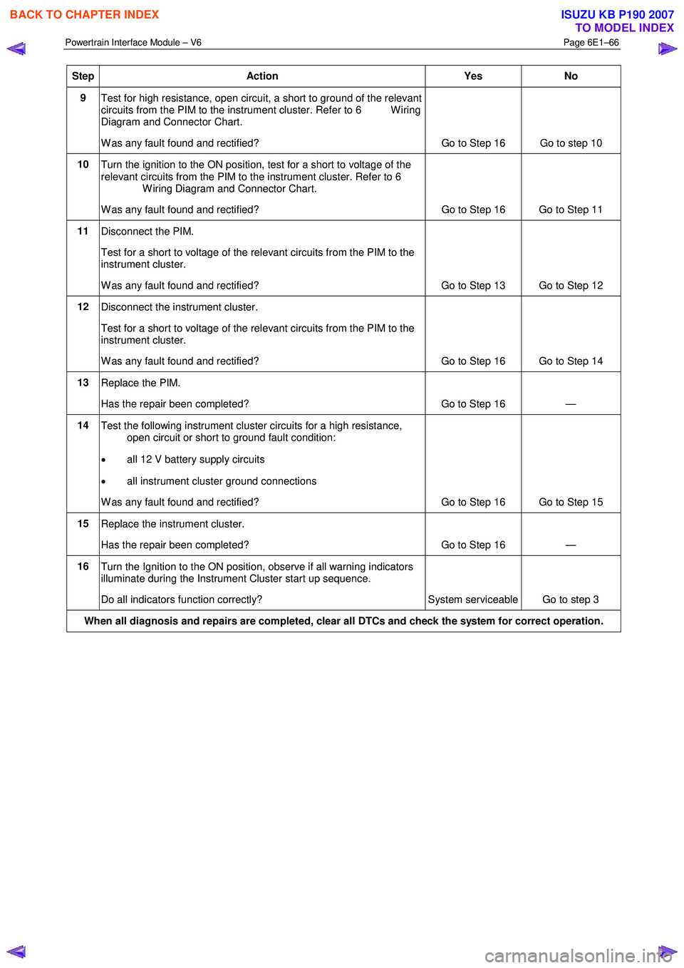
Step Action Yes No
9
Test for high resistance, open circuit, a short to ground of the relevant
circuits from the PIM to the instrument cluster. Refer to 6 W iring
Diagram and Connector Chart.
W as any fault found and rectified? Go to Step 16 Go to step 10
10
Turn the ignition to the ON position, test for a short to voltage of the
relevant circuits from the PIM to the instrument cluster. Refer to 6
W iring Diagram and Connector Chart.
W as any fault found and rectified? Go to Step 16 Go to Step 11
11
Disconnect the PIM.
Test for a short to voltage of the relevant circuits from the PIM to the
instrument cluster.
W as any fault found and rectified? Go to Step 13 Go to Step 12
12 Disconnect the instrument cluster.
Test for a short to voltage of the relevant circuits from the PIM to the
instrument cluster.
W as any fault found and rectified? Go to Step 16 Go to Step 14
13 Replace the PIM.
Has the repair been completed? Go to Step 16 —
14 Test the following instrument cluster circuits for a high resistance,
open circuit or short to ground fault condition:
• all 12 V battery supply circuits
• all instrument cluster ground connections
W as any fault found and rectified? Go to Step 16 Go to Step 15
15 Replace the instrument cluster.
Has the repair been completed? Go to Step 16 —
16 Turn the Ignition to the ON position, observe if all warning indicators
illuminate during the Instrument Cluster start up sequence.
Do all indicators function correctly? System serviceable Go to step 3
When all diagnosis and repairs are completed, clear all DTCs and check the system for correct operation.
BACK TO CHAPTER INDEX
TO MODEL INDEX
ISUZU KB P190 2007
Page 3728 of 6020
Powertrain Interface Module – V6 Page 6E1–67
10.3 Tachometer Diagnostics
Circuit Description
The powertrain interface module (PIM) receives the tachomer signal from the engine control module (ECM), it is then
sent to the instrument cluster by the PIM via a hard wired connection to drive the tachometer which displays the engine
RPM. Some of these components do not set a DTC, in the event of a component failure. The following diagnostic
procedures are devised to assist in these cases.
Additional Information
• Refer to 7.2 Diagnostic System Check to monitor DTC’s.
• Refer to 8A Electrical Body and Chassis for the following information:
• ECM wiring diagram.
• Refer to 6 W iring Diagram and Connector Chart for the following information:
• PIM connector illustration and terminal assignment, and
• PIM wiring diagram.
• For intermittent faults, refer to Intermittent Fault Conditions.
• Check for an intermittent fault in the wiring harness or connectors, if a fault cannot be found the system is
serviceable.
Since fault conditions in a wiring connector may trigger DTCs, always test the connectors related to this diagnostic
procedure for shorted terminals or poor wiring connection before replacing any component. Refer to 8A Electrical - Body
and Chassis for information on electrical fault diagnosis.
Test Description
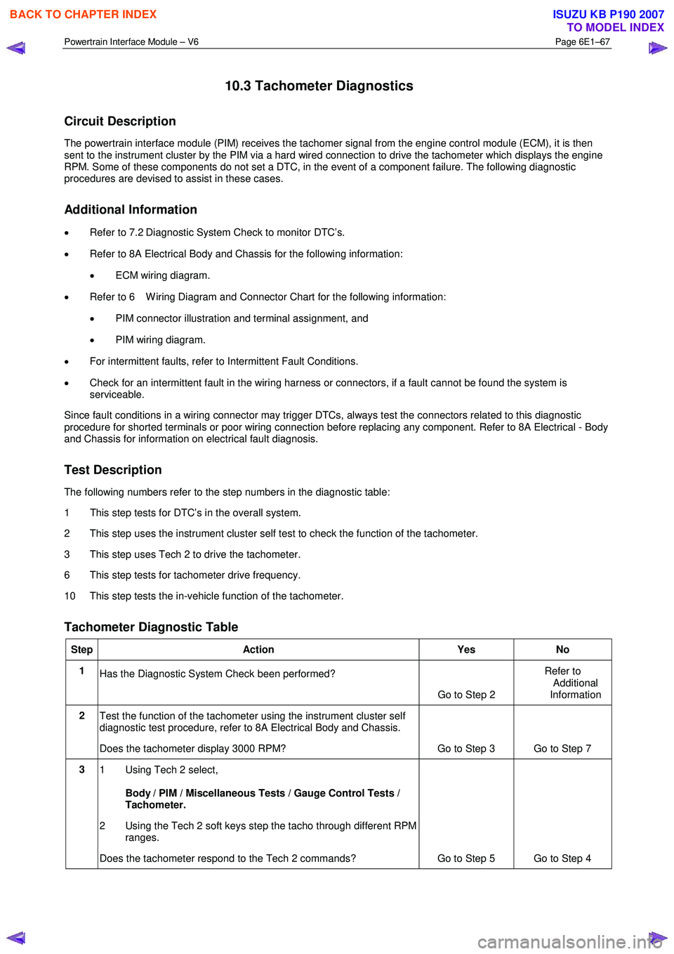
The following numbers refer to the step numbers in the diagnostic table:
1 This step tests for DTC’s in the overall system.
2 This step uses the instrument cluster self test to check the function of the tachometer.
3 This step uses Tech 2 to drive the tachometer.
6 This step tests for tachometer drive frequency.
10 This step tests the in-vehicle function of the tachometer.
Tachometer Diagnostic Table
Step Action Yes No
1
Has the Diagnostic System Check been performed?
Go to Step 2 Refer to
Additional
Information
2 Test the function of the tachometer using the instrument cluster self
diagnostic test procedure, refer to 8A Electrical Body and Chassis.
Does the tachometer display 3000 RPM? Go to Step 3 Go to Step 7
3 1 Using Tech 2 select,
Body / PIM / Miscellaneous Tests / Gauge Control Tests /
Tachometer.
2 Using the Tech 2 soft keys step the tacho through different RPM ranges.
Does the tachometer respond to the Tech 2 commands? Go to Step 5 Go to Step 4
BACK TO CHAPTER INDEX
TO MODEL INDEX
ISUZU KB P190 2007
Page 3729 of 6020

Powertrain Interface Module – V6 Page 6E1–68
4
Test for high resistance, open circuit, a short to ground of the relevant
circuits from the PIM to the instrument cluster. Refer to 6 W iring
Diagram and Connector Chart.
W as any fault found and rectified? Go to Step 10 Go to Step 5
5
Turn the ignition to the ON position, test for a short to voltage of the
relevant circuits from the PIM to the instrument cluster. Refer to 6
W iring Diagram and Connector Chart.
W as any fault found and rectified? Go to Step 10 Go to Step 6
6
Measure the frequency at the tachometer signal output from the ECM,
refer to 8A Electrical Body and Chassis.
Is the tachometer frequency present? Go to Step 7 Refer to
6C1-2 Engine Management
Diagnostics
7 Replace the PIM.
Has the repair been completed? Go to Step 10 —
8 Test the following instrument cluster circuits for a high resistance,
open circuit or short to ground fault condition:
• all 12 V battery supply circuits
• all instrument cluster ground connections
W as any fault found and rectified? Go to Step 10 Go to Step 9
9 Replace the instrument cluster.
Has the repair been completed? Go to Step 10 —
10 Start the vehicles engine.
Does the tachometer function normally? System OK Go to Step 2
When all diagnosis and repairs are completed, clear all DTCs and check the system for correct operation.
BACK TO CHAPTER INDEX
TO MODEL INDEX
ISUZU KB P190 2007
Page 3730 of 6020
Powertrain Interface Module – V6 Page 6E1–69
10.4 Temperature Gauge Diagnostics
Circuit Description
The powertrain interface module (PIM) receives engine temperature status via the GM Lan serial data bus from the
engine control module (ECM) it is then sent to the instrument cluster by the PIM via a hard wired connection to drive the
temperature gauge to the appropriate position. Some of these components do not set a DTC, in the event of a
component failure. The following diagnostic procedures are devised to assist in these cases.
Additional Information
• Refer to 7.2 Diagnostic System Check to monitor DTC’s.
• Refer to 8A Electrical Body and Chassis for the following information:
• ECM wiring diagram.
• Refer to 6 W iring Diagram and Connector Chart for the following information:
• PIM connector illustration and terminal assignment, and
• PIM wiring diagram.
• For intermittent faults, refer to Intermittent Fault Conditions.
• Check for an intermittent fault in the wiring harness or connectors, if a fault cannot be found the system is
serviceable.
Since fault conditions in a wiring connector may trigger DTCs, always test the connectors related to this diagnostic
procedure for shorted terminals or poor wiring connection before replacing any component. Refer to 8A Electrical - Body
and Chassis for information on electrical fault diagnosis.
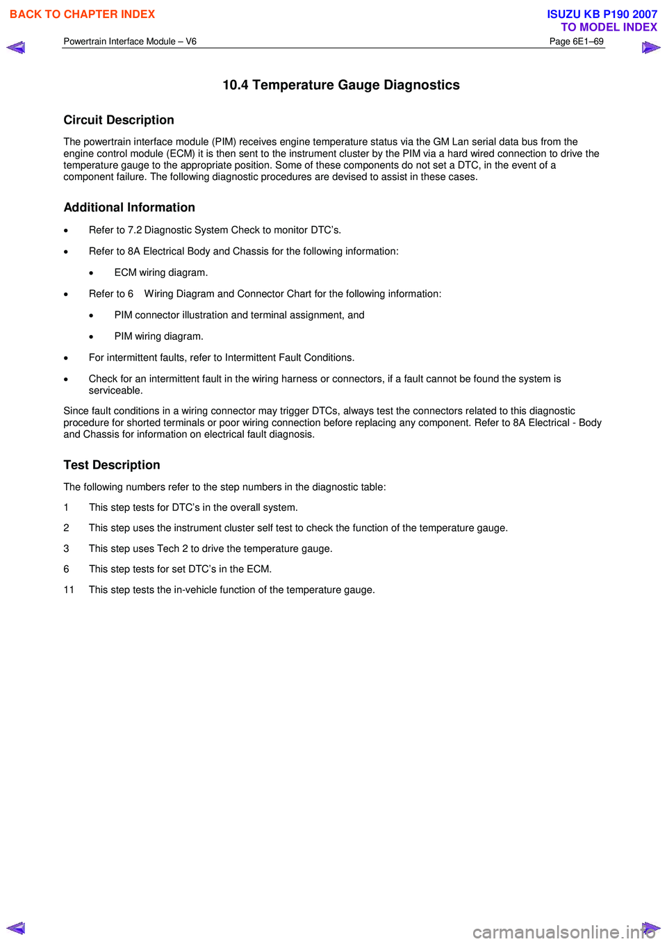
Test Description
The following numbers refer to the step numbers in the diagnostic table:
1 This step tests for DTC’s in the overall system.
2 This step uses the instrument cluster self test to check the function of the temperature gauge.
3 This step uses Tech 2 to drive the temperature gauge.
6 This step tests for set DTC’s in the ECM.
11 This step tests the in-vehicle function of the temperature gauge.
BACK TO CHAPTER INDEX
TO MODEL INDEX
ISUZU KB P190 2007
Page 3731 of 6020
Powertrain Interface Module – V6 Page 6E1–70
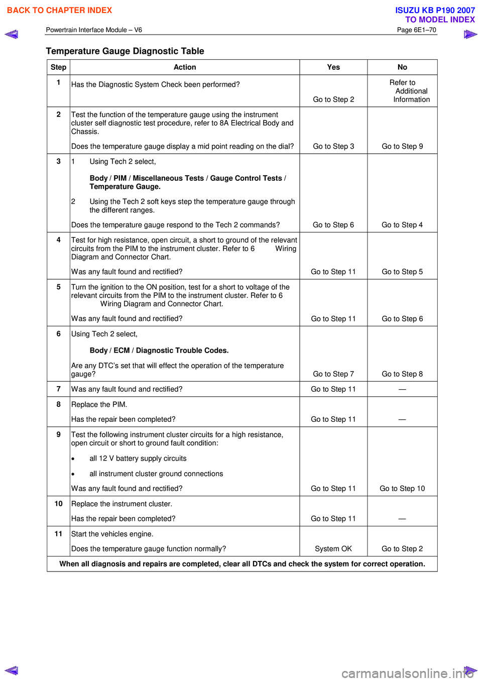
Temperature Gauge Diagnostic Table
Step Action Yes No
1
Has the Diagnostic System Check been performed?
Go to Step 2 Refer to
Additional
Information
2 Test the function of the temperature gauge using the instrument
cluster self diagnostic test procedure, refer to 8A Electrical Body and
Chassis.
Does the temperature gauge display a mid point reading on the dial? Go to Step 3 Go to Step 9
3
1 Using Tech 2 select,
Body / PIM / Miscellaneous Tests / Gauge Control Tests /
Temperature Gauge.
2 Using the Tech 2 soft keys step the temperature gauge through the different ranges.
Does the temperature gauge respond to the Tech 2 commands? Go to Step 6 Go to Step 4
4 Test for high resistance, open circuit, a short to ground of the relevant
circuits from the PIM to the instrument cluster. Refer to 6 W iring
Diagram and Connector Chart.
W as any fault found and rectified? Go to Step 11 Go to Step 5
5 Turn the ignition to the ON position, test for a short to voltage of the
relevant circuits from the PIM to the instrument cluster. Refer to 6
W iring Diagram and Connector Chart.
W as any fault found and rectified? Go to Step 11 Go to Step 6
6
Using Tech 2 select,
Body / ECM / Diagnostic Trouble Codes.
Are any DTC’s set that will effect the operation of the temperature
gauge? Go to Step 7 Go to Step 8
7 W as any fault found and rectified? Go to Step 11 —
8 Replace the PIM.
Has the repair been completed? Go to Step 11 —
9 Test the following instrument cluster circuits for a high resistance,
open circuit or short to ground fault condition:
• all 12 V battery supply circuits
• all instrument cluster ground connections
W as any fault found and rectified? Go to Step 11 Go to Step 10
10 Replace the instrument cluster.
Has the repair been completed? Go to Step 11 —
11 Start the vehicles engine.
Does the temperature gauge function normally? System OK Go to Step 2
When all diagnosis and repairs are completed, clear all DTCs and check the system for correct operation.
BACK TO CHAPTER INDEX
TO MODEL INDEX
ISUZU KB P190 2007
Page 3761 of 6020
Automatic Transmission – 4L60E – General Information Page 7C1–1
7C1
Automatic Transmission – 4L60E –
General Information
ATTENTION
Before performing any service operation or other procedure described in this Section, refer to Warnings, Cautions and Notes for correct workshop practices with regard to safety and/or property damage.
1 Section Descriptions ........................................................................................................... ...................3
1.1 WARNINGS, CAUTIONS and NOTES................................................................................................... ................. 3
Definition of WARNING, CAUTION and NOTE Statements ............................................................................. .... 3
WARNING Defined............................................................................................................................................. 3
CAUTION Defined .............................................................................................................................................. 3
NOTE Defined .................................................................................................................................................... 3
1.2 7C1 Automatic Transmission – 4L60E – General Information ....................................................................... .... 4
Recommendations ................................................................................................................................................. 4
Oil Cooler Pipes ..................................................................................................................................................... 4
Clean and Inspect .............................................................................................................. .................................... 5
1.3 7C2 Automatic Transmission – 4L60E – Electrical Diagnosis ...................................................................... ..... 5
1.4 7C3 Automatic Transmission – 4L60E – Hydraulic and Mechanical Diagnosis ............................................... 5
1.5 7C4 Automatic Transmission – 4L60E – On-vehicle Servicing ...................................................................... .... 5
2 General information ...............................................................................................................................6
2.1 Transmission Control Module – HFV6 ............................................................................................. .................... 6
2.2 Transmission Identification .................................................................................................................................. 6
2.3 Economy, Power and Cruise Modes .................................................................................................................... 7
Economy Mode ...................................................................................................................................................... 7
Power Mode ............................................................................................................................................................ 7
Cruise Mode ........................................................................................................................................................... 7
2.4 System Protection Devices ...................................................................................................... ............................. 8
2.5 Self Diagnosis ........................................................................................................................................................ 8
2.6 TCM Sensors and Actuators ................................................................................................................................. 8
3 Transmission Control Module Operation Overview ...........................................................................9
3.1 Transmission Control Module .............................................................................................................................. 9
Component Location ............................................................................................................. ................................ 9
Transmission Control Module Data Transfer ...................................................................................... ................ 9
Transmission Control Module Operation........................................................................................................... 10
3.2 TCM Wiring Diagrams.......................................................................................................................................... 10
4 Transmission Definitions and Abbreviations ....................................................................................1 1
4.1 Throttle Position Related Definitions ................................................................................................................. 11
4.2 Noise Condition Related Definitions ............................................................................................ ...................... 11
4.3 General Definitions .............................................................................................................................................. 11
4.4 Abbreviations ....................................................................................................................................................... 14
5 Service Notes ........................................................................................................................................15
Fasteners .............................................................................................................................................................. 15
General Workshop Practice ................................................................................................................................ 15
6 Torque Specifications .......................................................................................................... ................16
7 Transmission Specifications.................................................................................................... ...........17
BACK TO CHAPTER INDEX
TO MODEL INDEX
ISUZU KB P190 2007
Page 3769 of 6020
Automatic Transmission – 4L60E – General Information Page 7C1–9
3 Transmission Control Module
Operation Overview
3.1 Transmission Control Module
W ith the introduction of the new HFV6 engine, the powertrain architecture has been redesigned to accommodate this
introduction. W ith this design, a new bus architecture and protocol has also been introduced. The new bus connects the
following modules:
• engine control module (ECM),
• transmission control module (TCM),
• powertrain interface module (PIM) and
• ABS module.
The protocol used to communicate between these modules is called General Motors Local Area Network (GM LAN)
which is based on Controller Area Network (CAN) communication protocol. For further information on GM LAN protocol
and data bus structure, refer to 6E1 Powertrain Interface Module – V6.
Component Location
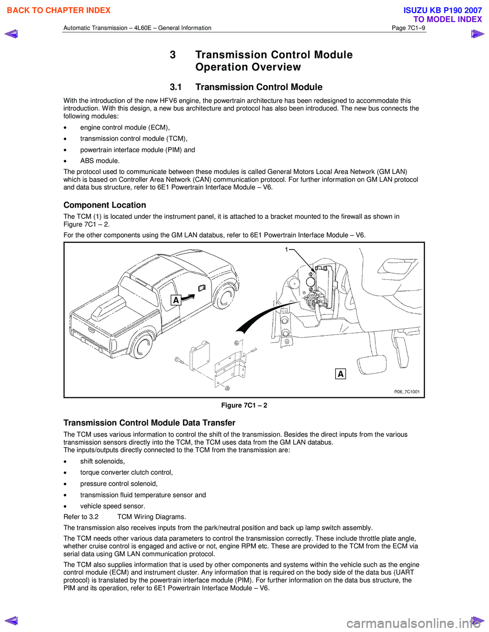
The TCM (1) is located under the instrument panel, it is attached to a bracket mounted to the firewall as shown in
Figure 7C1 – 2.
For the other components using the GM LAN databus, refer to 6E1 Powertrain Interface Module – V6.
Figure 7C1 – 2
Transmission Control Module Data Transfer
The TCM uses various information to control the shift of the transmission. Besides the direct inputs from the various
transmission sensors directly into the TCM, the TCM uses data from the GM LAN databus.
The inputs/outputs directly connected to the TCM from the transmission are:
• shift solenoids,
• torque converter clutch control,
• pressure control solenoid,
• transmission fluid temperature sensor and
• vehicle speed sensor.
Refer to 3.2 TCM Wiring Diagrams.
The transmission also receives inputs from the park/neutral position and back up lamp switch assembly.
The TCM needs other various data parameters to control the transmission correctly. These include throttle plate angle,
whether cruise control is engaged and active or not, engine RPM etc. These are provided to the TCM from the ECM via
serial data using GM LAN communication protocol.
The TCM also supplies information that is used by other components and systems within the vehicle such as the engine
control module (ECM) and instrument cluster. Any information that is required on the body side of the data bus (UART
protocol) is translated by the powertrain interface module (PIM). For further information on the data bus structure, the
PIM and its operation, refer to 6E1 Powertrain Interface Module – V6.
BACK TO CHAPTER INDEX
TO MODEL INDEX
ISUZU KB P190 2007
Page 3770 of 6020
Automatic Transmission – 4L60E – General Information Page 7C1–10
Transmission Control Module Operation
The TCM processes data every 10 milliseconds from various sensors, such as throttle position, vehicle speed, gear
range, temperature, engine load and other inputs. The TCM compares all its various inputs with the internal programming
and calibration of the TCM using this data, a signal is transmitted to the valve body shift solenoids, which activate the
shift valves for precise shift control. Shift points are therefore precisely controlled and are identical from vehicle to vehic le.
The TCM also control torque converter clutch apply and release.
Shift feel is also electronically controlled by the TCM, by signals sent to the variable force solenoid, which controls fluid
line pressure and it is this pressure that precisely determines how the shifts will feel. In this way, the TCM electronically
synchronises the engine and transmission into a single integrated powertrain system for optimum performance, shift
timing, fuel efficiency and emission control.
3.2 TCM Wiring Diagrams
For details of the transmission control module (TCM) wiring diagrams, refer to 8A Electrical-Body and Chassis.
BACK TO CHAPTER INDEX
TO MODEL INDEX
ISUZU KB P190 2007