Page 3971 of 6020
TRANSMISSION CONTROL SYSTEM (AW30–40LE) 7A2-5
Electronic Control Diagram
RTW 77AXF000201
BACK TO CHAPTER INDEX
TO MODEL INDEX
ISUZU KB P190 2007
Page 3977 of 6020
TRANSMISSION CONTROL SYSTEM (AW30–40LE) 7A2-11
Control System Diagram
RTW 77AXF000301
BACK TO CHAPTER INDEX
TO MODEL INDEX
ISUZU KB P190 2007
Page 3982 of 6020

7A2-16 TRANSMISSION CONTROL SYSTEM (AW30–40LE)
CAN bus systems in automatic
transmission control (AW30-40LE)
The automatic transmission control system in AW 30-
40LE uses high speed CAN bus system .The individual
CAN bus systems are connected via two interfaces and
can exchange information and data. This allows control
modules that are connected to different CAN bus
systems to communicate.
High speed CAN bus
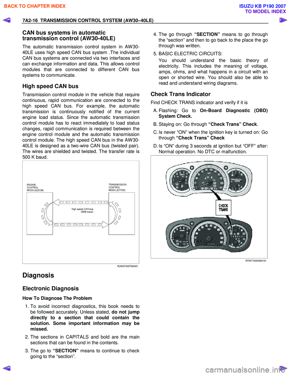
Transmission control module in the vehicle that require
continuous, rapid communication are connected to the
high speed CAN bus. For example, the automatic
transmission is continuously notified of the current
engine load status. Since the automatic transmission
control module has to react immediately to load status
changes, rapid communication is required between the
engine control module and the automatic transmission
control module. The high speed CAN bus in the AW 30-
40LE is designed as a two-wire CAN bus (twisted pair).
The wires are shielded and twisted. The transfer rate is
500 K baud.
RUW 37ASF000401
Diagnosis
Electronic Diagnosis
How To Diagnose The Problem
1. To avoid incorrect diagnostics, this book needs to
be followed accurately. Unless stated, do not jump
directly to a section that could contain the
solution. Some important information may be
missed.
2. The sections in CAPITALS and bold are the main
sections that can be found in the contents.
3. The go to “SECTION” means to continue to check
going to the “section”.
4. The go through “SECTION” means to go through
the “section” and then to go back to the place the go
through was written.
5. BASIC ELECTRIC CIRCUITS:
You should understand the basic theory o
f
electricity. This includes the meaning of voltage,
amps, ohms, and what happens in a circuit with an
open or shorted wire. You should also be able to
read and understand wiring diagrams.
Check Trans Indicator
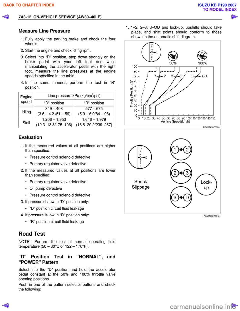
Find CHECK TRANS indicator and verify if it is
A. Flashing: Go to On-Board Diagnostic (OBD)
System Check.
B. Staying on: Go through “Check Trans” Check.
C. Is never “ON” when the ignition key is turned on: Go through “Check Trans” Check
D. Is “ON” during 3 seconds at ignition but “OFF” after: Normal operation. No DTC or malfunction.
RTW 77ASH000101
BACK TO CHAPTER INDEX
TO MODEL INDEX
ISUZU KB P190 2007
Page 4097 of 6020

7A3-12 ON-VEHICLE SERVICE (AW30–40LE)
Measure Line Pressure
1. Fully apply the parking brake and chock the four
wheels.
2. Start the engine and check idling rpm.
3. Select into “D" position, step down strongly on the brake pedal with your left foot and while
manipulating the accelerator pedal with the right
foot, measure the line pressures at the engine
speeds specified in the table.
4. In the same manner, perform the test in “R" position.
Line pressure kPa (kg/cm
2/psi) Engine
speed “D" position “R" position
Idling 349 – 408
(3.6 – 4.2 /51 – 59) 577 – 675
(5.9 – 6.9/84 – 98)
Stall 1,206 – 1,353
(12.3–13.8/175–196) 1,646 – 1,979
(16.8–20.2/239–287)
Evaluation
1. If the measured values at all positions are higher
than specified:
• Pressure control solenoid defective
• Primary regulator valve defective
2. If the measured values at all positions are lowe
r
than specified:
• Primary regulator valve defective
• Oil pump defective
• Pressure control solenoid defective
3. If pressure is low in “D" position only:
• “D" position circuit fluid leakage
4. If pressure is low in “R" position only:
• “R" position circuit fluid leakage
Road Test
NOTE: Perform the test at normal operating fluid
temperature (50 – 80 °C or 122 – 176 °F).
“D" Position Test in “NORMAL", and
“POWER" Pattern
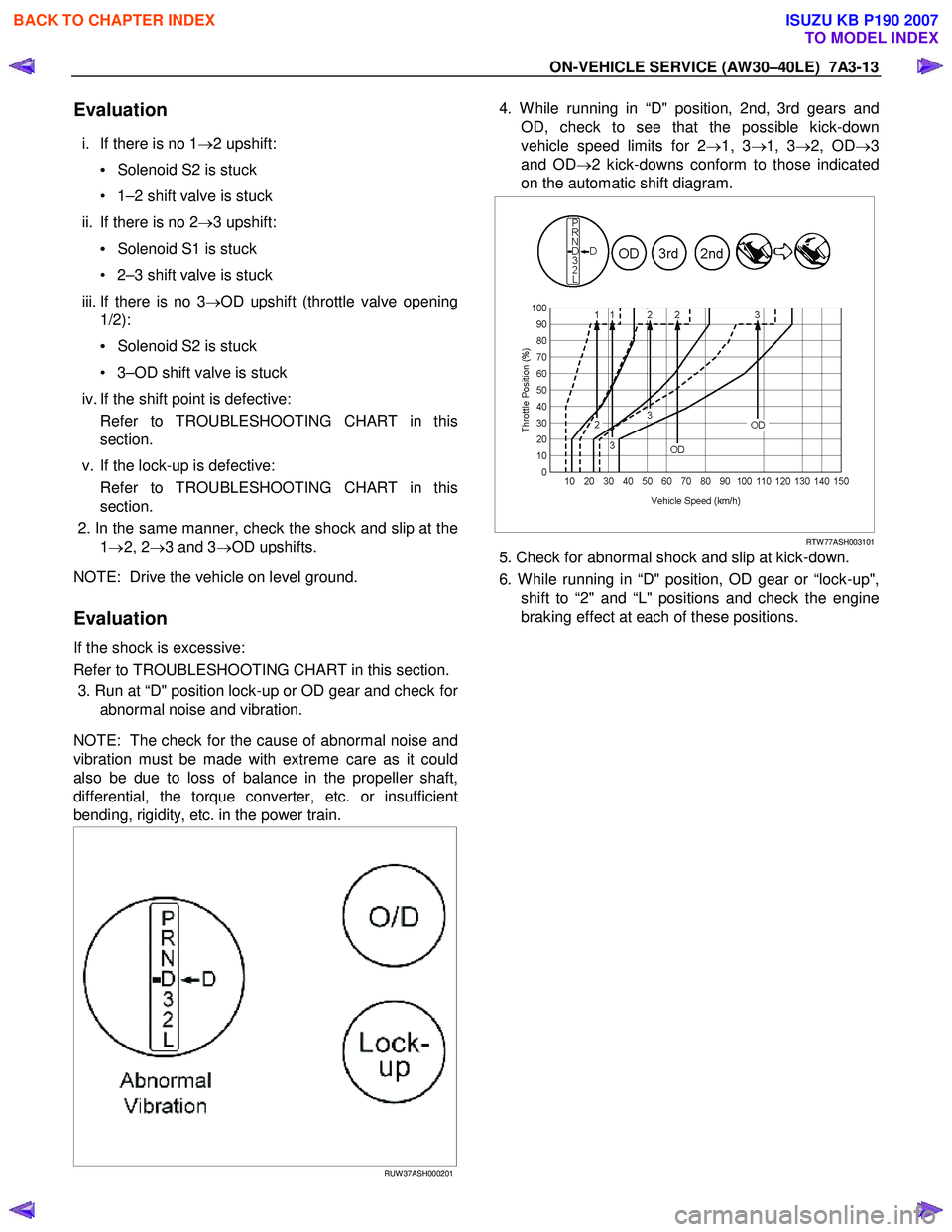
Select into the “D" position and hold the accelerator
pedal constant at the 50% and 100% throttle valve
opening positions.
Push in one of the pattern selector buttons and check
the following:
1. 1–2, 2–3, 3–OD and lock-up, upshifts should take
place, and shift points should conform to those
shown in the automatic shift diagram.
RTW 77ASH003001
RUA37ASH000101
BACK TO CHAPTER INDEX
TO MODEL INDEX
ISUZU KB P190 2007
Page 4098 of 6020

ON-VEHICLE SERVICE (AW30–40LE) 7A3-13
Evaluation
i. If there is no 1→2 upshift:
• Solenoid S2 is stuck
• 1–2 shift valve is stuck
ii. If there is no 2 →3 upshift:
• Solenoid S1 is stuck
• 2–3 shift valve is stuck
iii. If there is no 3 →OD upshift (throttle valve opening
1/2):
• Solenoid S2 is stuck
• 3–OD shift valve is stuck
iv. If the shift point is defective: Refer to TROUBLESHOOTING CHART in this
section.
v. If the lock-up is defective: Refer to TROUBLESHOOTING CHART in this
section.
2. In the same manner, check the shock and slip at the 1→ 2, 2 →3 and 3 →OD upshifts.
NOTE: Drive the vehicle on level ground.
Evaluation
If the shock is excessive:
Refer to TROUBLESHOOTING CHART in this section. 3. Run at “D" position lock-up or OD gear and check fo
r
abnormal noise and vibration.
NOTE: The check for the cause of abnormal noise and
vibration must be made with extreme care as it could
also be due to loss of balance in the propeller shaft,
differential, the torque converter, etc. or insufficient
bending, rigidity, etc. in the power train.
RUW 37ASH000201
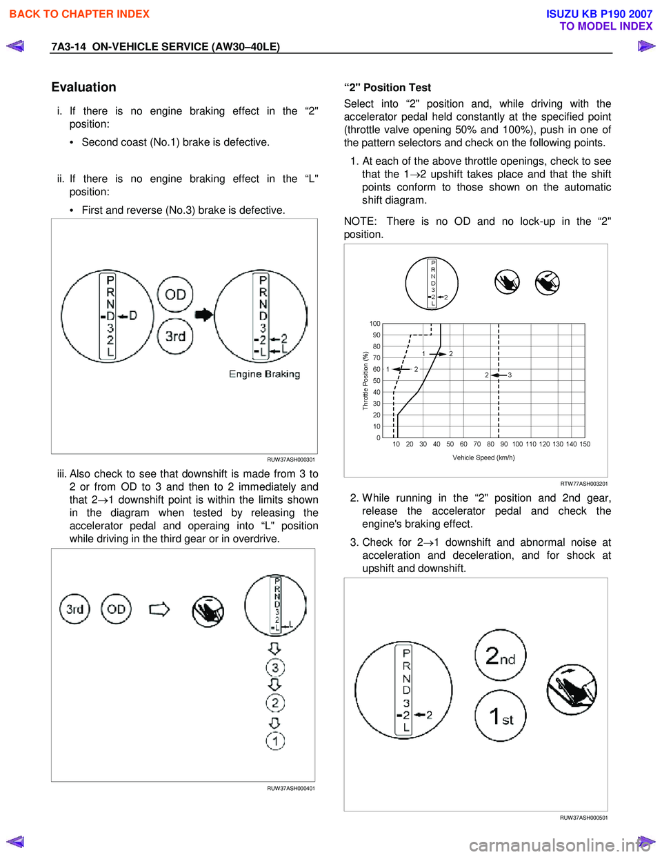
4. W hile running in “D" position, 2nd, 3rd gears and
OD, check to see that the possible kick-down
vehicle speed limits for 2 →1, 3 →1, 3 →2, OD →3
and OD →2 kick-downs conform to those indicated
on the automatic shift diagram.
RTW 77ASH003101
5. Check for abnormal shock and slip at kick-down.
6. W hile running in “D" position, OD gear or “lock-up", shift to “2" and “L" positions and check the engine
braking effect at each of these positions.
BACK TO CHAPTER INDEX
TO MODEL INDEX
ISUZU KB P190 2007
Page 4099 of 6020

7A3-14 ON-VEHICLE SERVICE (AW30–40LE)
Evaluation
i. If there is no engine braking effect in the “2"
position:
• Second coast (No.1) brake is defective.
ii. If there is no engine braking effect in the “L" position:
• First and reverse (No.3) brake is defective.
RUW 37ASH000301
iii. Also check to see that downshift is made from 3 to
2 or from OD to 3 and then to 2 immediately and
that 2 →1 downshift point is within the limits shown
in the diagram when tested by releasing the
accelerator pedal and operaing into “L" position
while driving in the third gear or in overdrive.
RUW 37ASH000401
“2" Position Test
Select into “2" position and, while driving with the
accelerator pedal held constantly at the specified point
(throttle valve opening 50% and 100%), push in one o
f
the pattern selectors and check on the following points.
1.
At each of the above throttle openings, check to see
that the 1 →2 upshift takes place and that the shift
points conform to those shown on the automatic
shift diagram.
NOTE: There is no OD and no lock-up in the “2"
position.
RTW 77ASH003201
2. W hile running in the “2" position and 2nd gear,
release the accelerator pedal and check the
engine's braking effect.
3. Check for 2 →1 downshift and abnormal noise at
acceleration and deceleration, and for shock at
upshift and downshift.
RUW 37ASH000501
BACK TO CHAPTER INDEX
TO MODEL INDEX
ISUZU KB P190 2007
Page 4100 of 6020
ON-VEHICLE SERVICE (AW30–40LE) 7A3-15
“L" Position Test
1. W hile running above 80 km/h (50 mph) in the “D"
position, release your foot from the accelerato
r
pedal and shift into the “L" position.
Then check to see that the 2 →1 downshift occurs at
the specified point shown on the automatic shift
diagram.
RUW 37ASH000601
2. W hile running in the “L" position, check to see that
there is no upshift to 2nd gear.
3. W hile running in the “L" position, release the accelerator pedal and check the engine braking
effect.
4. Check for abnormal noise during acceleration and deceleration.
RUW 37ASH000701
“R" Position Test
Select into the “R" position and, while starting at full
throttle, check for slipping.
RUW 37ASH000801
“P" Position Test
Stop the vehicle on a grade (more than 9%) and afte
r
shifting into the “P" position, release the parking brake.
Then check to see that the parking lock pawl holds the
vehicle in place.
BACK TO CHAPTER INDEX
TO MODEL INDEX
ISUZU KB P190 2007
Page 4241 of 6020
7A1-2 CONSTRUCTION AND FUNCTION
PAGE
Learning Function ......................................................................................................7A1- 33
Major Input/Output Component and Their Functions .............................................7A1- 34
Control Circuit Block Diagram ..................................................................................7A1- 35
Gear Train (Transmission Mechanism) Operation and Hydraulic Circuit ..................7A1- 36
Construction and Operation .....................................................................................7A1- 36
Component Name and Function ...............................................................................7A1- 36
Component and Their Operating Condition ............................................................7A1- 37
BACK TO CHAPTER INDEX
TO MODEL INDEX
ISUZU KB P190 2007