2007 ISUZU KB P190 Circuit
[x] Cancel search: CircuitPage 5602 of 6020
Cruise Control – HFV6 Page 8C–24
3.4 Clutch Pedal Switch (Manual Only)
Remove
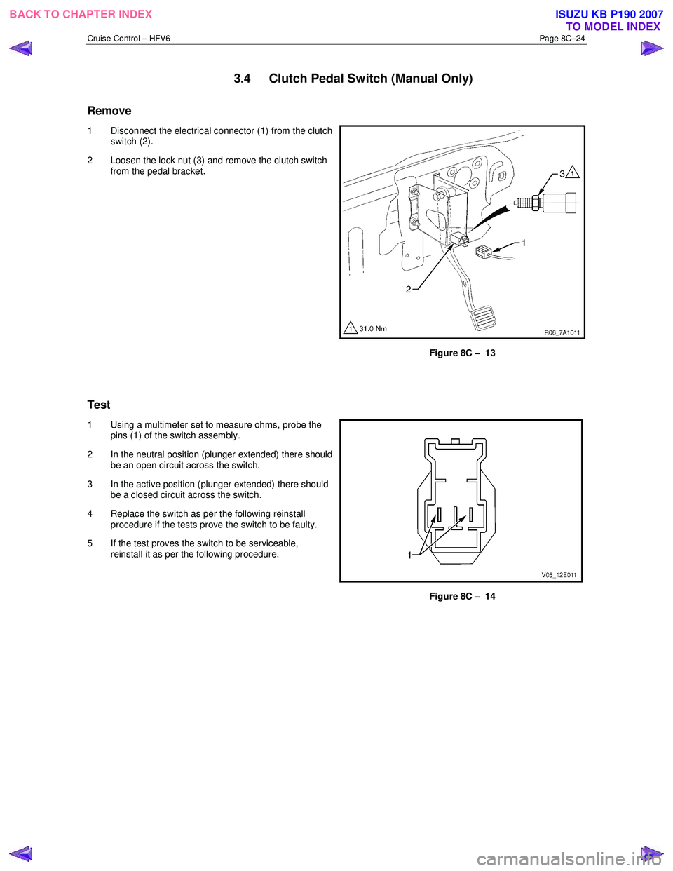
1 Disconnect the electrical connector (1) from the clutch
switch (2).
2 Loosen the lock nut (3) and remove the clutch switch from the pedal bracket.
Figure 8C – 13
Test
1 Using a multimeter set to measure ohms, probe the pins (1) of the switch assembly.
2 In the neutral position (plunger extended) there should be an open circuit across the switch.
3 In the active position (plunger extended) there should be a closed circuit across the switch.
4 Replace the switch as per the following reinstall procedure if the tests prove the switch to be faulty.
5 If the test proves the switch to be serviceable, reinstall it as per the following procedure.
Figure 8C – 14
BACK TO CHAPTER INDEX TO MODEL INDEXISUZU KB P190 2007
Page 5606 of 6020
ACCESSORIES 9-1
SECTION 9
ACCESSORIES
TABLE OF CONTENTS
PAGE
Parts Location ................................................................................................................ ... 9 −
−−
−
2
Circuit Diagram ............................................................................................................... ... 9 −
−−
−
6
Connector List ................................................................................................................ ... 9 −
−−
−
22
Audio ......................................................................................................................... ......... 9 −
−−
−
24
Front Speaker ................................................................................................................. ... 9 −
−−
−
25
Tweeter ........................................................................................................................ ........ 9 −
−−
−
26
Rear Speaker (Extend Cab) .............................................................................................. 9 −
−−
−
27
Rear Speaker (Crew Cab) ................................................................................................. 9 −
−−
−
28
Clock.......................................................................................................................... .......... 9 −
−−
−
29
Antenna ....................................................................................................................... ....... 9 −
−−
−
30
BACK TO CHAPTER INDEX
TO MODEL INDEXISUZU KB P190 2007
Page 5611 of 6020
9-6 ACCESSORIES
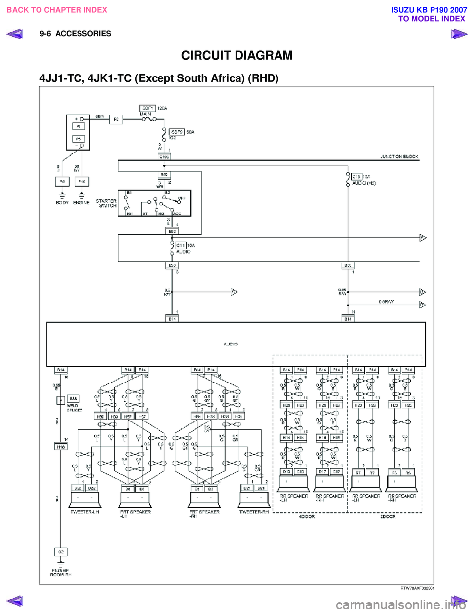
CIRCUIT DIAGRAM
4JJ1-TC, 4JK1-TC (Except South Africa) (RHD)
RTW 78AXF032301
BACK TO CHAPTER INDEX
TO MODEL INDEXISUZU KB P190 2007
Page 5636 of 6020
SUPPLEMENTAL RESTRAINT SYSTEM 9A-1
SECTION 9A
SUPPLEMENTAL RESTRAINT SYSTEM (SRS)
TABLE OF CONTENTS
PAGE
Service Precaution ....................................................................................................... 9A- 4
General Description...................................................................................................... 9A- 4 Restraint Devices ..................................................................................................... 9A- 4
System Description .................................................................................................. 9A- 5
Circuit Diagram ............................................................................................................. 9A- 6
SRS Component And Wiring Location View .............................................................. 9A- 10
Component Description ............................................................................................... 9A- 14 SRS Control Unit ...................................................................................................... 9A- 14
"SRS" Warning Lamp .............................................................................................. 9A- 14
SRS Coil Assembly .................................................................................................. 9A- 15
Air Bag Assemblies.................................................................................................. 9A- 15
Steering Column ...................................................................................................... 9A- 16
Knee Bolster ............................................................................................................. 9A- 16
Definitions .................................................................................................................... . 9A- 16
Diagnosis...................................................................................................................... . 9A- 18
Diagnostic Trouble Codes ....................................................................................... 9A- 18
Scan Tool Diagnostics............................................................................................. 9A- 18
Use Of Special Tools ............................................................................................... 9A- 18
SRS Connec tor Body Face Vie ws ............................................................................. ..9 A- 19
Repairs And Inspec tions Required After A n A ccident ............................................ ..9 A- 20
Accident With Deployment-Component Replacement And Inspections ............. 9A- 20
Accident With or Without Deployment-Component Inspection ........................... 9A- 20
SRS Control Unit Replacement Guidelines ........................................................... 9A- 20
Wiring Damage ......................................................................................................... 9A- 20
SRS Connector (Plastic Body And Terminal Metal Pin) Damage ......................... 9A- 20
SRS Wire Pigtail Damage ........................................................................................ 9A- 20
PAGE 1 OF 3
BACK TO CHAPTER INDEX TO MODEL INDEXISUZU KB P190 2007
Page 5641 of 6020
9A-6 SUPPLEMENTAL RESTRAINT SYSTEM
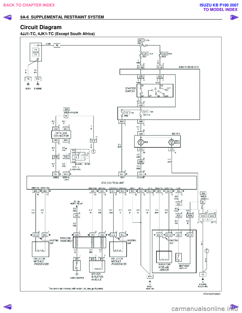
Circuit Diagram
4JJ1-TC, 4JK1-TC (Except South Africa)
RTW 78AXF028601
BACK TO CHAPTER INDEX
TO MODEL INDEXISUZU KB P190 2007
Page 5650 of 6020
SUPPLEMENTAL RESTRAINT SYSTEM 9A-15
RTW 79ASH000501
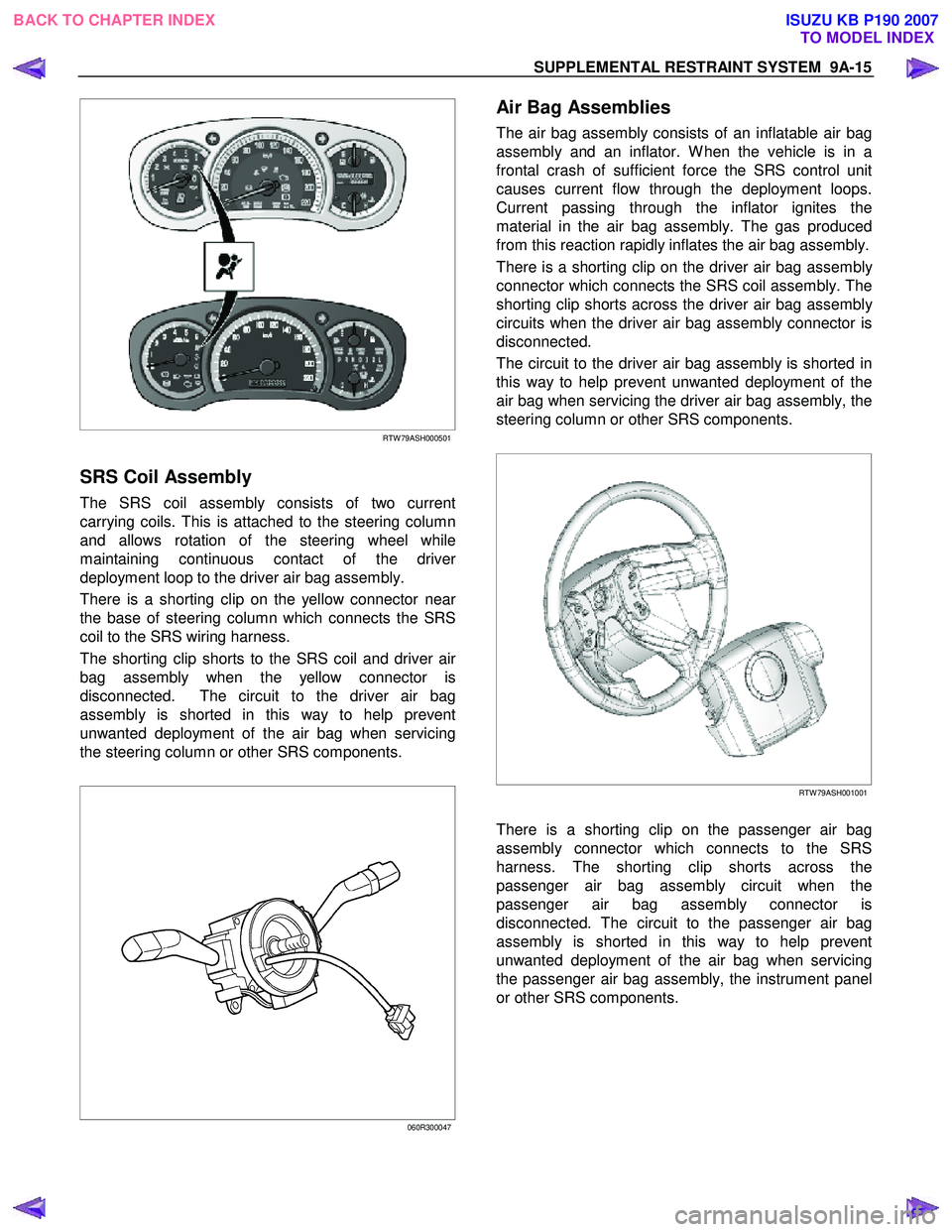
SRS Coil Assembly
The SRS coil assembly consists of two current
carrying coils. This is attached to the steering column
and allows rotation of the steering wheel while
maintaining continuous contact of the drive
r
deployment loop to the driver air bag assembly.
There is a shorting clip on the yellow connector nea
r
the base of steering column which connects the SRS
coil to the SRS wiring harness.
The shorting clip shorts to the SRS coil and driver ai
r
bag assembly when the yellow connector is
disconnected. The circuit to the driver air bag
assembly is shorted in this way to help prevent
unwanted deployment of the air bag when servicing
the steering column or other SRS components.
060R300047
Air Bag Assemblies
The air bag assembly consists of an inflatable air bag
assembly and an inflator. W hen the vehicle is in a
frontal crash of sufficient force the SRS control unit
causes current flow through the deployment loops.
Current passing through the inflator ignites the
material in the air bag assembly. The gas produced
from this reaction rapidly inflates the air bag assembly.
There is a shorting clip on the driver air bag assembl
y
connector which connects the SRS coil assembly. The
shorting clip shorts across the driver air bag assembl
y
circuits when the driver air bag assembly connector is
disconnected.
The circuit to the driver air bag assembly is shorted in
this way to help prevent unwanted deployment of the
air bag when servicing the driver air bag assembly, the
steering column or other SRS components.
RTW 79ASH001001
There is a shorting clip on the passenger air bag
assembly connector which connects to the SRS
harness. The shorting clip shorts across the
passenger air bag assembly circuit when the
passenger air bag assembly connector is
disconnected. The circuit to the passenger air bag
assembly is shorted in this way to help prevent
unwanted deployment of the air bag when servicing
the passenger air bag assembly, the instrument panel
or other SRS components.
BACK TO CHAPTER INDEX TO MODEL INDEXISUZU KB P190 2007
Page 5651 of 6020
9A-16 SUPPLEMENTAL RESTRAINT SYSTEM
RTW 79ASH000201
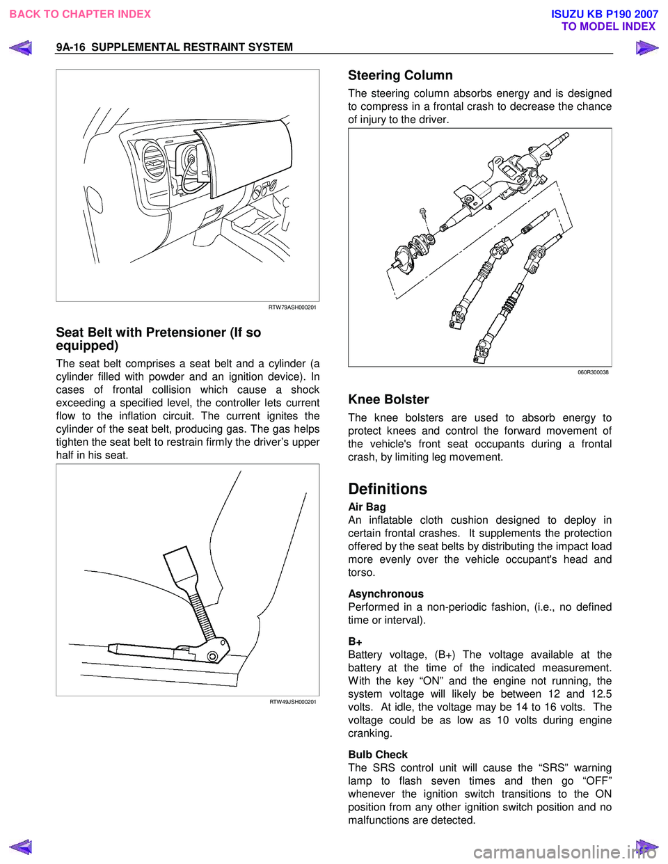
Seat Belt with Pretensioner (If so
equipped)
The seat belt comprises a seat belt and a cylinder (a
cylinder filled with powder and an ignition device). In
cases of frontal collision which cause a shock
exceeding a specified level, the controller lets current
flow to the inflation circuit. The current ignites the
cylinder of the seat belt, producing gas. The gas helps
tighten the seat belt to restrain firmly the driver’s uppe
r
half in his seat.
RTW 49JSH000201
Steering Column
The steering column absorbs energy and is designed
to compress in a frontal crash to decrease the chance
of injury to the driver.
060R300038
Knee Bolster
The knee bolsters are used to absorb energy to
protect knees and control the forward movement o
f
the vehicle's front seat occupants during a frontal
crash, by limiting leg movement.
Definitions
Air Bag
An inflatable cloth cushion designed to deploy in
certain frontal crashes. It supplements the protection
offered by the seat belts by distributing the impact load
more evenly over the vehicle occupant's head and
torso.
Asynchronous
Performed in a non-periodic fashion, (i.e., no defined
time or interval).
B+
Battery voltage, (B+) The voltage available at the
battery at the time of the indicated measurement.
W ith the key “ON” and the engine not running, the
system voltage will likely be between 12 and 12.5
volts. At idle, the voltage may be 14 to 16 volts. The
voltage could be as low as 10 volts during engine
cranking.
Bulb Check
The SRS control unit will cause the “SRS” warning
lamp to flash seven times and then go “OFF”
whenever the ignition switch transitions to the ON
position from any other ignition switch position and no
malfunctions are detected.
BACK TO CHAPTER INDEX TO MODEL INDEXISUZU KB P190 2007
Page 5652 of 6020
SUPPLEMENTAL RESTRAINT SYSTEM 9A-17
“Continuous Monitoring”
Tests are performed by the SRS control unit on the
SRS every 100 milliseconds while “Ignition 1” voltage
is in the normal operating voltage range at the SRS
control unit.
Data Link Connector (DLC)
Formerly “DLC”, a connector which allows
communication with an external computer, such as a
scan tool.
Datum Line
A base line parallel to the plane of the underbody or
frame from which all vertical measurements originate.
Deploy
To inflate the air bag.
Deployment Loops
The circuits which supply current to the air bag
assemblies to deploy the air bag.
Diagnostic Trouble Code (DTC)
Formerly “Code”, a numerical designator used by the
SRS control unit to indicate specific SRS malfunctions.
Driver Current Source
An output of the SRS control unit which applies current
into the driver air bag assembly circuit during the
“Initiator Assembly Resistance Test”.
Driver Air Bag Assembly
An assembly located in the steering wheel hub
consisting of an inflatable bag, an inflator and an
initiator.
EEPROM
Electrically Erasable Programmable Read Onl
y
Memory. Memory which retains its contents when
power is removed from the SRS control unit.
Ignition Cycle
The voltage at the SRS control unit “Ignition 1” input,
with ignition switch “ON”, is within the normal operating
voltage range for at least ten seconds before turning
the ignition switch “OFF”.
Ignition 1
A battery voltage (B+) circuit which is only powered
when the ignition switch is in the ON, or START
position.
Initiator
The electrical component inside the air bag assembl
y
which, when sufficient current flows, sets off the
chemical reaction that inflates the air bag.
“Initiator Assembly Resistance Test”
Tests are performed once for each ignition cycle when
no malfunctions are detected during “Turn–ON” o
r
“Continuous Monitoring”. This test checks for the
correct SRS control unit configuration for the vehicle,
shorts to “Ignition 1” in the deployment loops, high
resistance or opens in the “Driver Side” and
“Passenger Side” circuits and measures the resistance
of the inflator assembly consisting of 1) Initiators, 2)
SRS coil assembly (driver side only), 3) Connectors
and associated wiring.
Normal Operating Voltage Range
The voltage measured between the SRS control unit
“Ignition 1” terminals and “Ground” terminals is
between 9 and 16 volts.
Passenger Current Source
An output of the SRS control unit which applies current
into the passenger air bag assembly circuit during the
“Initiator Assembly Resistance Test”.
Passenger Air Bag Assembly
An assembly located in the front of the passenger side
of the instrument panel consisting of an inflatable bag,
an inflator and an initiator.
Scan Tool
An external computer used to read diagnostic
information from on–board computers via the data link
connector.
SRS control unit
SRS control unit which provides reserve energy to the
deployment loops, deploys the air bags when required
and performs diagnostic monitoring of all SRS
components.
Serial Data
Information representing the status of the SRS.
SRS
Supplemental Restraint System.
SRS Coil Assembly
An assembly of two current–carrying coils in the drive
r
deployment loop that allows the rotation of the steering
wheel while maintaining the continuous contact of the
driver deployment loop to the driver air bag assembly.
SRS Wiring Harness
The wires and connectors that electrically connect the
components in the SRS.
“Turn–ON”
Test which the SRS control unit performs on the SRS
once during each ignition cycle immediately afte
r
“Ignition 1” voltage is applied to the SRS control unit
and before “Continuous Monitoring”.
BACK TO CHAPTER INDEX TO MODEL INDEXISUZU KB P190 2007