2007 ISUZU KB P190 Circuit
[x] Cancel search: CircuitPage 5662 of 6020
SUPPLEMENTAL RESTRAINT SYSTEM 9A-27
5. Remove the passenger air bag assembly from the
vehicle. Refer to “Passenger Air Bag Assembl
y
Removal “.
6. Clear a space on the ground approximately 183 cm (six feet) in diameter where the fixture with
attached air bag assembly is to be placed fo
r
deployment. A paved outdoor location where there
is no activity is preferred. If an outdoor location is
not available, a space on the shop floor where
there is no activity and there is sufficient ventilation
is recommended. Ensure that no loose o
r
flammable objects are within the deployment area.
7. Place the 5-8840-2420-0 on the bench vise. This is necessary to provide sufficient stabilization o
f
the fixture during deployment.
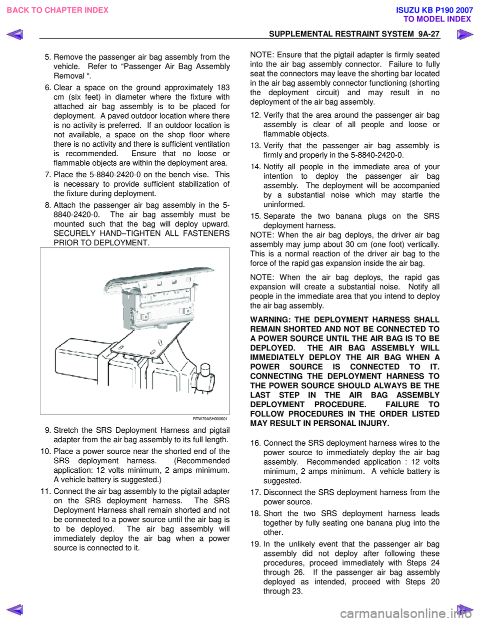
8. Attach the passenger air bag assembly in the 5- 8840-2420-0. The air bag assembly must be
mounted such that the bag will deploy upward.
SECURELY HAND–TIGHTEN ALL FASTENERS
PRIOR TO DEPLOYMENT.
RTW 79ASH000601
9. Stretch the SRS Deployment Harness and pigtail
adapter from the air bag assembly to its full length.
10. Place a power source near the shorted end of the SRS deployment harness. (Recommended
application: 12 volts minimum, 2 amps minimum.
A vehicle battery is suggested.)
11. Connect the air bag assembly to the pigtail adapte
r
on the SRS deployment harness. The SRS
Deployment Harness shall remain shorted and not
be connected to a power source until the air bag is
to be deployed. The air bag assembly will
immediately deploy the air bag when a powe
r
source is connected to it.
NOTE: Ensure that the pigtail adapter is firmly seated
into the air bag assembly connector. Failure to full
y
seat the connectors may leave the shorting bar located
in the air bag assembly connector functioning (shorting
the deployment circuit) and may result in no
deployment of the air bag assembly.
12. Verify that the area around the passenger air bag assembly is clear of all people and loose o
r
flammable objects.
13. Verify that the passenger air bag assembly is firmly and properly in the 5-8840-2420-0.
14. Notify all people in the immediate area of you
r
intention to deploy the passenger air bag
assembly. The deployment will be accompanied
by a substantial noise which may startle the
uninformed.
15. Separate the two banana plugs on the SRS deployment harness.
NOTE: W hen the air bag deploys, the driver air bag
assembly may jump about 30 cm (one foot) vertically.
This is a normal reaction of the driver air bag to the
force of the rapid gas expansion inside the air bag.
NOTE: W hen the air bag deploys, the rapid gas
expansion will create a substantial noise. Notify all
people in the immediate area that you intend to deplo
y
the air bag assembly.
WARNING: THE DEPLOYMENT HARNESS SHALL
REMAIN SHORTED AND NOT BE CONNECTED TO
A POWER SOURCE UNTIL THE AIR BAG IS TO BE
DEPLOYED. THE AIR BAG ASSEMBLY WILL
IMMEDIATELY DEPLOY THE AIR BAG WHEN
A
POWER SOURCE IS CONNECTED TO IT.
CONNECTING THE DEPLOYMENT HARNESS TO
THE POWER SOURCE SHOULD ALWAYS BE THE
LAST STEP IN THE AIR BAG ASSEMBLY
DEPLOYMENT PROCEDURE. FAILURE TO
FOLLOW PROCEDURES IN THE ORDER LISTED
MAY RESULT IN PERSONAL INJURY.
16. Connect the SRS deployment harness wires to the power source to immediately deploy the air bag
assembly. Recommended application : 12 volts
minimum, 2 amps minimum. A vehicle battery is
suggested.
17. Disconnect the SRS deployment harness from the power source.
18. Short the two SRS deployment harness leads together by fully seating one banana plug into the
other.
19. In the unlikely event that the passenger air bag assembly did not deploy after following these
procedures, proceed immediately with Steps 24
through 26. If the passenger air bag assembl
y
deployed as intended, proceed with Steps 20
through 23.
BACK TO CHAPTER INDEX TO MODEL INDEXISUZU KB P190 2007
Page 5668 of 6020
SUPPLEMENTAL RESTRAINT SYSTEM 9A-33
Inspections Required After An Accident
CAUTION: Certain SRS components must be
replaced after a frontal crash involving air bag
deployment.
In all types of accidents regardless of “Air Bag”
deployment, visually inspect all of the following
components and replace as required:
– Driver air bag assembly
– Passenger air bag assembly
– Steering wheel
– SRS coil assembly
– Steering column
– Knee bolster and instrument panel mounting attachments
– Driver seat and belt
– Passenger seat and belt
– SRS control unit
The SRS control unit should always be checked
according to “SRS Control Unit Replacement
Guidelines.”
CAUTION: Refer to “SRS control unit Replacement
Guidelines” below for important information on
SRS control unit replacement in both deployment
and non–deployment crashes.
Inspect the SRS coil assembly wiring and the steering
wheel for any sign of scorching, melting, or damage
due to excessive heat. If the coil assembly wire o
r
steering wheel is damaged, replace them. The
steering column and wheel must be dimensionall
y
checked to determine if they are damaged. Refer to
“steering wheel” in this manual.
Never use SRS parts from another vehicle. This does
not include remanufactured parts purchased from an
authorized ISUZU/GM Retailer; they may be used fo
r
SRS repairs.
Do not attempt to repair the SRS control unit, the SRS
harness, the SRS coil assembly, the air bag assembly,
the steering wheel, or the steering column. Service o
f
these items is replacement only. Verify replacement
part numbers.
CAUTION: Proper operation of the SRS control
unit and the supplemental restraint system (SRS)
requires that any repairs to the vehicle structure
return it to its original production configuration.
SRS Connectors
CAUTION: The special yellow color connectors are
used for the supplemental restraint system-air bag
circuit. When removing the cable harness, do not
pull the cables otherwise cable disconnection may
occur. When connecting the SRS connector, insert
the connector completely. Imperfect locking may
cause malfunction of the SRS circuit.
Removal
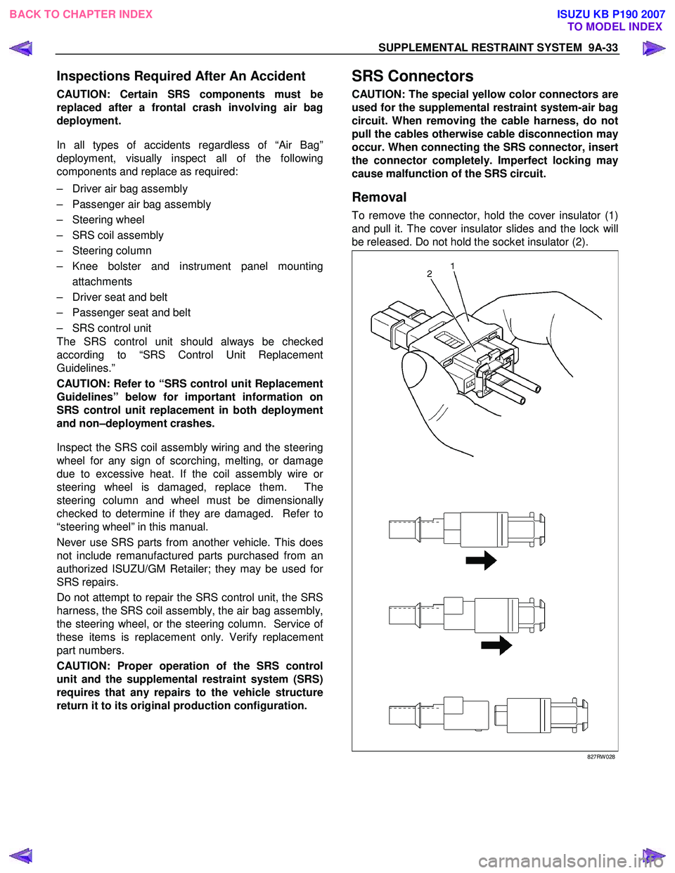
To remove the connector, hold the cover insulator (1)
and pull it. The cover insulator slides and the lock will
be released. Do not hold the socket insulator (2).
827RW 028
BACK TO CHAPTER INDEX TO MODEL INDEXISUZU KB P190 2007
Page 5680 of 6020
SUPPLEMENTAL RESTRAINT SYSTEM 9A-45
Special Tools
WARNING: TO AVOID DEPLOYMENT WHEN
TROUBLESHOOTING THE SRS, DO NOT USE
ELECTRICAL TEST EQUIPMENT SUCH AS
A
BATTERY–POWERED OR AC–POWERED
VOLTMETER, OHMMETER, ETC., OR ANY TYPE
OF ELECTRICAL EQUIPMENT OTHER THAN THAT
SPECIFIED IN THIS MANUAL. DO NOT USE AN
UNPOWERED PROBE–TYPE TESTER.
INSTRUCTIONS IN THIS MANUAL MUST BE
FOLLOWED CAREFULLY, OTHERWISE
PERSONAL INJURY MAY RESULT.
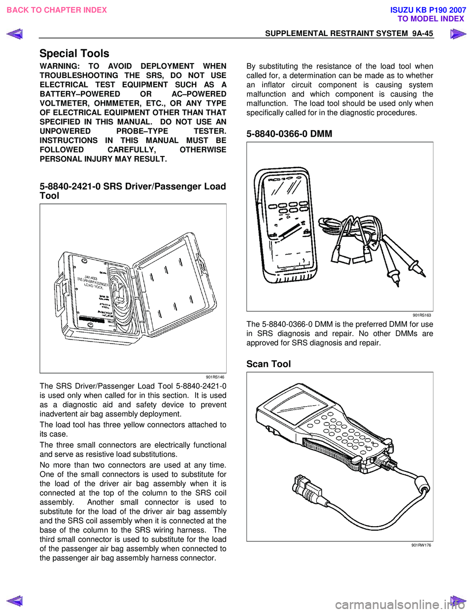
5-8840-2421-0 SRS Driver/Passenger Load
Tool
901RS146
The SRS Driver/Passenger Load Tool 5-8840-2421-0
is used only when called for in this section. It is used
as a diagnostic aid and safety device to prevent
inadvertent air bag assembly deployment.
The load tool has three yellow connectors attached to
its case.
The three small connectors are electrically functional
and serve as resistive load substitutions.
No more than two connectors are used at any time.
One of the small connectors is used to substitute fo
r
the load of the driver air bag assembly when it is
connected at the top of the column to the SRS coil
assembly. Another small connector is used to
substitute for the load of the driver air bag assembl
y
and the SRS coil assembly when it is connected at the
base of the column to the SRS wiring harness. The
third small connector is used to substitute for the load
of the passenger air bag assembly when connected to
the passenger air bag assembly harness connector.
By substituting the resistance of the load tool when
called for, a determination can be made as to whethe
r
an inflator circuit component is causing system
malfunction and which component is causing the
malfunction. The load tool should be used only when
specifically called for in the diagnostic procedures.
5-8840-0366-0 DMM
901RS163
The 5-8840-0366-0 DMM is the preferred DMM for use
in SRS diagnosis and repair. No other DMMs are
approved for SRS diagnosis and repair.
Scan Tool
901RW 176
BACK TO CHAPTER INDEX TO MODEL INDEXISUZU KB P190 2007
Page 5683 of 6020
RESTRAINT CONTROL SYSTEM 9A1-1
SECTION 9A1
RESTRAINT CONTROL SYSTEM
TABLE OF CONTENTS
PAGE
Service Precaution ............................................................................................................. ..........9A1- 2
Diagnosis In formation ......................................................................................................... ........9A1- 3
Diagnostic Procedures .......................................................................................................... ......9A1- 3
Diagnostic Codes ............................................................................................................... ..........9A1- 3
How To Read Trouble Codes ..................................................................................................... .9A1- 3
How To Clear Trouble Codes .................................................................................................... ..9A1- 3
Scan Tool Di agnostics .......................................................................................................... .......9A1- 3
Basic Knowledge Required ....................................................................................................... ..9A1- 4
Basic Electrical Circuits ..................................................................................................... .........9A1- 4
"Flash Code" Diagnostics ...................................................................................................... ....9A1- 4
DATA LIST (Tech2) .............................................................................................................. .........9A1- 5
Diagnostic Trouble Codes ....................................................................................................... ....9A1- 6
System Schematic .............................................................................................................. .........9A 1- 7
SRS Diagnostic System Check ...................................................................................................9 A1- 7
Chart A SRS control uni t Integrity Check...................................................................................9A1- 10
Chart B "SRS" Warning Lamp Comes "ON" Steady..................................................................9A1- 12
Chart C "SRS" Warning Lamp Does Not Come "ON" Steady ..................................................9A1-14
DTC B0015 (Flash Code 15) Passenger Air Ba g Squib Circuit High Resistance ...................9A1-17
DTC B0016 (Flash Code 16) Passenger Air Ba g Squib Circuit Low Resistance .....................9A1-20
DTC B0018 (Flash Code 18) Passenger Air Ba g Squib Circuit Short to GND.........................9A1-23
DTC B0019 (Flash Code 19) Passenger Air Bag Squib Circuit Short to Battery
Voltage ........................................................................................................................ ..................9A1- 26
DTC B0021 (Flash Code 21) Driver Air Ba g Squib Circuit High Resistance ............................9A1-28
DTC B0022 (Flash Code 22) Driver Air Ba g Squib Circuit Low Resistance.............................9A1-31
DTC B0025 (Flash Code 25) Driver Air Ba g Squib Circuit Short to GND ................................9A1-34
DTC B0026 (Flash Code 26) Driver Air Bag Squib Circuit Short to Battery
Voltage ........................................................................................................................ ..................9A1- 37
BACK TO CHAPTER INDEX
TO MODEL INDEX
ISUZU KB P190 2007
Page 5684 of 6020
9A1-2 RESTRAINT CONTROL SYSTEM
Service Precaution
WARNING: THIS VEHICLE HAS A SUPPLEMENTAL
RESTRAINT SYSTEM (SRS). REFER TO THE SRS
COMPONENT AND WIRING LOCATION VIEW IN
ORDER TO DETERMINE WHETHER YOU ARE
PERFORMING A SERVICE ON OR NEAR THE SRS
COMPONENTS OR THE SRS WIRING. WHEN YOU
ARE PERFORMING A SERVICE ON OR NEAR THE
SRS COMPONENTS OR THE SRS WIRING, REFER
TO THE SRS SERVICE INFORMATION. FAILURE TO
FOLLOW WARNINGS COULD RESULT IN
POSSIBLE AIR BAG DEPLOYMENT, PERSONAL
INJURY, OR OTHERWISE UNNECESSARY SRS
SYSTEM REPAIRS.
CAUTION: Always use the correct fastener in the
proper location. When you replace a fastener, use
ONLY the exact part number for that application.
ISUZU/GM will call out those fasteners that require
a replacement after removal. ISUZU/GM will also
call out the fasteners that require thread lockers o
r
thread sealant. UNLESS OTHERWISE SPECIFIED,
do not use supplemental coatings (paints, greases,
or other corrosion inhibitors) on threaded fasteners
or fastener joint interfaces. Generally, such
coatings adversely affect the fastener torque and
the joint clamping force, and may damage the
fastener. When you install fasteners, use the
correct tightening sequence and specifications.
Following these instructions can help you avoid
damage to parts and systems.
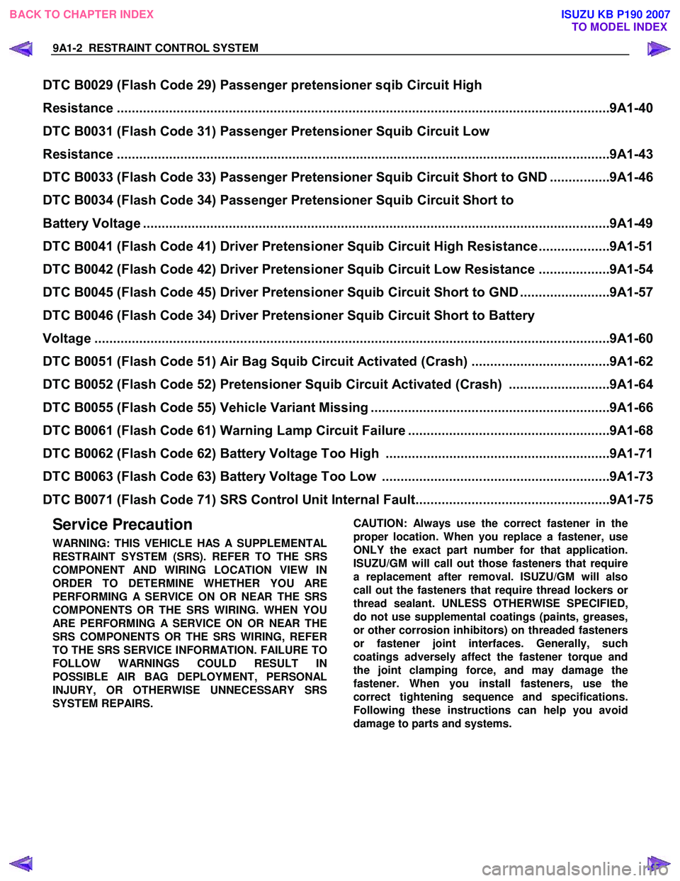
DTC B0029 (Flash Code 29) Passenger pretensioner sqib Circuit High
Resistance ..................................................................................................................... ...............9A1-40
DTC B0031 (Flash Code 31) Passenger Pretensioner Squib Circuit Low
Resistance ..................................................................................................................... ...............9A1-43
DTC B0033 (Flash Code 33) Passenger Pretensi oner Squib Circuit Short to GND ................9A1-46
DTC B0034 (Flash Code 34) Passenger Pretensioner Squib Circuit Short to
Battery Voltage ................................................................................................................ .............9A1-49
DTC B0041 (Flash Code 41) Driver Pretension er Squib Circuit High Resistance...................9A1-51
DTC B0042 (Flash Code 42) Driver Pretensi oner Squib Circuit Low Resistance ...................9A1-54
DTC B0045 (Flash Code 45) Driver Pretensi oner Squib Circuit Short to GND ........................9A1-57
DTC B0046 (Flash Code 34) Driver Pretensioner Squib Circuit Short to Battery
Voltage ........................................................................................................................ ..................9A1-60
DTC B0051 (Flash Code 51) Air Bag Squi b Circuit Activated (Crash).....................................9A1-62
DTC B0052 (Flash Code 52) Pretensioner Squib Circuit Activated (Crash) ...........................9A1-64
DTC B0055 (Flash Code 55) Ve hicle Variant Missing ................................................................9A1-66
DTC B0061 (Flash Code 61) Warnin g Lamp Circuit Failure ......................................................9A1-68
DTC B0062 (Flash Code 62) Batt ery Voltage Too High ............................................................9A1-71
DTC B0063 (Flash Code 63) Batt ery Voltage Too Low .............................................................9A1-73
DTC B0071 (Flash Code 71) SRS Cont rol Unit Internal Fault....................................................9A1-75
BACK TO CHAPTER INDEX
TO MODEL INDEX
ISUZU KB P190 2007
Page 5686 of 6020
9A1-4 RESTRAINT CONTROL SYSTEM
Basic Knowledge Required
Before using this section of the Service Manual, some
basic knowledge is required. W ithout this knowledge,
you will have trouble using the diagnostic procedures in
this section. Use care to prevent any harm or unwanted
deployment. Read all cautions in the service manual
and on warning labels attached to SRS components.
Basic Electrical Circuits
You should understand the basic theory of electricity
including series and parallel circuits, and understand
the voltage drops across series resistors. You should
know the meaning of voltage (volts), current (amps),
and resistance (ohms). You should understand what
happens in a circuit with an open or a shorted wire. You
should be able to read and understand a wiring
diagram.
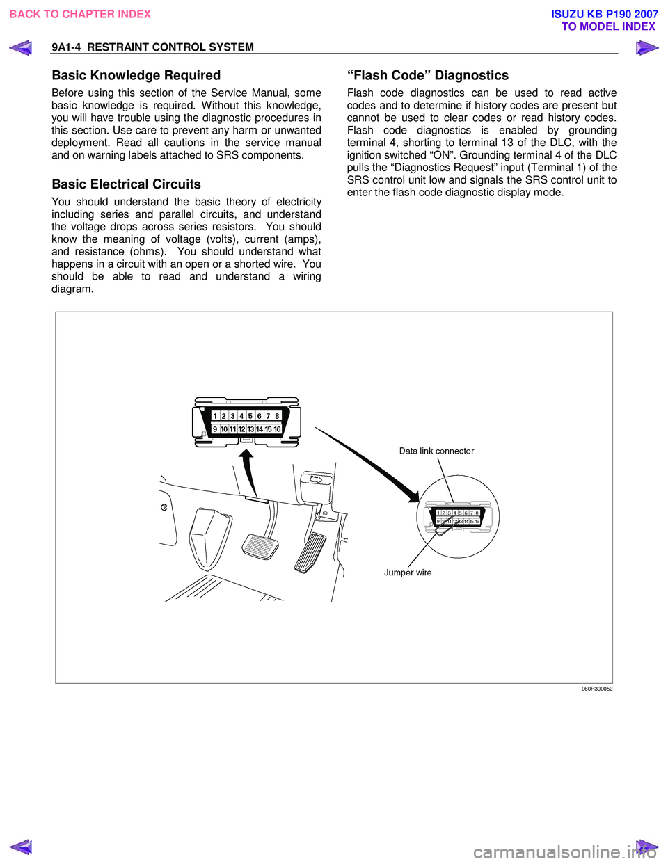
“Flash Code” Diagnostics
Flash code diagnostics can be used to read active
codes and to determine if history codes are present but
cannot be used to clear codes or read history codes.
Flash code diagnostics is enabled by grounding
terminal 4, shorting to terminal 13 of the DLC, with the
ignition switched “ON”. Grounding terminal 4 of the DLC
pulls the “Diagnostics Request” input (Terminal 1) of the
SRS control unit low and signals the SRS control unit to
enter the flash code diagnostic display mode.
060R300052
BACK TO CHAPTER INDEX TO MODEL INDEX
ISUZU KB P190 2007
Page 5687 of 6020
RESTRAINT CONTROL SYSTEM 9A1-5
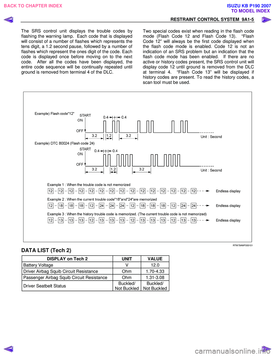
The SRS control unit displays the trouble codes b
y
flashing the warning lamp. Each code that is displayed
will consist of a number of flashes which represents the
tens digit, a 1.2 second pause, followed by a number o
f
flashes which represent the ones digit of the code. Each
code is displayed once before moving on to the next
code. After all the codes have been displayed, the
entire code sequence will be continually repeated until
ground is removed from terminal 4 of the DLC.
Two special codes exist when reading in the flash code
mode (Flash Code 12 and Flash Code 13). “Flash
Code 12” will always be the first code displayed when
the flash code mode is enabled. Code 12 is not an
indication of an SRS problem but an indication that the
flash code mode has been enabled. If there are no
active or history codes present, the SRS control unit will
display code 12 until ground is removed from the DLC
at terminal 4. “Flash Code 13” will be displayed i
f
history codes are present. To read the history codes, a
scan tool must be used.
RTW 79AMF000101
DATA LIST (Tech 2)
DISPLAY on Tech 2 UNIT VALUE
Battery Voltage
V 12.0
Driver Airbag Squib Circuit Resistance Ohm 1.70-4.33
Passenger Airbag Squib Circuit Resistance Ohm 1.31-3.08
Driver Seatbelt Status Buckled/
Not Buckled Buckled/
Not Buckled
BACK TO CHAPTER INDEX
TO MODEL INDEX
ISUZU KB P190 2007
Page 5688 of 6020
9A1-6 RESTRAINT CONTROL SYSTEM
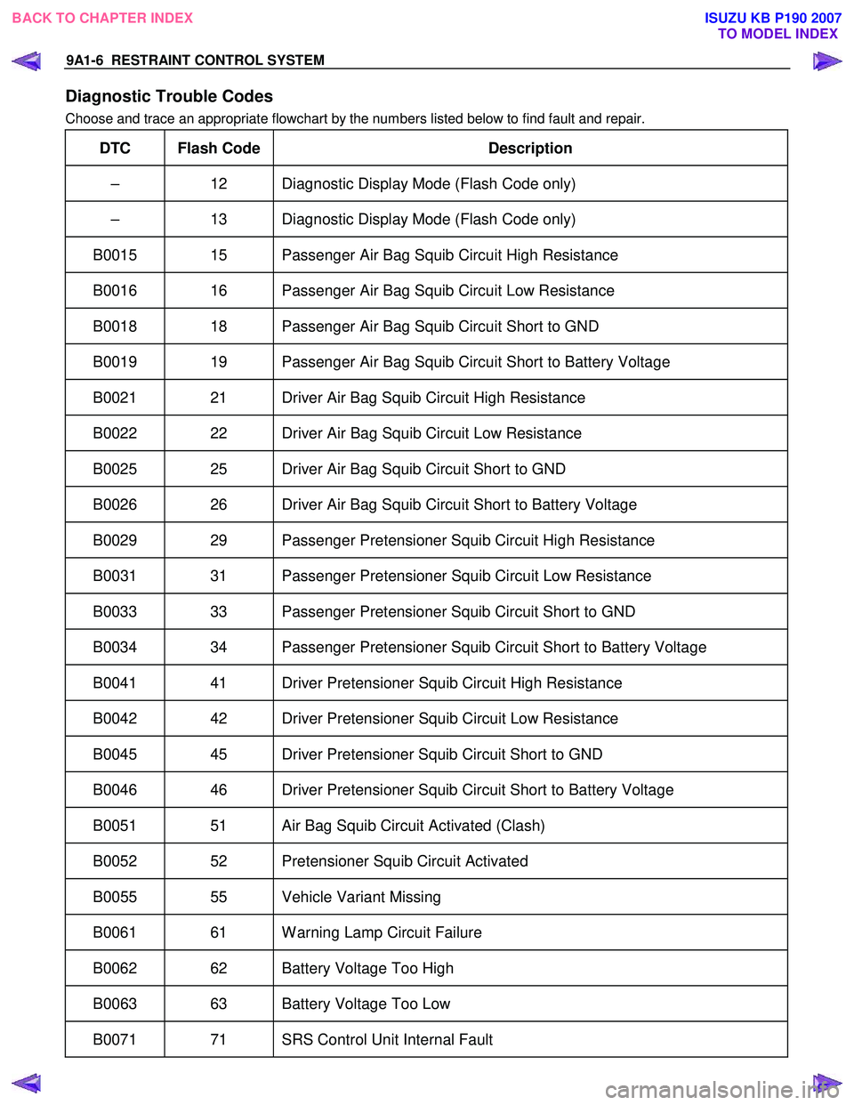
Diagnostic Trouble Codes
Choose and trace an appropriate flowchart by the numbers listed below to find fault and repair.
DTC Flash Code Description
– 12 Diagnostic Display Mode (Flash Code only)
– 13 Diagnostic Display Mode (Flash Code only)
B0015 15 Passenger Air Bag Squib Circuit High Resistance
B0016 16 Passenger Air Bag Squib Circuit Low Resistance
B0018 18 Passenger Air Bag Squib Circuit Short to GND
B0019 19 Passenger Air Bag Squib Circuit Short to Battery Voltage
B0021 21 Driver Air Bag Squib Circuit High Resistance
B0022 22 Driver Air Bag Squib Circuit Low Resistance
B0025 25 Driver Air Bag Squib Circuit Short to GND
B0026 26 Driver Air Bag Squib Circuit Short to Battery Voltage
B0029 29 Passenger Pretensioner Squib Circuit High Resistance
B0031 31 Passenger Pretensioner Squib Circuit Low Resistance
B0033 33 Passenger Pretensioner Squib Circuit Short to GND
B0034 34 Passenger Pretensioner Squib Circuit Short to Battery Voltage
B0041 41 Driver Pretensioner Squib Circuit High Resistance
B0042 42 Driver Pretensioner Squib Circuit Low Resistance
B0045 45 Driver Pretensioner Squib Circuit Short to GND
B0046 46 Driver Pretensioner Squib Circuit Short to Battery Voltage
B0051 51 Air Bag Squib Circuit Activated (Clash)
B0052 52 Pretensioner Squib Circuit Activated
B0055 55 Vehicle Variant Missing
B0061 61 Warning Lamp Circuit Failure
B0062 62 Battery Voltage Too High
B0063 63 Battery Voltage Too Low
B0071 71 SRS Control Unit Internal Fault
BACK TO CHAPTER INDEX
TO MODEL INDEX
ISUZU KB P190 2007