2007 ISUZU KB P190 odometer
[x] Cancel search: odometerPage 1305 of 6020
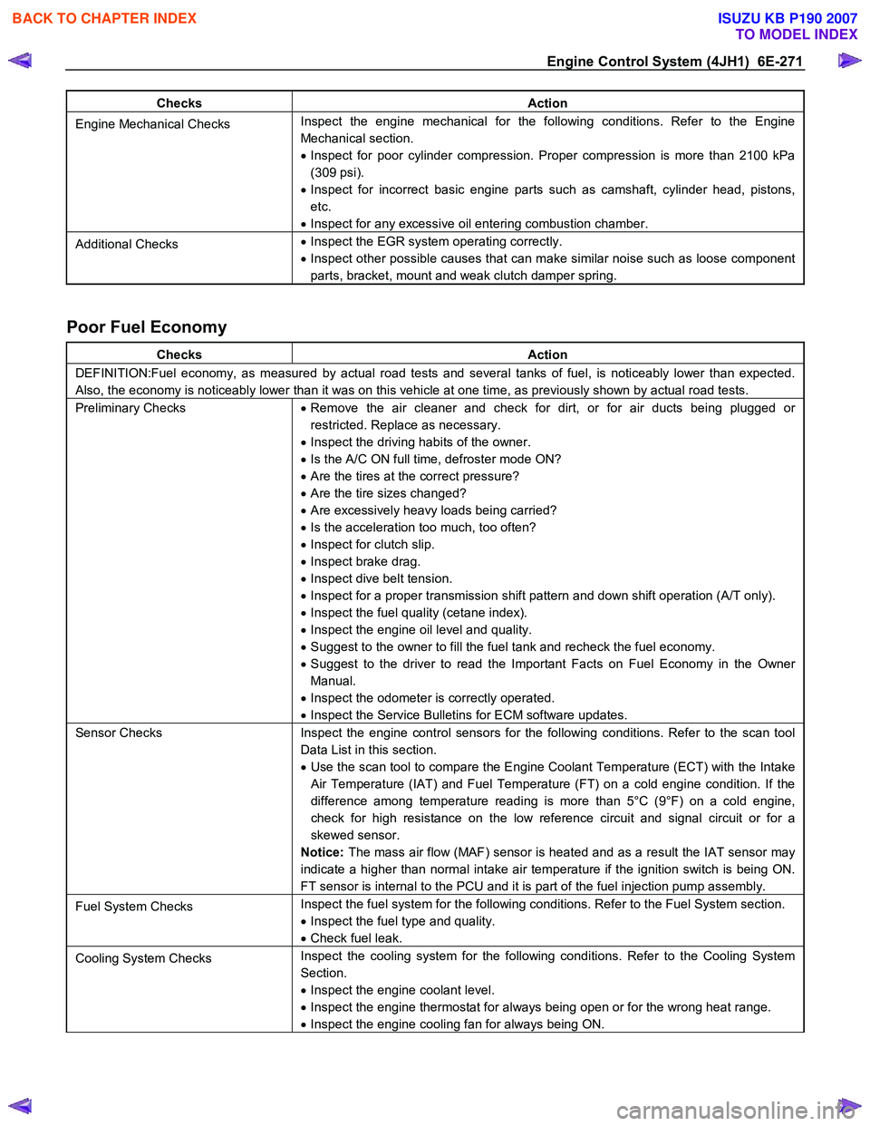
Engine Control System (4JH1) 6E-271
Checks Action
Engine Mechanical Checks Inspect the engine mechanical for the following conditions. Refer to the Engine
Mechanical section.
• Inspect for poor cylinder compression. Proper compression is more than 2100 kPa
(309 psi).
• Inspect for incorrect basic engine parts such as camshaft, cylinder head, pistons,
etc.
• Inspect for any excessive oil entering combustion chamber.
Additional Checks •
Inspect the EGR system operating correctly.
• Inspect other possible causes that can make similar noise such as loose component
parts, bracket, mount and weak clutch damper spring.
Poor Fuel Economy
Checks Action
DEFINITION:Fuel economy, as measured by actual road tests and several tanks of fuel, is noticeably lower than expected.
Also, the economy is noticeably lower than it was on this vehicle at one time, as previously shown by actual road tests.
Preliminary Checks • Remove the air cleaner and check for dirt, or for air ducts being plugged or
restricted. Replace as necessary.
• Inspect the driving habits of the owner.
• Is the A/C ON full time, defroster mode ON?
• Are the tires at the correct pressure?
• Are the tire sizes changed?
• Are excessively heavy loads being carried?
• Is the acceleration too much, too often?
• Inspect for clutch slip.
• Inspect brake drag.
• Inspect dive belt tension.
• Inspect for a proper transmission shift pattern and down shift operation (A/T only).
• Inspect the fuel quality (cetane index).
• Inspect the engine oil level and quality.
• Suggest to the owner to fill the fuel tank and recheck the fuel economy.
• Suggest to the driver to read the Important Facts on Fuel Economy in the Owner
Manual.
• Inspect the odometer is correctly operated.
• Inspect the Service Bulletins for ECM software updates.
Sensor Checks Inspect the engine control sensors for the following conditions. Refer to the scan tool
Data List in this section.
• Use the scan tool to compare the Engine Coolant Temperature (ECT) with the Intake
Air Temperature (IAT) and Fuel Temperature (FT) on a cold engine condition. If the
difference among temperature reading is more than 5°C (9°F) on a cold engine,
check for high resistance on the low reference circuit and signal circuit or for a
skewed sensor.
Notice: The mass air flow (MAF) sensor is heated and as a result the IAT sensor may
indicate a higher than normal intake air temperature if the ignition switch is being ON.
FT sensor is internal to the PCU and it is part of the fuel injection pump assembly.
Fuel System Checks Inspect the fuel system for the following conditions. Refer to the Fuel System section.
• Inspect the fuel type and quality.
• Check fuel leak.
Cooling System Checks Inspect the cooling system for the following conditions. Refer to the Cooling System
Section.
• Inspect the engine coolant level.
• Inspect the engine thermostat for always being open or for the wrong heat range.
• Inspect the engine cooling fan for always being ON.
BACK TO CHAPTER INDEX
TO MODEL INDEX
ISUZU KB P190 2007
Page 1958 of 6020
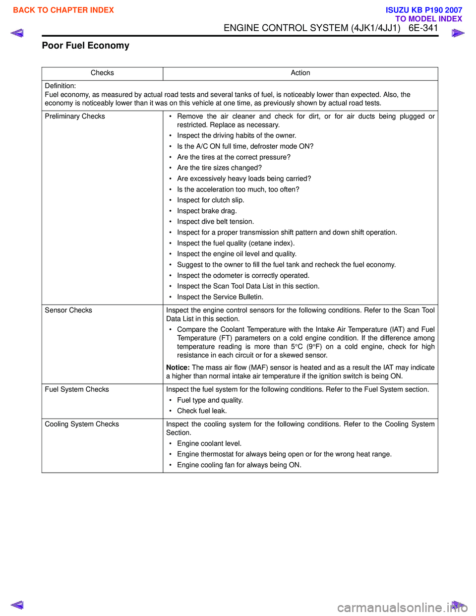
ENGINE CONTROL SYSTEM (4JK1/4JJ1) 6E-341
Poor Fuel Economy
ChecksAction
Definition:
Fuel economy, as measured by actual road tests and several tanks of fuel, is noticeably lower than expected. Also, the
economy is noticeably lower than it was on this vehicle at one time, as previously shown by actual road tests.
Preliminary Checks • Remove the air cleaner and check for dirt, or for air ducts being plugged or
restricted. Replace as necessary.
• Inspect the driving habits of the owner.
• Is the A/C ON full time, defroster mode ON?
• Are the tires at the correct pressure?
• Are the tire sizes changed?
• Are excessively heavy loads being carried?
• Is the acceleration too much, too often?
• Inspect for clutch slip.
• Inspect brake drag.
• Inspect dive belt tension.
• Inspect for a proper transmission shift pattern and down shift operation.
• Inspect the fuel quality (cetane index).
• Inspect the engine oil level and quality.
• Suggest to the owner to fill the fuel tank and recheck the fuel economy.
• Inspect the odometer is correctly operated.
• Inspect the Scan Tool Data List in this section.
• Inspect the Service Bulletin.
Sensor Checks Inspect the engine control sensors for the following conditions. Refer to the Scan Tool
Data List in this section.
• Compare the Coolant Temperature with the Intake Air Temperature (IAT) and Fuel Temperature (FT) parameters on a cold engine condition. If the difference among
temperature reading is more than 5 °C (9 °F) on a cold engine, check for high
resistance in each circuit or for a skewed sensor.
Notice: The mass air flow (MAF) sensor is heated and as a result the IAT may indicate
a higher than normal intake air temperature if the ignition switch is being ON.
Fuel System Checks Inspect the fuel system for the following conditions. Refer to the Fuel System section.
• Fuel type and quality.
• Check fuel leak.
Cooling System Checks Inspect the cooling system for the following conditions. Refer to the Cooling System
Section.
• Engine coolant level.
• Engine thermostat for always being open or for the wrong heat range.
• Engine cooling fan for always being ON.
BACK TO CHAPTER INDEX
TO MODEL INDEX
ISUZU KB P190 2007
Page 5281 of 6020
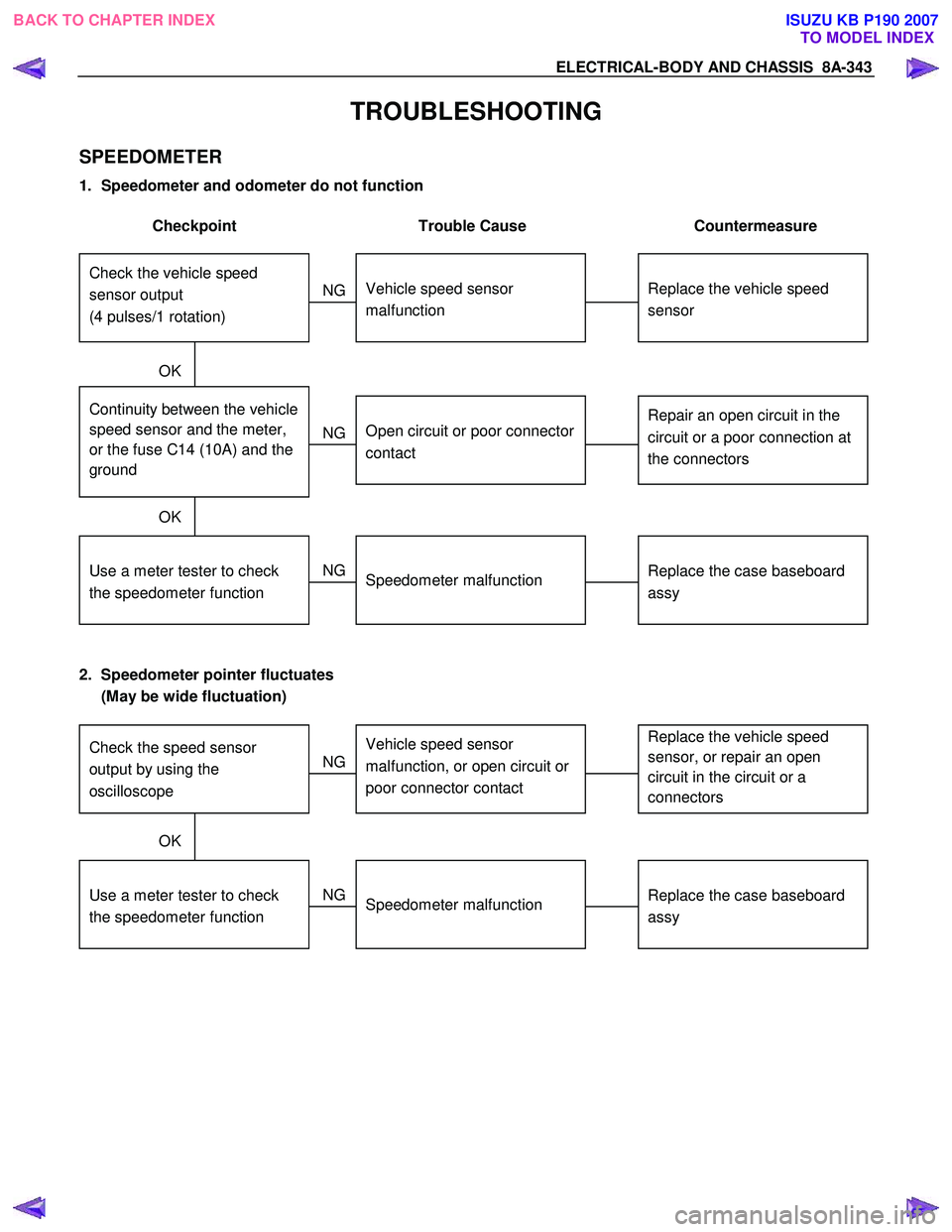
ELECTRICAL-BODY AND CHASSIS 8A-343
TROUBLESHOOTING
SPEEDOMETER
1. Speedometer and odometer do not function
Checkpoint Trouble Cause Countermeasure
Replace the vehicle speed
sensor
Vehicle speed sensor
malfunction
NG
Repair an open circuit in the
circuit or a poor connection at
the connectors Continuity between the vehicle
speed sensor and the meter,
or the fuse C14 (10A) and the
ground
Open circuit or poor connector
contact
Replace the case baseboard
assy
Use a meter tester to check
the speedometer function
Speedometer malfunction
NG
NG
OK
OK
Check the vehicle speed
sensor output
(4 pulses/1 rotation)
2. Speedometer pointer fluctuates
(May be wide fluctuation)
Replace the vehicle speed
sensor, or repair an open
circuit in the circuit or a
connectors Vehicle speed sensor
malfunction, or open circuit or
poor connector contact
NG
Replace the case baseboard
assy
Use a meter tester to check
the speedometer function
Speedometer malfunction
NG
OK
Check the speed sensor
output by using the
oscilloscope
BACK TO CHAPTER INDEX TO MODEL INDEXISUZU KB P190 2007
Page 5282 of 6020
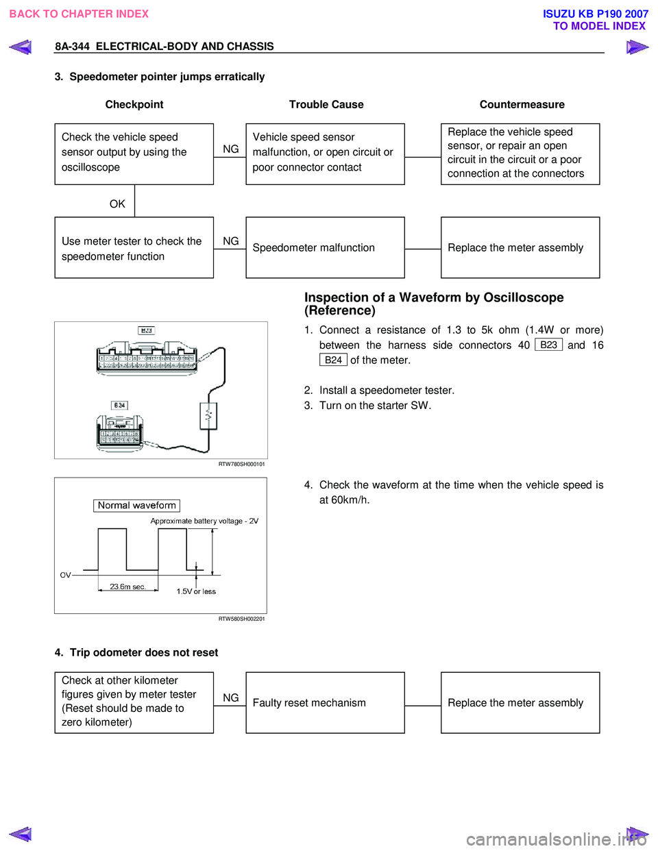
8A-344 ELECTRICAL-BODY AND CHASSIS
3. Speedometer pointer jumps erratically
Checkpoint Trouble Cause Countermeasure
Replace the vehicle speed
sensor, or repair an open
circuit in the circuit or a poor
connection at the connectors Vehicle speed sensor
malfunction, or open circuit or
poor connector contact
NG
Replace the meter assembly
Use meter tester to check the
speedometer function
Speedometer malfunction
NG
OK
Check the vehicle speed
sensor output by using the
oscilloscope
Inspection of a Waveform by Oscilloscope
(Reference)
RTW 780SH000101
1. Connect a resistance of 1.3 to 5k ohm (1.4W or more)
between the harness side connectors 40
B23 and 16
B24 of the meter.
2. Install a speedometer tester.
3. Turn on the starter SW .
RTW 580SH002201
4. Check the waveform at the time when the vehicle speed is
at 60km/h.
4. Trip odometer does not reset
Replace the meter assembly
Faulty reset mechanism
NG
Check at other kilometer
figures given by meter tester
(Reset should be made to
zero kilometer)
BACK TO CHAPTER INDEX
TO MODEL INDEXISUZU KB P190 2007
Page 5300 of 6020
8A-362 ELECTRICAL-BODY AND CHASSIS
Tachometer Off-Vehicle Inspection
Remove the tachometer from the meter assembly and
measure the resistance value and the current consumption
between each terminal.
SELF DIAGNOSTIC FUNCTION
Check that the speedometer, tachometer, fuel gauge, and
temperature gauge operate properly.
821R300033
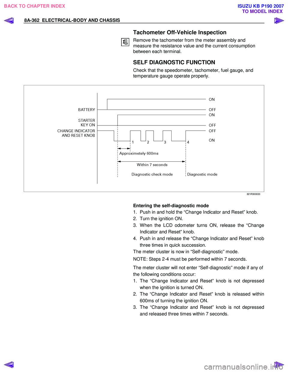
Entering the self-diagnostic mode
1. Push in and hold the “Change Indicator and Reset” knob.
2. Turn the ignition ON.
3. W hen the LCD odometer turns ON, release the “Change Indicator and Reset” knob.
4. Push in and release the “Change Indicator and Reset” knob three times in quick succession.
The meter cluster is now in “Self-diagnostic” mode.
NOTE: Steps 2-4 must be performed within 7 seconds.
The meter cluster will not enter “Self-diagnostic” mode if any of
the following conditions occur:
1. The “Change Indicator and Reset” knob is not depressed when the ignition is turned ON.
2. The “Change Indicator and Reset” knob is released within 600ms of turning the ignition ON.
3. The “Change Indicator and Reset” knob is not depressed and released three times within 7 seconds.
BACK TO CHAPTER INDEX TO MODEL INDEXISUZU KB P190 2007
Page 5301 of 6020
ELECTRICAL-BODY AND CHASSIS 8A-363
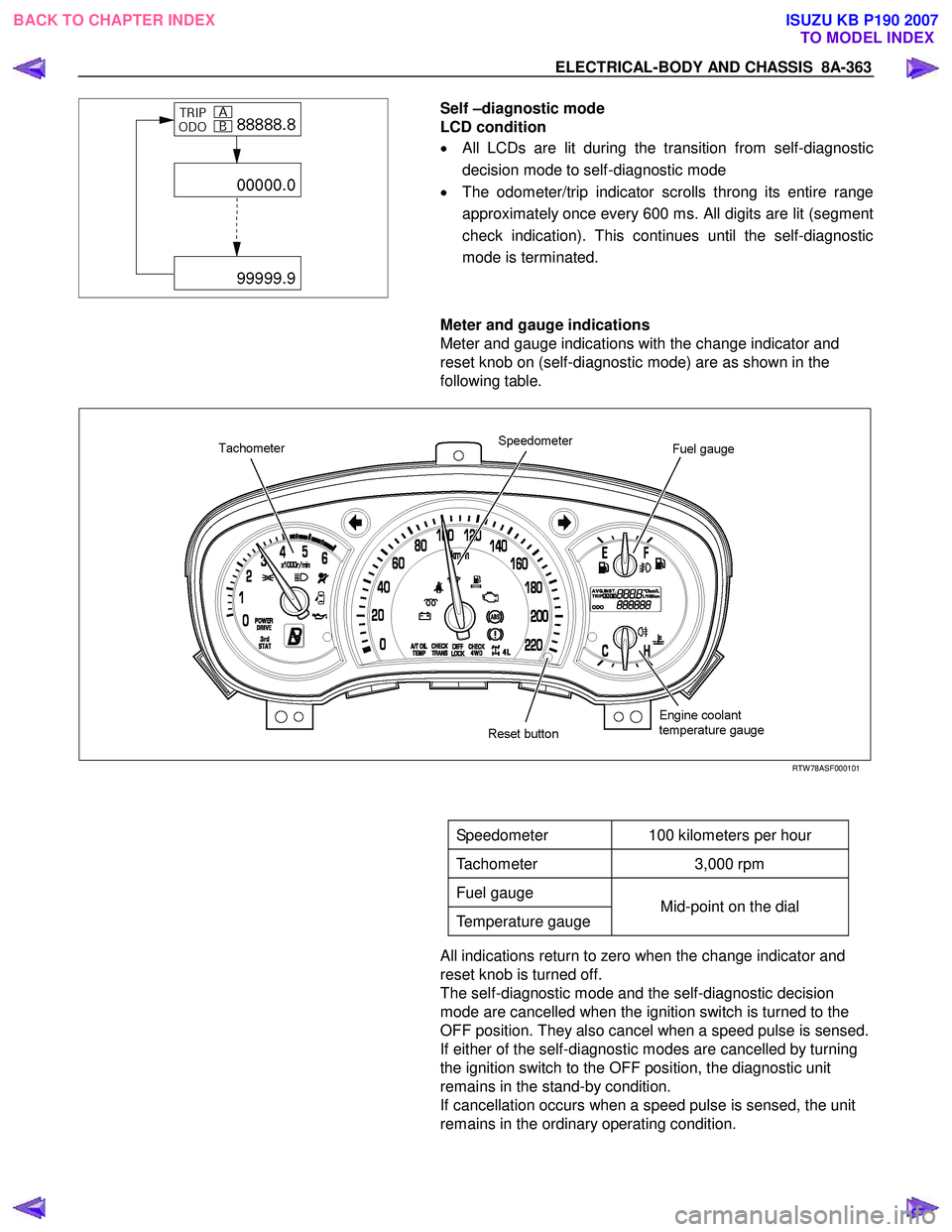
Self –diagnostic mode
LCD condition
• All LCDs are lit during the transition from self-diagnostic
decision mode to self-diagnostic mode
• The odometer/trip indicator scrolls throng its entire range
approximately once every 600 ms. All digits are lit (segment
check indication). This continues until the self-diagnostic
mode is terminated.
Meter and gauge indications
Meter and gauge indications with the change indicator and
reset knob on (self-diagnostic mode) are as shown in the
following table.
RTW 78ASF000101
Speedometer 100 kilometers per hour
Tachometer 3,000 rpm
Fuel gauge
Temperature gauge Mid-point on the dial
All indications return to zero when the change indicator and
reset knob is turned off.
The self-diagnostic mode and the self-diagnostic decision
mode are cancelled when the ignition switch is turned to the
OFF position. They also cancel when a speed pulse is sensed.
If either of the self-diagnostic modes are cancelled by turning
the ignition switch to the OFF position, the diagnostic unit
remains in the stand-by condition.
If cancellation occurs when a speed pulse is sensed, the unit
remains in the ordinary operating condition.
BACK TO CHAPTER INDEX TO MODEL INDEXISUZU KB P190 2007