2007 ISUZU KB P190 load capacity
[x] Cancel search: load capacityPage 3641 of 6020

Battery Page 6D1-3–1
6D1-3
Battery – V6
ATTENTION
Before performing any service operation or other procedure described in this Section, refer to 1.1
WARNING, CAUTION and NOTES for correct workshop practices with regard to safety and/or property
damage.
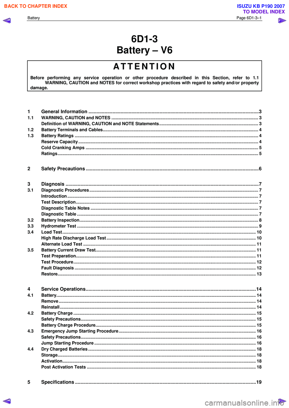
1 General Information ............................................................................................................ ...................3
1.1 WARNING, CAUTION and NOTES ..................................................................................................... ................... 3
Definition of WARNING, CAUTION and NOTE Statements ............................................................................. .... 3
1.2 Battery Terminals and Cables............................................................................................................................... 4
1.3 Battery Ratings ...................................................................................................................................................... 4
Reserve Capacity ............................................................................................................... .................................... 4
Cold Cranking Amps ............................................................................................................................................. 5
Ratings.................................................................................................................................................................... 5
2 Safety Precautions .................................................................................................................................6
3 Diagnosis ................................................................................................................................................7
3.1 Diagnostic Procedures .......................................................................................................................................... 7
Introduction ............................................................................................................................................................ 7
Test Description ..................................................................................................................................................... 7
Diagnostic Table Notes ......................................................................................................................................... 7
Diagnostic Table .................................................................................................................................................... 7
3.2 Battery Inspection.................................................................................................................................................. 8
3.3 Hydrometer Test .................................................................................................................................................... 9
3.4 Load Test ...................................................................................................................... ........................................ 10
High Rate Discharge Load Test .................................................................................................. ........................ 10
Alternate Load Test ............................................................................................................................................. 11
3.5 Battery Current Draw Test...................................................................................................... ............................. 11
Test Preparation................................................................................................................................................... 11
Test Procedure ..................................................................................................................................................... 12
Fault Diagnosis .................................................................................................................................................... 12
Restore.................................................................................................................................................................. 13
4 Service Operations ...............................................................................................................................14
4.1 Battery................................................................................................................................................................... 14
Remove ......................................................................................................................... ........................................ 14
Reinstall ................................................................................................................................................................ 14
4.2 Battery Charge ................................................................................................................. .................................... 15
Safety Precautions............................................................................................................. .................................. 15
Battery Charge Procedure....................................................................................................... ............................ 15
4.3 Emergency Jump Starting Procedure .............................................................................................. .................. 16
Safety Precautions............................................................................................................................................... 16
Jump Starting Procedure ........................................................................................................ ............................ 16
4.4 Dry Charged Batteries ......................................................................................................................................... 18
Storage.................................................................................................................................................................. 18
Activation..................................................................................................................... ......................................... 18
Post Activation Tests .......................................................................................................... ................................ 18
5 Specifications .......................................................................................................................................19
BACK TO CHAPTER INDEX
TO MODEL INDEX
ISUZU KB P190 2007
Page 3644 of 6020

Battery Page 6D1-3–4
• Clarify a procedure,
• Present additional information for accomplishing a procedure,
• Give insight into the reasons for performing a procedure in the recommended manner, and / or
Present information that gives the technician the benefit of past experience in accomplishing a procedure with greater
ease.
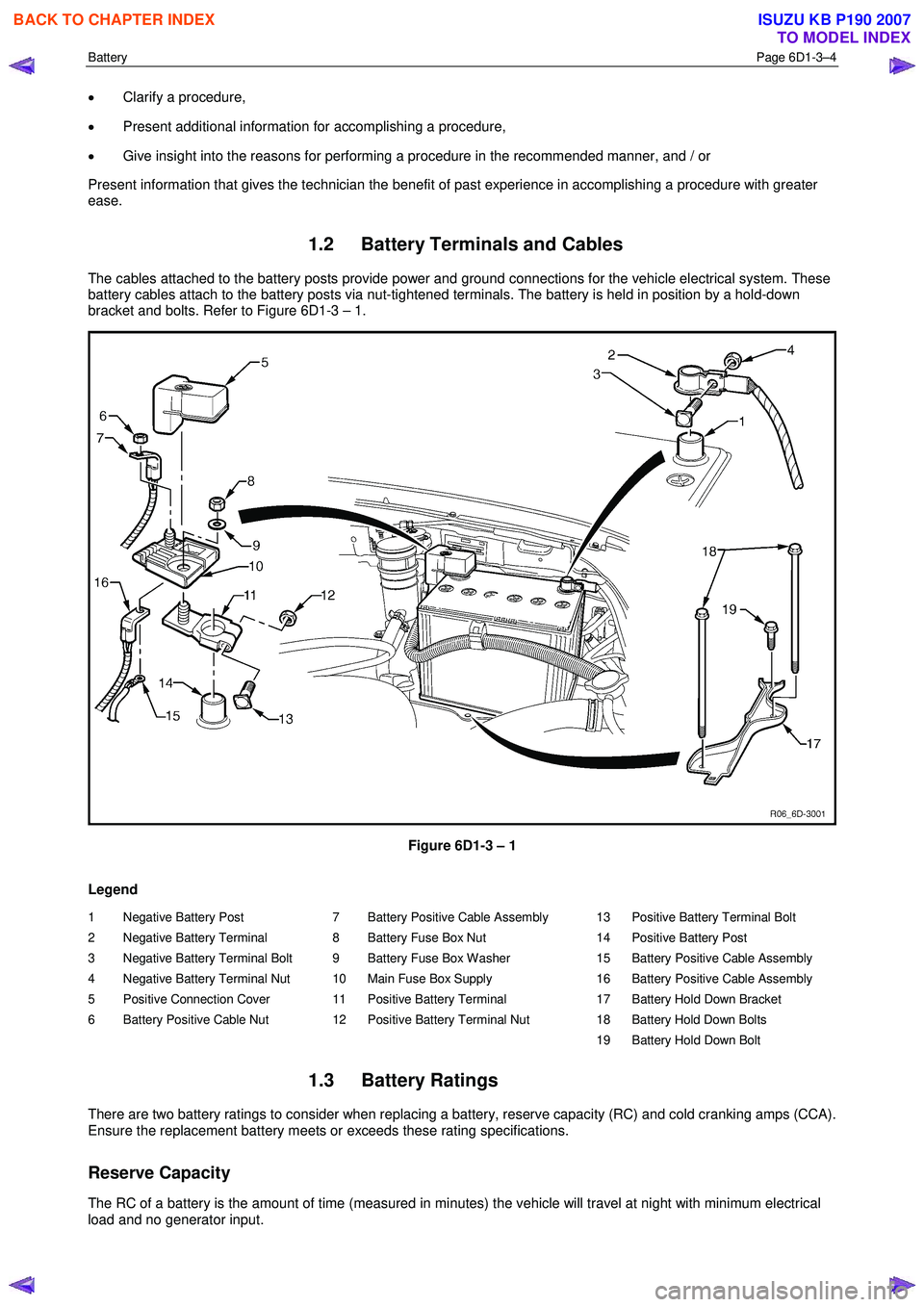
1.2 Battery Terminals and Cables
The cables attached to the battery posts provide power and ground connections for the vehicle electrical system. These
battery cables attach to the battery posts via nut-tightened terminals. The battery is held in position by a hold-down
bracket and bolts. Refer to Figure 6D1-3 – 1.
Figure 6D1-3 – 1
Legend
1 Negative Battery Post
2 Negative Battery Terminal
3 Negative Battery Terminal Bolt
4 Negative Battery Terminal Nut
5 Positive Connection Cover
6 Battery Positive Cable Nut 7 Battery Positive Cable Assembly
8 Battery Fuse Box Nut
9 Battery Fuse Box Washer
10 Main Fuse Box Supply
11 Positive Battery Terminal
12 Positive Battery Terminal Nut 13 Positive Battery Terminal Bolt
14 Positive Battery Post
15 Battery Positive Cable Assembly
16 Battery Positive Cable Assembly
17 Battery Hold Down Bracket
18 Battery Hold Down Bolts
19 Battery Hold Down Bolt
1.3 Battery Ratings
There are two battery ratings to consider when replacing a battery, reserve capacity (RC) and cold cranking amps (CCA).
Ensure the replacement battery meets or exceeds these rating specifications.
Reserve Capacity
The RC of a battery is the amount of time (measured in minutes) the vehicle will travel at night with minimum electrical
load and no generator input.
BACK TO CHAPTER INDEX
TO MODEL INDEX
ISUZU KB P190 2007
Page 3773 of 6020

Automatic Transmission – 4L60E – General Information Page 7C1–13
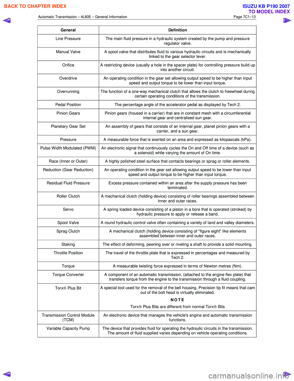
General Definition
Line Pressure The main fluid pressure in a hydraulic system created by the pump and pressure
regulator valve.
Manual Valve A spool valve that distributes fluid to various hydraulic circuits and is mechanically
linked to the gear selector lever.
Orifice A restricting device (usually a hole in the spacer plate) for controlling pressure build up
into another circuit.
Overdrive An operating condition in the gear set allowing output speed to be higher than input
speed and output torque to be lower than input torque.
Overrunning The function of a one-way mechanical clutch that allows the clutch to freewheel during certain operating conditions of the transmission.
Pedal Position The percentage angle of the accelerator pedal as displayed by Tech 2.
Pinion Gears Pinion gears (housed in a carrier) that are in constant mesh with a circumferential
internal gear and centralised sun gear.
Planetary Gear Set An assembly of gears that consists of an internal gear, planet pinion gears with a carrier, and a sun gear.
Pressure A measurable force that is exerted on an area and expressed as kilopascals (kPa).
Pulse Width Modulated (PW M) An electronic signal that continuously cycles the On and Off time of a device (such as
a solenoid) while varying the amount of On time.
Race (Inner or Outer) A highly polished steel surface that contacts bearings or sprag or roller elements.
Reduction (Gear Reduction) An operating condition in the gear set allowing output speed to be lower than input speed and output torque to be higher than input torque.
Residual Fluid Pressure Excess pressure contained within an area after the supply pressure has been terminated.
Roller Clutch A mechanical clutch (holding device) consisting of roller bearings assembled between inner and outer races.
Servo A spring loaded device consisting of a piston in a bore that is operated (stroked) by
hydraulic pressure to apply or release a band.
Spool Valve A round hydraulic control valve often containing a variety of land and valley diameters.
Sprag Clutch A mechanical clutch (holding device consisting of "figure eight" like elements
assembled between inner and outer races.
Staking The effect of deforming, peening over or riveting a shaft to provide a solid mounting.
Throttle Position The travel of the throttle plate that is expressed in percentages and measured by
Tech 2.
Torque A measurable twisting force expressed in terms of Newton metres (Nm).
Torque Converter A component of an automatic transmission, (attached to the engine flex plate) that
transfers torque from the engine to the transmission through a fluid coupling.
Torx Plus Bit A special tool used for the removal of the bell housing. Precision tip fit means that cam
out of the bolt head is virtually eliminated.
NOTE
Torx
Plus Bits are different from normal Torx
Bits
Transmission Control Module
(TCM) An electronic device that manages the vehicle's engine and automatic transmission
functions.
Variable Capacity Pump The device that provides fluid for operating the hydraulic circuits in the transmission. The amount of fluid supplied varies depending on vehicle operating conditions.
BACK TO CHAPTER INDEX
TO MODEL INDEX
ISUZU KB P190 2007
Page 4424 of 6020

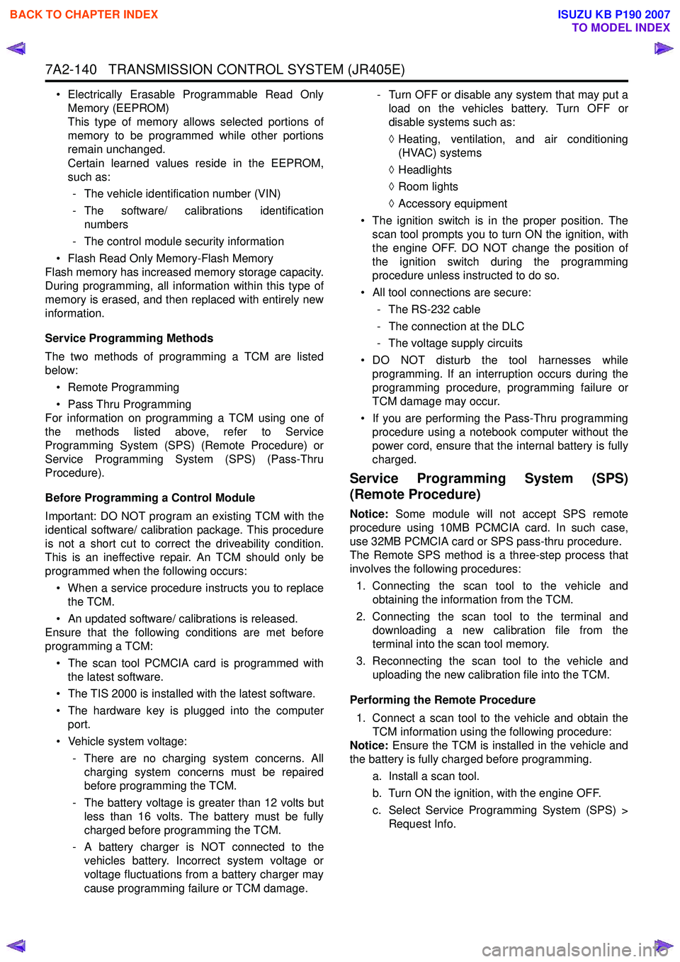
7A2-140 TRANSMISSION CONTROL SYSTEM (JR405E)
• Electrically Erasable Programmable Read OnlyMemory (EEPROM)
This type of memory allows selected portions of
memory to be programmed while other portions
remain unchanged.
Certain learned values reside in the EEPROM,
such as:
- The vehicle identification number (VIN)
- The software/ calibrations identification numbers
- The control module security information
• Flash Read Only Memory-Flash Memory
Flash memory has increased memory storage capacity.
During programming, all information within this type of
memory is erased, and then replaced with entirely new
information.
Service Programming Methods
The two methods of programming a TCM are listed
below:
• Remote Programming
• Pass Thru Programming
For information on programming a TCM using one of
the methods listed above, refer to Service
Programming System (SPS) (Remote Procedure) or
Service Programming System (SPS) (Pass-Thru
Procedure).
Before Programming a Control Module
Important: DO NOT program an existing TCM with the
identical software/ calibration package. This procedure
is not a short cut to correct the driveability condition.
This is an ineffective repair. An TCM should only be
programmed when the following occurs:
• When a service procedure instructs you to replace the TCM.
• An updated software/ calibrations is released.
Ensure that the following conditions are met before
programming a TCM:
• The scan tool PCMCIA card is programmed with the latest software.
• The TIS 2000 is installed with the latest software.
• The hardware key is plugged into the computer port.
• Vehicle system voltage:
- There are no charging system concerns. Allcharging system concerns must be repaired
before programming the TCM.
- The battery voltage is greater than 12 volts but less than 16 volts. The battery must be fully
charged before programming the TCM.
- A battery charger is NOT connected to the vehicles battery. Incorrect system voltage or
voltage fluctuations from a battery charger may
cause programming failure or TCM damage. - Turn OFF or disable any system that may put a
load on the vehicles battery. Turn OFF or
disable systems such as:
◊ Heating, ventilation, and air conditioning
(HVAC) systems
◊ Headlights
◊ Room lights
◊ Accessory equipment
• The ignition switch is in the proper position. The scan tool prompts you to turn ON the ignition, with
the engine OFF. DO NOT change the position of
the ignition switch during the programming
procedure unless instructed to do so.
• All tool connections are secure:
- The RS-232 cable
- The connection at the DLC
- The voltage supply circuits
• DO NOT disturb the tool harnesses while programming. If an interruption occurs during the
programming procedure, programming failure or
TCM damage may occur.
• If you are performing the Pass-Thru programming procedure using a notebook computer without the
power cord, ensure that the internal battery is fully
charged.
Service Programming System (SPS)
(Remote Procedure)
Notice: Some module will not accept SPS remote
procedure using 10MB PCMCIA card. In such case,
use 32MB PCMCIA card or SPS pass-thru procedure.
The Remote SPS method is a three-step process that
involves the following procedures:
1. Connecting the scan tool to the vehicle and obtaining the information from the TCM.
2. Connecting the scan tool to the terminal and downloading a new calibration file from the
terminal into the scan tool memory.
3. Reconnecting the scan tool to the vehicle and uploading the new calibration file into the TCM.
Performing the Remote Procedure 1. Connect a scan tool to the vehicle and obtain the TCM information using the following procedure:
Notice: Ensure the TCM is installed in the vehicle and
the battery is fully charged before programming.
a. Install a scan tool.
b. Turn ON the ignition, with the engine OFF.
c. Select Service Programming System (SPS) > Request Info.
BACK TO CHAPTER INDEX
TO MODEL INDEX
ISUZU KB P190 2007