Page 5079 of 6020

ELECTRICAL-BODY AND CHASSIS 8A-141
REMOVAL AND INSTALLATION
ECM (ENGINE CONTROL MODULE);
4JH1-TC
Removal
1. Remove the passenger side front seat – refer to Section 10
CAB.
2. Remove the passenger side front door opening scuff plate.
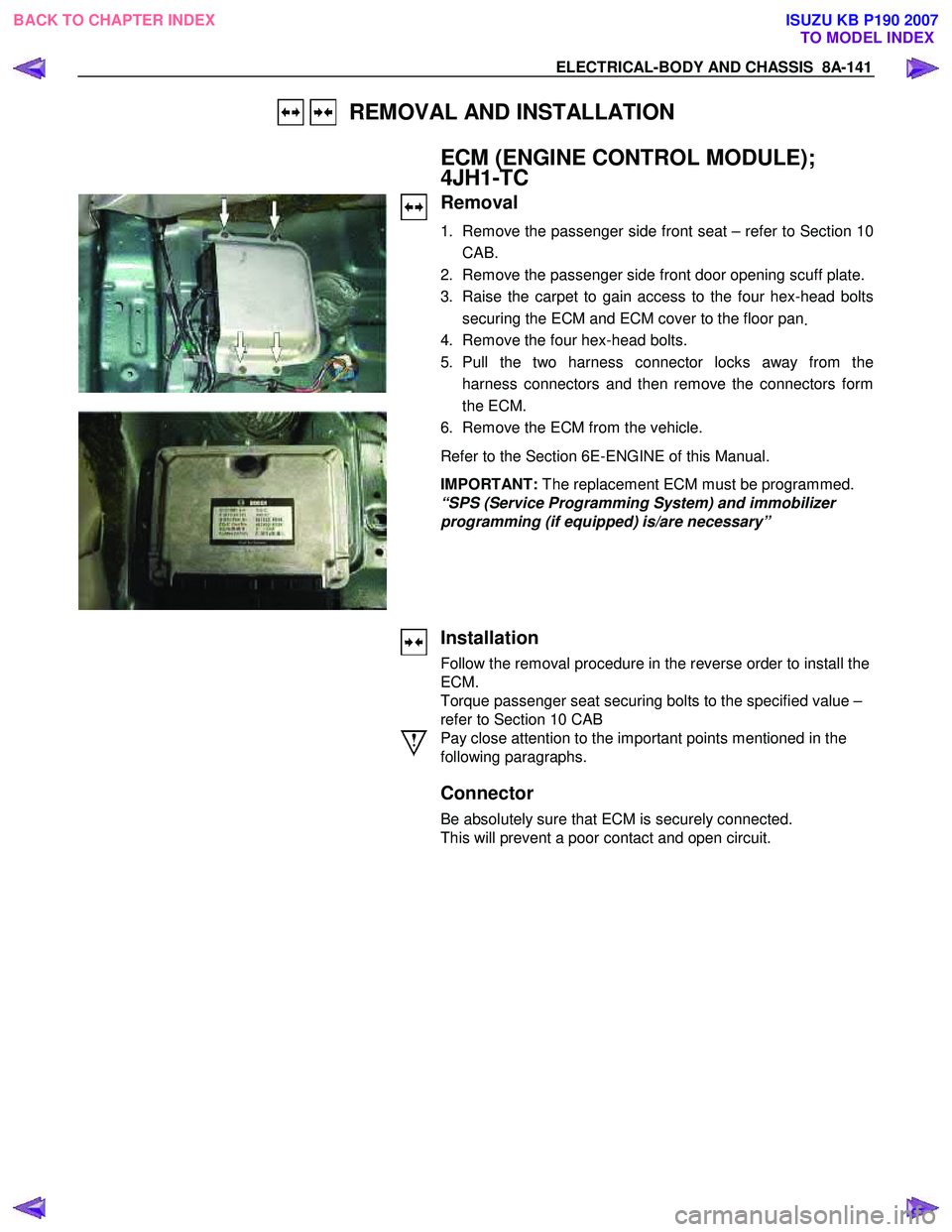
3. Raise the carpet to gain access to the four hex-head bolts securing the ECM and ECM cover to the floor pan .
4. Remove the four hex-head bolts.
5. Pull the two harness connector locks away from the harness connectors and then remove the connectors form
the ECM.
6. Remove the ECM from the vehicle.
Refer to the Section 6E-ENGINE of this Manual.
IMPORTANT: The replacement ECM must be programmed.
“SPS (Service Programming System) and immobilizer
programming (if equipped) is/are necessary”
Installation
Follow the removal procedure in the reverse order to install the
ECM.
Torque passenger seat securing bolts to the specified value –
refer to Section 10 CAB
Pay close attention to the important points mentioned in the
following paragraphs.
Connector
Be absolutely sure that ECM is securely connected.
This will prevent a poor contact and open circuit.
BACK TO CHAPTER INDEX TO MODEL INDEXISUZU KB P190 2007
Page 5174 of 6020
8A-236 ELECTRICAL-BODY AND CHASSIS
HIGH MOUNTED STOPLIGHT
Remove the bulb socket
1. Remove the high mounted stoplight ASM. • Remove the screws.
• Disconnect the connector.
2. Remove the bulb socket.
• Turn the bulb
1 counterclockwise to remove it.
Installation
Follow the removal procedure in the reverse order to install the
rear combination light.
Pay close attention to the important points mentioned in the
following paragraphs.
Bulb
Be absolutely sure that each bulb is correctly installed.
This will prevent a poor contact and an open circuit.
DOOR MIRROR - TURN SIGNAL LIGHT
Removal
1. Pull the lower outside corner of the mirror toward you.
RUW 580SH000701
2. Press the blade of an ordinary screwdriver (2) into the
mirror outside groove near the mirror base hole (1).
BACK TO CHAPTER INDEX TO MODEL INDEXISUZU KB P190 2007
Page 5175 of 6020

ELECTRICAL-BODY AND CHASSIS 8A-237
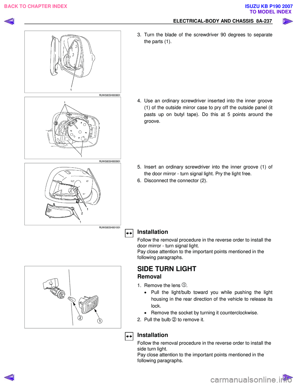
RUW 580SH000801
3. Turn the blade of the screwdriver 90 degrees to separate
the parts (1).
RUW 580SH000901
4. Use an ordinary screwdriver inserted into the inner groove
(1) of the outside mirror case to pry off the outside panel (it
pasts up on butyl tape). Do this at 5 points around the
groove.
RUW 580SH001001
5. Insert an ordinary screwdriver into the inner groove (1) of
the door mirror - turn signal light. Pry the light free.
6. Disconnect the connector (2).
Installation
Follow the removal procedure in the reverse order to install the
door mirror - turn signal light.
Pay close attention to the important points mentioned in the
following paragraphs.
SIDE TURN LIGHT
Removal
1. Remove the lens 1.
• Pull the light/bulb toward you while pushing the light
housing in the rear direction of the vehicle to release its
lock.
• Remove the socket by turning it counterclockwise.
2. Pull the bulb
2 to remove it.
Installation
Follow the removal procedure in the reverse order to install the
side turn light.
Pay close attention to the important points mentioned in the
following paragraphs.
BACK TO CHAPTER INDEX TO MODEL INDEXISUZU KB P190 2007
Page 5199 of 6020
ELECTRICAL-BODY AND CHASSIS 8A-261
DOOR SWITCH
Removal
1. Disconnect the battery ground cable.
2. Loosen the screw
1.
3. Remove the door switch
2.
4. Disconnect the door switch connector
3.
Installation
Follow the removal procedure in the reverse order to install the
spot light.
Pay close attention to the important points mentioned in the
following paragraphs.
Connector
Be absolutely sure that the door switch connector is securely
connected.
This will prevent a poor contact and an open circuit.
SPOTLIGHT (MAP Light)
Removal
1. Grasp the spotlight housing 1 with both hands.
Pull the housing straight down.
This will release the clip.
2. Disconnect the connector
2.
3. Turn socket
3 counterclockwise to remove it.
BACK TO CHAPTER INDEX TO MODEL INDEXISUZU KB P190 2007
Page 5201 of 6020
ELECTRICAL-BODY AND CHASSIS 8A-263
INSPECTION AND REPAIR
R9 R10
R1 R6
DOOR SWITCH
Door Switch Connections
Connector
SW No.
R9
R10
R1 R6
position Terminal No.
1 Body Ground
PUSHED
RELEASED
W arning function Operational conditions
Key left in starter switch The buzzer sounds when both the key remind switch and the front door
switch-driver side are turned on.
To stop the sound of the buzzer, turn OFF the starter switch and remove the
key from the starter switch.
Lighting switch left on The buzzer sounds when the starter switch is turned from the “ON” to “OFF”
position while the lighting switch is ON position.
To stop the sound of the buzzer, turn OFF the lighting switch.
B62 B63
KEY REMIND SWITCH (STARTER
SWITCH)
Switch Connections
Connector
No. B63
Starter Terminal
switch key position No.
2 4
Removed
OFF
ACC Inserted
ON
START
LOCK
BACK TO CHAPTER INDEX TO MODEL INDEXISUZU KB P190 2007
Page 5324 of 6020
8A-386 ELECTRICAL-BODY AND CHASSIS
POWER DOOR LOCK
PARTS LOCATION (RHD)
RTW 78AXF039301 & RTW 78AXF045501
BACK TO CHAPTER INDEX
TO MODEL INDEXISUZU KB P190 2007
Page 5345 of 6020
ELECTRICAL-BODY AND CHASSIS 8A-407
TROUBLESHOOTING
QUICK CHART FOR CHECK POINTS
Check Points Fuse C21
(20A) Power
Window &
Door Lock Switch Door
Lock
Switch Key Cylinder
switch Door Lock Actuator
Cable
Trouble Mode Driver’s
side Driver’s
side D/S P/S Passen
ger’s side RR-RH RR-LH
Harness
1. All the doors do not
lock and unlock
2. All the doors do not get locked (or
unlocked)
3. Driver’s side door
does not get locked
(or unlocked)
4. FRT passenger’s side
door does not get
locked (or unlocked)
5. RR door-RH does not
get locked (or
unlocked)
6. RR door-LH does not
get locked (or
unlocked)
7. Door lock does not
operate when
operating from the
driver’s seat side
BACK TO CHAPTER INDEX
TO MODEL INDEXISUZU KB P190 2007
Page 5346 of 6020

8A-408 ELECTRICAL-BODY AND CHASSIS
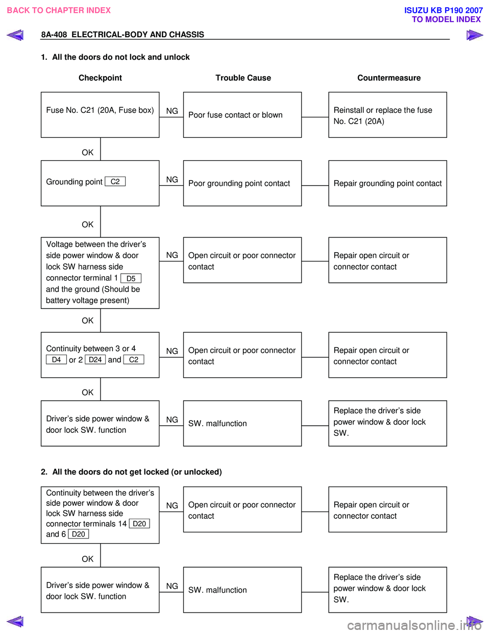
1. All the doors do not lock and unlock
Checkpoint Trouble Cause Countermeasure
Reinstall or replace the fuse
No. C21 (20A)
Poor fuse contact or blown
NG
Repair grounding point contact
Grounding point C2
Poor grounding point contact
Repair open circuit or
connector contact
Voltage between the driver’s
side power window & door
lock SW harness side
connector terminal 1
D5
and the ground (Should be
battery voltage present)
Open circuit or poor connector
contact
NG
NG
OK
OK
OK
Fuse No. C21 (20A, Fuse box)
Repair open circuit or
connector contact
Open circuit or poor connector
contact
NG
Replace the driver’s side
power window & door lock
SW .
Driver’s side power window &
door lock SW . function
SW . malfunction
NG
OK
Continuity between 3 or 4
D4 or 2 D24 and
C2
2. All the doors do not get locked (or unlocked)
Repair open circuit or
connector contact
Open circuit or poor connector
contact
NG
Replace the driver’s side
power window & door lock
SW .
Driver’s side power window &
door lock SW . function
SW . malfunction
NG
OK
Continuity between the driver’s
side power window & door
lock SW harness side
connector terminals 14
D20
and 6
D20
BACK TO CHAPTER INDEX TO MODEL INDEXISUZU KB P190 2007