Page 5483 of 6020

ELECTRICAL-BODY AND CHASSIS 8A-545
Power Door Lock System
General Description
The circuit consists of the door lock (& power window)
switch, door lock actuator for the front and rear door,
tailgate lock actuator and the door lock key switch.
The front door lock switch ‐RH is always provided with
the battery voltage.
The key or the inside lock button on both driver's and
front passenger's door can activate the lock mechanism
of all the doors (including the tailgate).
W hen the driver's door lock switch or the front
passenger's door lock switch is turned on, current flows
for about one second to the door lock actuator of each
door connected in parallel with the front door lock (&
power window) switch ‐LH to activate the actuator to
lock and unlock the doors.
Door Lock Key Switch
Removal and Installation
・ Refer to the Front Door Lock Assembly removal
and installation steps in this section.
Front Door Lock Actuator
Removal and Installation
・ Refer to the Front Door Lock Assembly removal
and installation steps in this section.
Rear Door Lock Actuator
Removal and Installation
・ Refer to the Rear Door Lock Assembly removal
and installation steps in this section.
Tailgate Lock Actuator
Removal and Installation
・ Refer to the Tailgate Lock Assembly removal and
installation steps in this section.
BACK TO CHAPTER INDEX TO MODEL INDEXISUZU KB P190 2007
Page 5485 of 6020
ELECTRICAL-BODY AND CHASSIS 8A-547
Pin-outs
RUW 580SF000301
No. Pin Function
1 Door ajar switch
2 Door ajar indicator light
3 Tailgate switch
4 Test pin (Internal use only)
5 Key switch remote
6 Ignition switch
7 Battery
8 Hazard battery
9 Unlock
10 Lock
11 Front map light
12 Hazard-RH
13 Hazard-LH
14 Ground
BACK TO CHAPTER INDEX TO MODEL INDEXISUZU KB P190 2007
Page 5486 of 6020

8A-548 ELECTRICAL-BODY AND CHASSIS
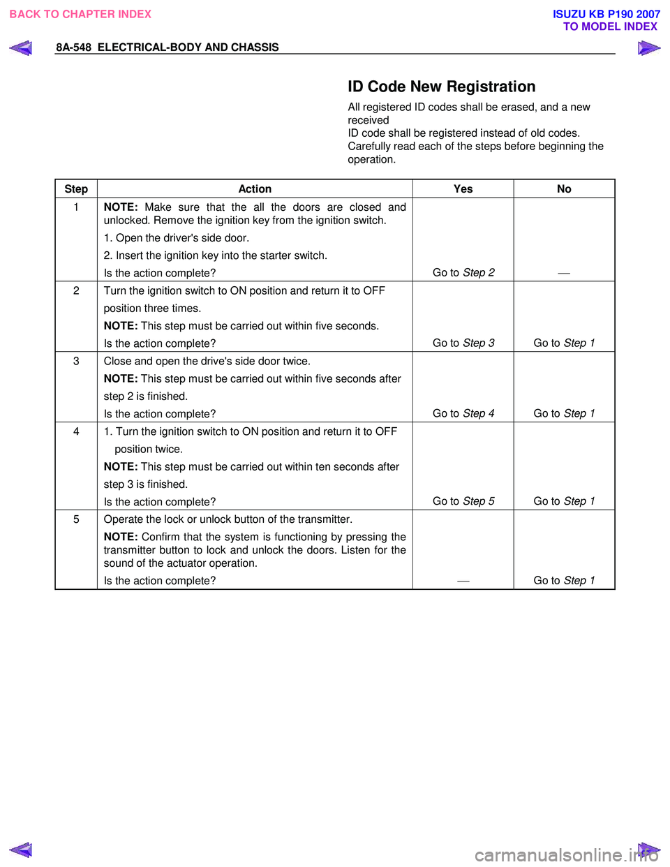
ID Code New Registration
All registered ID codes shall be erased, and a new
received
ID code shall be registered instead of old codes.
Carefully read each of the steps before beginning the
operation.
Step Action Yes No
1 NOTE: Make sure that the all the doors are closed and
unlocked. Remove the ignition key from the ignition switch.
1. Open the driver's side door.
2. Insert the ignition key into the starter switch.
Is the action complete? Go to
Step 2
2 Turn the ignition switch to ON position and return it to OFF
position three times.
NOTE: This step must be carried out within five seconds.
Is the action complete? Go to
Step 3 Go to Step 1
3 Close and open the drive's side door twice.
NOTE: This step must be carried out within five seconds after
step 2 is finished.
Is the action complete? Go to
Step 4 Go to Step 1
4 1. Turn the ignition switch to ON position and return it to OFF
position twice.
NOTE: This step must be carried out within ten seconds after
step 3 is finished.
Is the action complete? Go to
Step 5 Go to Step 1
5 Operate the lock or unlock button of the transmitter.
NOTE: Confirm that the system is functioning by pressing the
transmitter button to lock and unlock the doors. Listen for the
sound of the actuator operation.
Is the action complete?
Go to Step 1
BACK TO CHAPTER INDEX TO MODEL INDEXISUZU KB P190 2007
Page 5488 of 6020

8A-550 ELECTRICAL-BODY AND CHASSIS
ID Code Additional Registration
A new received ID code shall be additionally registered
with holding registered ID codes. W hen a total of
already registered and newly
registered ID code exceeds 4, the oldest one shall be
erased.
Step Action Yes No
1 NOTE: Make sure that the all the doors are closed and
unlocked. Remove the ignition key from the ignition switch.
1. Open the driver's side door.
2. Insert the ignition key into the starter switch.
Is the action complete? Go to
Step 2
2 Turn the ignition switch to ON position and return it to OFF
position three times.
NOTE: This step must be carried out within five seconds .
Is the action complete? Go to
Step 3 Go to Step 1
3 Close and open the driver's side door once.
NOTE: This step must be carried out within five seconds after
step 2 is finished.
Is the action complete? Go to
Step 4 Go to Step 1
4 1. Turn the ignition switch to ON position and return it to OFF
position once.
Check that the hazard lamp blinks 3 times.
NOTE: This step must be carried out within ten seconds after
step 3 is finished.
Is the action complete? Go to
Step 5 Go to Step 1
5 Operate the lock or unlock button of the transmitter.
NOTE: Confirm that the system is functioning by pressing the
transmitter button to lock and unlock the doors. Listen for the
sound of the actuator operation.
Is the action complete?
Go to Step 1
BACK TO CHAPTER INDEX
TO MODEL INDEXISUZU KB P190 2007
Page 5490 of 6020
8A-552 ELECTRICAL-BODY AND CHASSIS
ID Code Check
Numbers of registered ID code shall be checked in this
mode.
Step Action Yes No
1 NOTE: Make sure that the all the doors are closed.
Is the action complete? Go to Step 2
2 Insert the ignition key into the key lock twice, and then re-
inserted.
NOTE: This step must be carried out within five seconds.
Count the number of times the hazard lights flash on and off.
This number is equal to the number of registrations.
Is the action complete? Go to Step 1 Go to Step 1
RUW 59DLF000101
BACK TO CHAPTER INDEX TO MODEL INDEXISUZU KB P190 2007
Page 5522 of 6020
8A-584 ELECTRICAL-BODY AND CHASSIS
RTW 38DLH000101
Menu
The left table shows witch functions are used for the
available equipment versions.
NOTE: Marked items are not applied for keyless entry
system.
DTC
On OBD has three options available in the Tech-2
DTC mode to display the enhanced information
available.
• Read DTC Info Ordered By Priority.
• Read DTC Info As Stored By ECU.
• Clear DTC and Alarm Code Info.
Clear DTC Information
To clear Diagnostic Trouble Codes (DTCs), Use the
diagnostic scan tool “Clear DTC Information” function.
Tech-2 Data Display
The Tech-2 data values represent values that would
be seen on a normally-keyless entry system.
RTW 38DSH001601
Actuator Test
Unlock/Lock Test
Check whether opening and closing of a door lock
can be performed by operation of Tech-2.
1. Turn the key “OFF”.
2. Turn the key “ON”.
3. Check the display and test menu.
4. Operate the Tech-2.
BACK TO CHAPTER INDEX TO MODEL INDEXISUZU KB P190 2007
Page 5546 of 6020
8A-608 ELECTRICAL-BODY AND CHASSIS
No. Connector face No. Connector face
B53
White
J/B I1 B63
WhiteIgnition switch (IGSUB: G2)
B54
White
J/B I2 B64
W eld splice 1 (Illumination)
B55
White
J/B I3 B65
W eld splice 2 (Ground)
B56
White
J/B I4 B66
White4W D switch
B57
White
HVAC control unit B67
WhiteCruise main switch
B58
Black
Data link connector B68
WhiteImmobilizer
B59
White
Combination switch-A B69
Gray Door lock switch
B60
Black
Combination switch-B B70
~
B71 NOT USED
B61
Black
Flasher unit B72
YellowInflator module passenger
B62
White
Ignition switch (IGSUB: G1) B73
W eld Splice 3
BACK TO CHAPTER INDEX TO MODEL INDEXISUZU KB P190 2007
Page 5547 of 6020
ELECTRICAL-BODY AND CHASSIS 8A-609
No. Connector face No. Connector face
B74
NOT USED B85
W eld splice 7 (Ground)
B75
Black
Rear fog light C/U B86
W eld splice 8 (Ground)
B76
White
Front rear fog light switch B87
NOT USED
B77
White
Immobilizer C/U B88
W eld splice 5 (Ground)
B78
White
Key cylinder antenna coil B89
~
B94 NOT USED
B79
White
Short connector (cooler only) B95
White
Keyless entry control unit
B80
Black
Hazard relay (RH) B96
Gray PIM1
B81
Black
Hazard relay (LH) B97
WhitePIM2
B82
W eld splice 6 (Ground) B98
WhiteDoor lock C/U
B83
~
B84 NOT USED B101
White
Key inter lock
BACK TO CHAPTER INDEX TO MODEL INDEXISUZU KB P190 2007