2007 ISUZU KB P190 door lock
[x] Cancel search: door lockPage 5778 of 6020
10-20 CAB
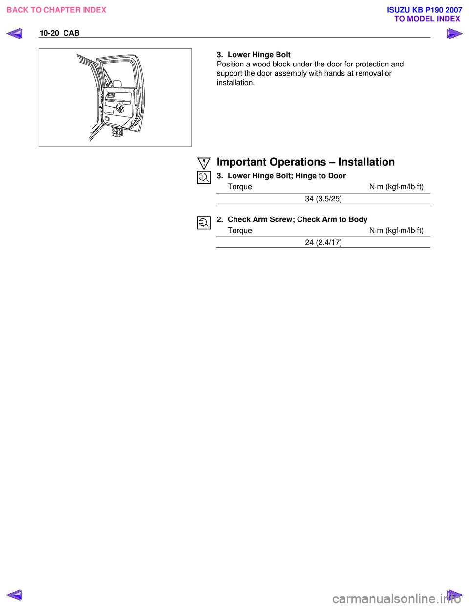
3. Lower Hinge Bolt
Position a wood block under the door for protection and
support the door assembly with hands at removal or
installation.
Important Operations – Installation
3. Lower Hinge Bolt; Hinge to Door
Torque N ⋅m (kgf ⋅m/lb ⋅ft)
34 (3.5/25)
2. Check Arm Screw; Check Arm to Body
Torque N ⋅m (kgf ⋅m/lb ⋅ft)
24 (2.4/17)
BACK TO CHAPTER INDEX TO MODEL INDEX
ISUZU KB P190 2007
Page 5779 of 6020
CAB 10-21
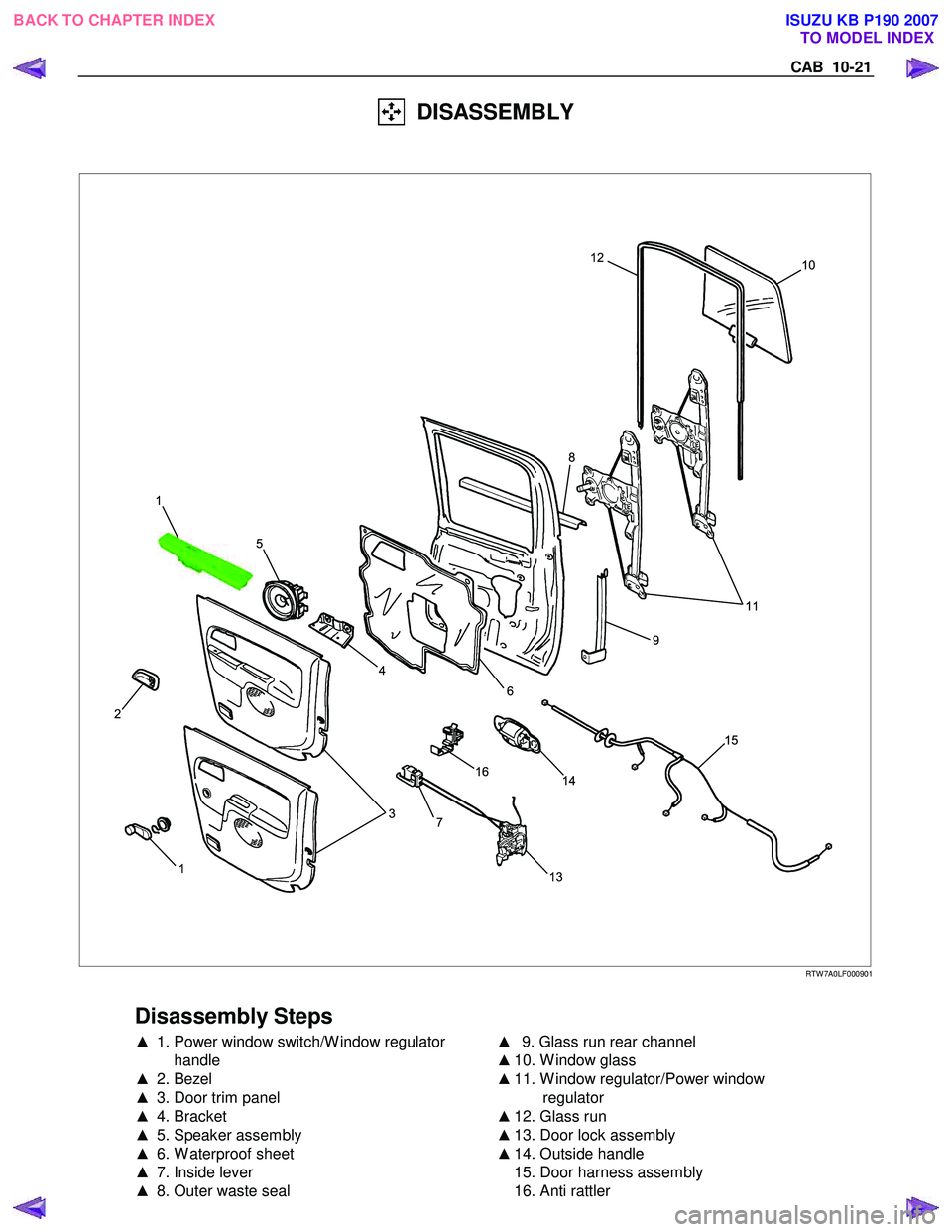
DISASSEMBLY
10
11
15
14
16
7
13
3
4
5
1
2
9
6 8
12
1
RTW 7A0LF000901
Disassembly Steps
▲
1. Power window switch/W indow regulator
handle
▲ 2. Bezel
▲ 3. Door trim panel
▲ 4. Bracket
▲ 5. Speaker assembly
▲ 6. W aterproof sheet
▲ 7. Inside lever
▲ 8. Outer waste seal
▲
9. Glass run rear channel
▲ 10. W indow glass
▲ 11. W indow regulator/Power window
regulator
▲ 12. Glass run
▲ 13. Door lock assembly
▲ 14. Outside handle
15. Door harness assembly
16. Anti rattler
BACK TO CHAPTER INDEX
TO MODEL INDEX
ISUZU KB P190 2007
Page 5781 of 6020
CAB 10-23
4. Bracket
5. Speaker assembly • Remove the fixing bolt and then remove the connector.
6. Waterproof Sheet • Take care not to damage the sheet when peeling it off.
7. Inside Lever • Disconnect the door lock cables.
8. Outer Waste Seal
9. Glass Run Rear Channel • Remove the bolt.
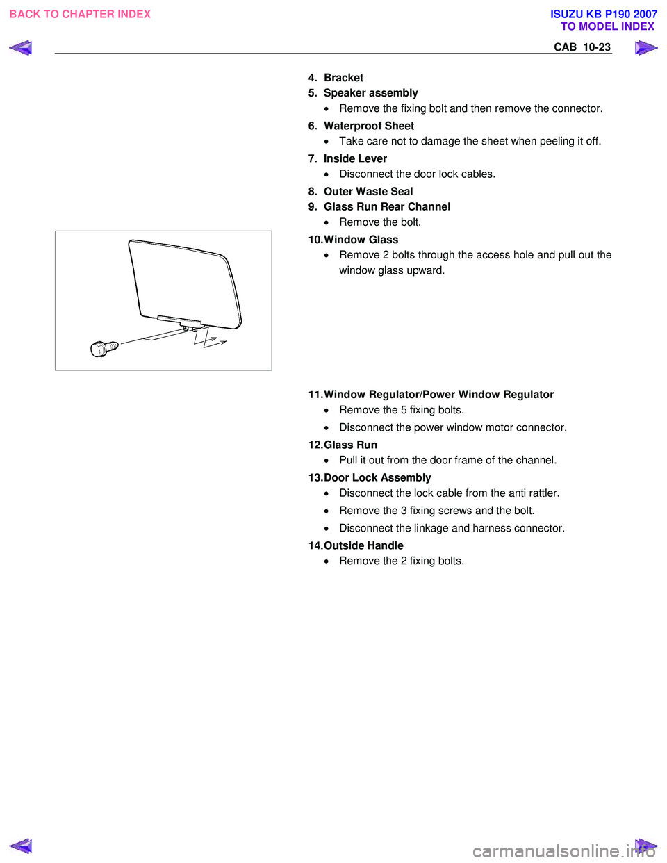
10. Window Glass
• Remove 2 bolts through the access hole and pull out the
window glass upward.
11. Window Regulator/Power Window Regulator
• Remove the 5 fixing bolts.
• Disconnect the power window motor connector.
12. Glass Run • Pull it out from the door frame of the channel.
13. Door Lock Assembly • Disconnect the lock cable from the anti rattler.
• Remove the 3 fixing screws and the bolt.
• Disconnect the linkage and harness connector.
14. Outside Handle • Remove the 2 fixing bolts.
BACK TO CHAPTER INDEX
TO MODEL INDEX
ISUZU KB P190 2007
Page 5782 of 6020
10-24 CAB
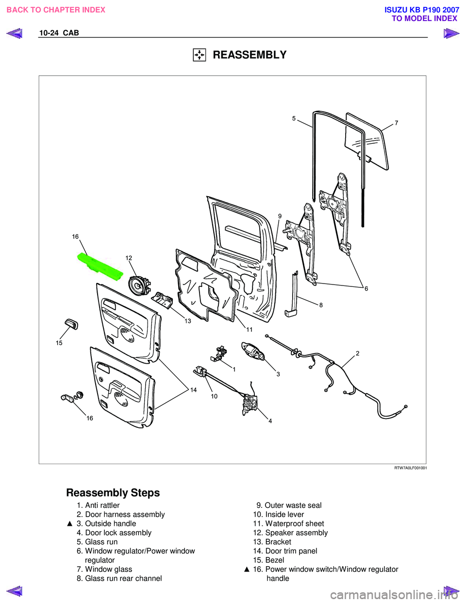
REASSEMBLY
7
6
2
3
1
10 4
14
13
11
12
16
15
8
9 5
16
RTW 7A0LF001001
Reassembly Steps
1. Anti rattler
2. Door harness assembly
▲ 3. Outside handle
4. Door lock assembly
5. Glass run
6. W indow regulator/Power window regulator
7. W indow glass
8. Glass run rear channel
9. Outer waste seal
10. Inside lever
11. W aterproof sheet
12. Speaker assembly
13. Bracket
14. Door trim panel
15. Bezel
▲ 16. Power window switch/W indow regulator
handle
BACK TO CHAPTER INDEX TO MODEL INDEX
ISUZU KB P190 2007
Page 5896 of 6020
IMMOBILIZER CONTROL SYSTEM (4JK1/4JJ1/HFV6) 11A-45
Description and Operation
Immobilizer System Description
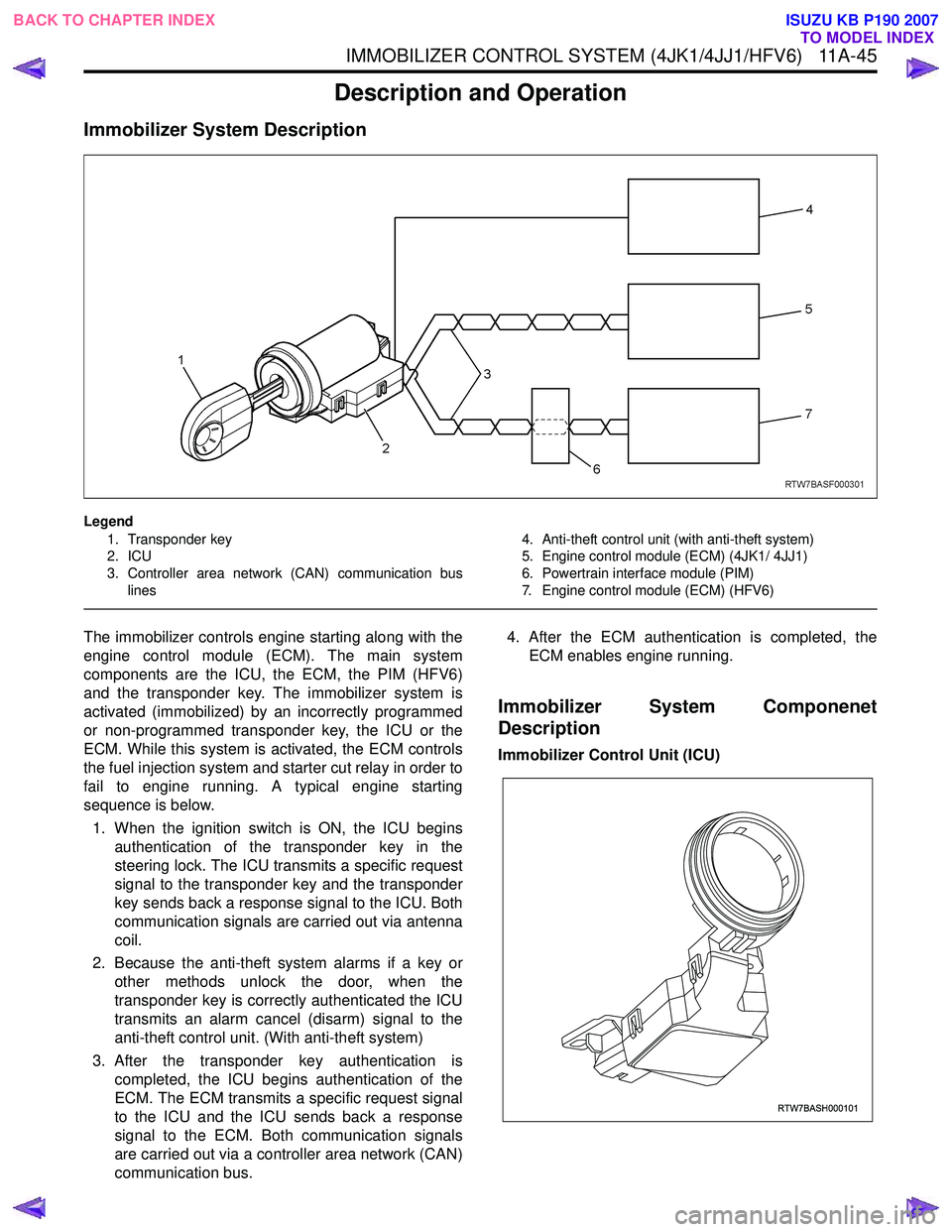
Legend1. Transponder key
2. ICU
3. Controller area network (CAN) communication bus lines 4. Anti-theft control unit (with anti-theft system)
5. Engine control module (ECM) (4JK1/ 4JJ1)
6. Powertrain interface module (PIM)
7. Engine control module (ECM) (HFV6)
The immobilizer controls engine starting along with the
engine control module (ECM). The main system
components are the ICU, the ECM, the PIM (HFV6)
and the transponder key. The immobilizer system is
activated (immobilized) by an incorrectly programmed
or non-programmed transponder key, the ICU or the
ECM. While this system is activated, the ECM controls
the fuel injection system and starter cut relay in order to
fail to engine running. A typical engine starting
sequence is below.
1. When the ignition switch is ON, the ICU begins authentication of the transponder key in the
steering lock. The ICU transmits a specific request
signal to the transponder key and the transponder
key sends back a response signal to the ICU. Both
communication signals are carried out via antenna
coil.
2. Because the anti-theft system alarms if a key or other methods unlock the door, when the
transponder key is correctly authenticated the ICU
transmits an alarm cancel (disarm) signal to the
anti-theft control unit. (With anti-theft system)
3. After the transponder key authentication is completed, the ICU begins authentication of the
ECM. The ECM transmits a specific request signal
to the ICU and the ICU sends back a response
signal to the ECM. Both communication signals
are carried out via a controller area network (CAN)
communication bus. 4. After the ECM authentication is completed, the
ECM enables engine running.
Immobilizer System Componenet
Description
Immobilizer Control Unit (ICU)
RTW7BASH000101
BACK TO CHAPTER INDEX TO MODEL INDEX
ISUZU KB P190 2007
Page 5955 of 6020
ANTITHEFT SYSTEM 11B-1
SECTION 11B
ANTITHEFT SYSTEM
TABLE OF CONTENTS
Service Precaution .................................................. 11B- 2
General Description ................................................ 11B- 2
Diagrams And Schematics ................................. 11B- 5 System W iring Diagrams ................................ 11B- 5
Parts Location ................................................. 11B- 6
Circuit Diagram ..............................................11B-10
Antitheft control unit (A) ...................................11B-24
Pin-outs ...........................................................11B-24
Pin-Assignment ...............................................11B-25
lmportant information on Programming..............11B-26
Tech-2 Scan Tool ...............................................11B-27 Operating Procedure .......................................11B-27
Menu ...............................................................11B-28
DTC .................................................................11B-28
Clear DTC Information ....................................11B-28
Tech-2 Data Display........................................11B-28
Actuator Test ...................................................11B-28
Programming...................................................11B-30
Tech-2 Data List ..............................................11B-35
Diagnosis............................................................11B-36 Diagnostic procedure ......................................11B-36
Clearing Diagnostic Trouble Codes ................11B-36
Verifying Vehicle Repair ..................................11B-36
Diagnostic Aids................................................11B-36
Diagnostic Trouble Code (DTC) list
For Antitheft.....................................................11B-37
Antitheft System Check ...................................11B-38
No Antitheft Lamp ...........................................11B-39
DTC13 Security code not yet programmed .....11B-40
DTC14 No remote key programmed ...............11B-41
DTC16 Door lock actuators short circuit
to ground .........................................................11B-42
DTC20 Broken wire to door lock actuators .....11B-43
DTC21 Remote key 1 with random code
out of capture range ........................................11B-44
DTC22 Remote key 2 with random code
out of capture range ........................................11B-45
DTC23 Remote key 3 with random code
out of capture range ........................................11B-46
DTC24 Remote key 4 with random code
out of capture range ........................................ 11B-47
DTC25 Remote key 5 with random code
out of capture range ........................................ 11B-48
DTC28 Input immobilizer short circuit
to ground ......................................................... 11B-49
DTC29 Broken wire to immobilizer ................. 11B-50
DTC31 Actuator driver door defect ................. 11B-51
DTC32 Actuator passenger door defect ......... 11B-52
DTC36 Broken wire to driver door................... 11B-53
DTC37 Broken wire to passenger door........... 11B-54
DTC41 Driver door Lock switch unlock
defect .............................................................. 11B-55
DTC42 Driver door Lock switch lock defect .... 11B-56
DTC43 Driver door Lock switch Super lock
defect .............................................................. 11B-57
DTC44 Passenger door Lock switch lock
defect .............................................................. 11B-58
DTC45 Passenger door Lock switch unlock
defect .............................................................. 11B-59
DTC47 Battery voltage for door lock actuators
is missing ........................................................ 11B-60
DTC50 A/D converter defect or battery
voltage less than 9 volt.................................... 11B-61
DTC51 EEPROM defect ................................. 11B-62
DTC52 EEPROM not programmed
by ISUZU ......................................................... 11B-63
DTC55 Control unit defect............................... 11B-64
DTC123 Output flasher short circuit to ground
or broken wire ................................................. 11B-65
DTC125 Output alarm horn broken wire ......... 11B-66
BACK TO CHAPTER INDEX TO MODEL INDEX
ISUZU KB P190 2007
Page 5956 of 6020
11B-2 ANTITHEFT SYSTEM
Service Precaution
WARNING: THIS VEHICLE HAS A SUPPLEMENTAL
RESTRAINT SYSTEM (SRS). REFER TO THE SRS
COMPONENT AND WIRING LOCATION VIEW IN
ORDER TO DETERMINE WHETHER YOU ARE
PERFORMING SERVICE ON OR NEAR THE SRS
COMPONENTS OR THE SRS WIRING. WHEN YOU
ARE PERFORMING SERVICE ON OR NEAR THE
SRS COMPONENTS OR THE SRS WIRING, REFER
TO THE SRS SERVICE INFORMATION. FAILURE TO
FOLLOW WARNINGS COULD RESULT IN
POSSIBLE AIR BAG DEPLOYMENT, PERSONAL
INJURY, OR OTHERWISE UNNEEDED SRS SYSTEM
REPAIRS.
CAUTION: Always use the correct fastener in the
proper location. When you replace a fastener, use
ONLY the exact part number for that application.
ISUZU will call out those fasteners that require a
replacement after removal. ISUZU will also call out
the fasteners that require thread lockers or thread
sealant. UNLESS OTHERWISE SPECIFIED, do not
use supplemental coatings (Paints, greases, or
other corrosion inhibitors) on threaded fasteners or
fastener joint interfaces. Generally, such coatings
adversely affect the fastener torque and the joint
clamping force, and may damage the fastener.
When you install fasteners, use the correct
tightening sequence and specifications. Following
these instructions can help you avoid damage to
parts and systems.
General Description
The Antitheft system consists of the four major
components which are Antitheft Control Unit (ACU),
Antitheft horn, key (remote key), and scan tool (Tech-2).
This system can be activated by a correctly
programmed key (remote key) and starter switch is set
to OFF.
This system can be deactivated by a correctly
programmed key (remote key) connected with a
correctly programmed ACU and a correctly
programmed lCU.
W hen the vehicle doors, and engine hood are locked,
the antitheft alarm system is designed to protect your
vehicle and valuables from theft.
Any attempt to forcibly open any door, the engine hood
without using the vehicle key (or remote control) will
cause the hazard lights to flash on and off and the horn
to sound intermittently. This will continue for 30 seconds
(Hazard lamp flash; For 5 minutes) before the system
automatically shuts itself off.
Please operate the door either the key lock or remote
key after closing all doors to arm the alarm system.
Miss waning will be detected when the passenger door
is opened with locked condition and then this door is
closed.
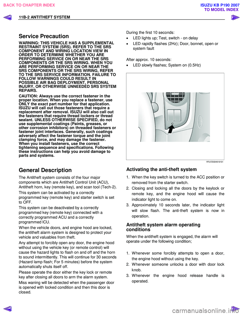
During the first 10 seconds:
• LED lights up; Test, switch - on delay
• LED rapidly flashes (2Hz); Door, bonnet, open or
system fault
After approx. 10 seconds:
• LED slowly flashes; System on (0.5Hz)
RTU7Z0SH019101
Activating the anti-theft system
1. W hen the key switch is turned to the ACC position or
removed from the starter switch.
2. Closing and locking all the doors by the keylock o
r
remote key, and the engine hood will cause the
indicator light to come on.
3. Approximately 10 seconds later, the indicator light will slow flash. The anti-theft system is now in
operation.
Antitheft system alarm operating
conditions
W hen the antitheft system is engaged, the alarm will
operate under the following condition;
1. W henever some forcibly attempts to open a door, the engine hood without using the key.
2. W henever someone unlocks a door with door lock knob.
3. W henever the engine hood release handle is operated.
BACK TO CHAPTER INDEX TO MODEL INDEX
ISUZU KB P190 2007
Page 5957 of 6020
ANTITHEFT SYSTEM 11B-3
Function of a keyless entry system
W ith a keyless entry system the car can be locked or
unlocked from any position around the car up to a
specified distance, by using the potable radio remote
transmitter inside key (remote key).
Status LED
W hile the system is in delay the alarm system is active
and LED flashes at 0.5Hz with or without activated
interior protection.
Hazard relay
The hazard warning lights will be activated by an
external relay. The output is low active.
Switches
All switches to ground. This makes it possible for failure
analysis to detect a short circuit or a broken wire to
each switch. To use this feature it is necessary to place
a 1.8k Ω resistor in parallel to the required switch.
Receiver
The receiver is integrated into the control unit.
To lower the idle current the receiver is equipped with a
standby mode. The antenna is integrated on the printed
circuit board.
Depending on the mounting position of the control unit
the antenna can be connected externally.
Range of communication
The range of communication between remote key and
receiver is intended to be least 3 m from centre of the
car.
Diagnosis
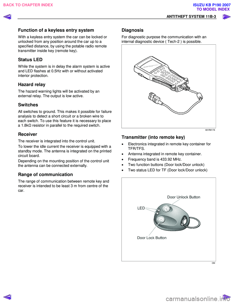
For diagnostic purpose the communication with an
internal diagnostic device ( Tech-2 ) is possible.
901RW 176
Transmitter (into remote key)
• Electronics integrated in remote key container for
TFR/TFS.
• Antenna integrated in remote key container.
• Frequency band is 433.92 MHz.
• Two function buttons (Door lock/Door unlock)
• Two status LED for TF (Door lock/Door unlock)
OM
BACK TO CHAPTER INDEX TO MODEL INDEX
ISUZU KB P190 2007