Page 5368 of 6020

8A-430 ELECTRICAL-BODY AND CHASSIS
REMOVAL AND INSTALLATION
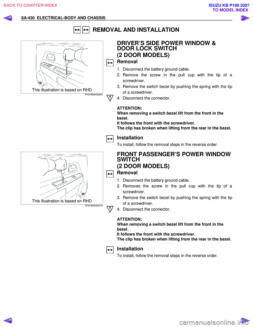
This illustration is based on RHD RTW 780SH002601
DRIVER’S SIDE POWER WINDOW &
DOOR LOCK SWITCH
(2 DOOR MODELS)
Removal
1. Disconnect the battery ground cable.
2. Remove the screw in the pull cup with the tip of a screwdriver.
3. Remove the switch bezel by pushing the spring with the tip of a screwdriver.
4. Disconnect the connector.
ATTENTION:
When removing a switch bezel lift from the front in the
bezel.
It follows the front with the screwdriver.
The clip has broken when lifting from the rear in the bezel.
Installation
To install, follow the removal steps in the reverse order.
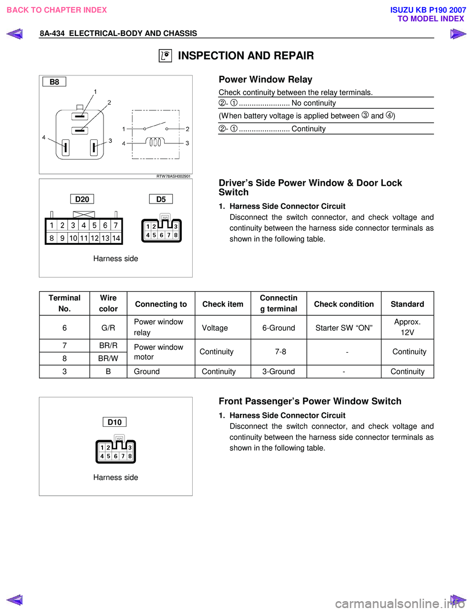
This illustration is based on RHD RTW 780SH002701
FRONT PASSENGER’S POWER WINDOW
SWITCH
(2 DOOR MODELS)
Removal
1. Disconnect the battery ground cable.
2. Removes the screw in the pull cup with the tip of a screwdriver.
3. Remove the switch bezel by pushing the spring with the tip of a screwdriver.
4. Disconnect the connector.
ATTENTION:
When removing a switch bezel lift from the front in the
bezel.
It follows the front with the screwdriver.
The clip has broken when lifting from the rear in the bezel.
Installation
To install, follow the removal steps in the reverse order.
BACK TO CHAPTER INDEX TO MODEL INDEXISUZU KB P190 2007
Page 5369 of 6020

ELECTRICAL-BODY AND CHASSIS 8A-431
This illustration is based on RHD RTW 780SH002601
DRIVER’S SIDE POWER WINDOW &
DOOR LOCK SWITCH
(4 DOOR MODELS)
Removal
1. Disconnect the battery ground cable.
2. Removes the screw in pull cup with the tip of a screwdriver.
3. Remove the switch bezel by pushing the spring with the tip of a screwdriver.
4. Disconnect the connector.
ATTENTION:
When removing a switch bezel lift from the front in the
bezel.
It follows the front with the screwdriver.
The clip has broken when lifting from the rear in the bezel.
Installation
To install, follow the removal steps in the reverse order.
This illustration is based on RHD RTW 780SH002701
FRONT PASSENGER’S POWER WINDOW
SWITCH
(4 DOOR MODELS)
Removal
1. Disconnect the battery ground cable.
2. Removes the screw in pull cup with the tip of a screwdriver.
3. Remove the switch bezel by pushing the spring with the tip of a screwdriver.
4. Disconnect the connector.
ATTENTION:
When removing a switch bezel lift from the front in the
bezel.
It follows the front with the screwdriver.
The clip has broken when lifting from the rear in the bezel.
Installation
To install, follow the removal steps in the reverse order.
BACK TO CHAPTER INDEX TO MODEL INDEXISUZU KB P190 2007
Page 5370 of 6020
8A-432 ELECTRICAL-BODY AND CHASSIS
RTW 780SH002801
REAR POWER WINDOW & DOOR LOCK
SWITCH-LH & RH
Removal
1. Disconnect the battery ground cable.
2. Remove the screw in the pull cup with the tip of a screwdriver.
3. Remove the switch bezel by pushing the spring with the tip of a screwdriver.
4. Disconnect the connector.
ATTENTION:
When removing a switch bezel lift from the front in the
bezel.
It follows the front with the screwdriver.
The clip has broken when lifting from the rear in the bezel.
Installation
To install, follow the removal steps in the reverse order.
BACK TO CHAPTER INDEX TO MODEL INDEXISUZU KB P190 2007
Page 5372 of 6020

8A-434 ELECTRICAL-BODY AND CHASSIS
INSPECTION AND REPAIR
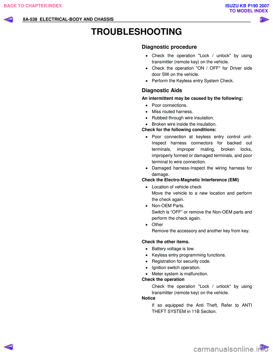
B8
RTW 78ASH002901
Power Window Relay
Check continuity between the relay terminals.
2- 1........................ No continuity
(W hen battery voltage is applied between
3 and 4)
2- 1........................ Continuity
Harness side
D20 D5
Driver’s Side Power Window & Door Lock
Switch
1. Harness Side Connector Circuit
Disconnect the switch connector, and check voltage and continuity between the harness side connector terminals as
shown in the following table.
Terminal No. Wire
color Connecting to Check item Connectin
g terminal Check condition Standard
6 G/R Power window
relay Voltage 6-Ground Starter SW “ON” Approx.
12V
7 BR/R Power window
8 BR/W motor
3 B Ground Continuity 3-Ground - Continuity
Harness side
D10
Front Passenger’s Power Window Switch
1. Harness Side Connector Circuit
Disconnect the switch connector, and check voltage and continuity between the harness side connector terminals as
shown in the following table.
Continuity
-
7-8
Continuity
BACK TO CHAPTER INDEX
TO MODEL INDEXISUZU KB P190 2007
Page 5374 of 6020
8A-436 ELECTRICAL-BODY AND CHASSIS
Harness side
D5
Driver’s Side Power Window Motor
1. Driver’s Side Power Window & Door Lock Switch
Connector Circuit
Disconnect the switch connector, apply the battery voltage (12V) to the harness side connector terminals and check
operation.
Connecting terminals Operation
7 (BR/R) 8 (BR/W ) direction
- + DOW N
+ - UP
D1
2. Driver’s Side Power Window Motor Connector Circuit
Disconnect the switch connector, apply the battery voltage (12V) to the motor side connector terminals and check
operation.
Connecting terminals Operation
1 2 direction
+ - DOW N
- + UP
BACK TO CHAPTER INDEX
TO MODEL INDEXISUZU KB P190 2007
Page 5476 of 6020

8A-538 ELECTRICAL-BODY AND CHASSIS
TROUBLESHOOTING
Diagnostic procedure
•
Check the operation "Lock / unlock" by using
transmitter (remote key) on the vehicle.
• Check the operation "ON / OFF" for Driver side
door SW on the vehicle.
• Perform the Keyless entry System Check.
Diagnostic Aids
An intermittent may be caused by the following:
• Poor connections.
• Miss routed harness.
• Rubbed through wire insulation.
• Broken wire inside the insulation.
Check for the following conditions:
• Poor connection at keyless entry control unit-
Inspect harness connectors for backed out
terminals, improper mating, broken locks,
improperly formed or damaged terminals, and poo
r
terminal to wire connection.
• Damaged harness-Inspect the wiring harness fo
r
damage.
Check the Electro-Magnetic Interference (EMI)
• Location of vehicle check
Move the vehicle to a new location and perform
the check again.
• Non-OEM Parts.
Switch is “OFF” or remove the Non-OEM parts and
perform the check again.
• Other
Remove the accessory and another key from key.
Check the other items.
• Battery voltage is low.
• Keyless entry programming functions.
• Registration for security code.
• Ignition switch operation.
• Meter system is malfunction.
Check the operation
Check the operation "Lock / unlock" by using
transmitter (remote key) on the vehicle.
Notice
If so equipped the Anti Theft, Refer to ANTI
THEFT SYSTEM in 11B Section.
BACK TO CHAPTER INDEX TO MODEL INDEXISUZU KB P190 2007
Page 5479 of 6020

ELECTRICAL-BODY AND CHASSIS 8A-541
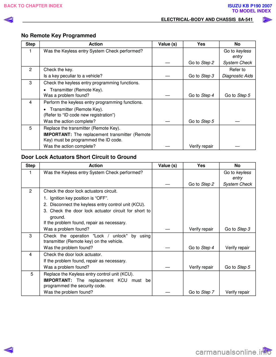
No Remote Key Programmed
Step Action Value (s) Yes No
1 W as the Keyless entry System Check performed?
— Go to Step 2 Go to
keyless
entry
System Check
2 Check the key. Is a key peculiar to a vehicle? — Go to Step 3 Refer to
Diagnostic Aids
3 Check the keyless entry programming functions.
• Transmitter (Remote Key).
W as a problem found? — Go to Step 4 Go to Step 5
4 Perform the keyless entry programming functions.
• Transmitter (Remote Key).
(Refer to “ID code new registration”)
W as the action complete? — Go to Step 5 —
5 Replace the transmitter (Remote Key).
IMPORTANT: The replacement transmitter (Remote
Key) must be programmed the ID code.
W as the action complete? — Verify repair —
Door Lock Actuators Short Circuit to Ground
Step Action Value (s) Yes No
1 W as the Keyless entry System Check performed?
— Go to Step 2 Go to
keyless
entry
System Check
2 Check the door lock actuators circuit.
1. Ignition key position is “OFF”.
2. Disconnect the keyless entry control unit (KCU).
3. Check the door lock actuator circuit for short to ground.
If the problem found, repair as necessary.
W as a problem found? — Verify repair Go to Step 3
3 Check the operation "Lock / unlock" by using
transmitter (Remote key) on the vehicle.
W as the problem found? — Go to Step 4 Verify repair
4 Check the door lock actuator.
If the problem found, repair as necessary.
W as a problem found? — Verify repair Go to Step 5
5 Replace the Keyless entry control unit (KCU).
IMPORTANT: The replacement KCU must be
programmed the security code.
W as the problem found? — Go to Step 7 Verify repair
BACK TO CHAPTER INDEX
TO MODEL INDEXISUZU KB P190 2007
Page 5482 of 6020
8A-544 ELECTRICAL-BODY AND CHASSIS
Keyless Entry System
General Description
The system’s main features are summarized as follows.
・ Keyless entry with visual feedback
・ Highly secure encrypted transmission format
incorporating rolling code strategy
・ Field programmable remote keys
・ Door lock control
・ Illuminated entry with fade out
・ Illuminated exit
・ Remote door lock / ignition key interlock
・ Door ajar warning indicator in the cluster
BACK TO CHAPTER INDEX
TO MODEL INDEXISUZU KB P190 2007