2007 ISUZU KB P190 power steering
[x] Cancel search: power steeringPage 5672 of 6020
SUPPLEMENTAL RESTRAINT SYSTEM 9A-37
Driver Air Bag Assembly
Service Precautions
WARNING: SAFETY PRECAUTIONS MUST BE
FOLLOWED WHEN HANDLING A DEPLOYED AIR
BAG ASSEMBLY. AFTER DEPLOYMENT, THE AIR
BAG ASSEMBLY SURFACE MAY CONTAIN
A
SMALL AMOUNT OF SODIUM HYDROXIDE, A BY–
PRODUCT OF THE DEPLOYMENT REACTION
THAT IS IRRITATING TO THE SKIN AND EYES.
MOST OF THE POWDER ON THE AIR BAG
ASSEMBLY IS HARMLESS. AS A PRECAUTION,
WEAR GLOVES AND SAFETY GLASSES WHEN
HANDLING A DEPLOYED AIR BAG ASSEMBLY,
AND WASH YOUR HANDS WITH MILD SOAP AND
WATER AFTERWARDS.
WARNING: WHEN CARRYING A LIVE AIR BAG
ASSEMBLY, MAKE SURE THE BAG AND TRIM
COVER ARE POINTED AWAY FROM YOU. NEVER
CARRY THE AIR BAG ASSEMBLY BY THE WIRES
OR CONNECTOR ON THE UNDERSIDE OF THE
MODULE. IN THE CASE OF AN ACCIDENTAL
DEPLOYMENT, THE BAG WILL THEN DEPLOY
WITH MINIMAL CHANCE OF INJURY. WHEN
PLACING ALIVE AIR BAG ASSEMBLY ON
A
BENCH OR OTHER SURFACE, ALWAYS FACE
THE BAG AND TRIM COVER UP, AWAY FROM THE
SURFACE. NEVER REST A STEERING COLUMN
ASSEMBLY ON THE STEERING WHEEL WITH THE
AIR BAG ASSEMBLY FACE DOWN AND COLUMN
VERTICAL. THIS IS NECESSARY SO THAT A FREE
SPACE IS PROVIDED TO ALLOW THE AIR BAG
ASSEMBLY TO EXPAND IN THE UNLIKELY EVENT
OF ACCIDENTAL DEPLOYMENT. OTHERWISE,
PERSONAL INJURY COULD RESULT.
NOTE: In the event deployment has occurred, inspect
the coil assembly wire for any signs of scorching,
melting or any other damage due to excessive heat. I
f
the coil has been damaged, replace it.
Removal
Refer to the “Inflator Module” in the “Power-Assisted
Steering System” section.
Installation
Refer to the “Inflator Module” in the “Power-Assisted
Steering System” section.
BACK TO CHAPTER INDEX
TO MODEL INDEXISUZU KB P190 2007
Page 5673 of 6020
9A-38 SUPPLEMENTAL RESTRAINT SYSTEM
Steering Wheel
Service Precautions
WARNING: SAFETY PRECAUTIONS MUST BE
FOLLOWED WHEN HANDLING A DEPLOYED AIR
BAG ASSEMBLY. AFTER DEPLOYMENT, THE AIR
BAG ASSEMBLY SURFACE MAY CONTAIN
A
SMALL AMOUNT OF SODIUM HYDROXIDE, A BY–
PRODUCT OF THE DEPLOYMENT REACTION
THAT IS IRRITATING TO THE SKIN AND EYES.
MOST OF THE POWDER ON THE AIR BAG
ASSEMBLY IS HARMLESS. AS A PRECAUTION,
WEAR GLOVES AND SAFETY GLASSES WHEN
HANDLING A DEPLOYED AIR BAG ASSEMBLY,
AND WASH YOUR HANDS WITH MILD SOAP AND
WATER AFTERWARDS.
WARNING: WHEN CARRYING A LIVE AIR BAG
ASSEMBLY, MAKE SURE THE BAG AND TRIM
COVER ARE POINTED AWAY FROM YOU. NEVER
CARRY AN AIR BAG ASSEMBLY BY THE WIRES
OR CONNECTOR ON THE UNDERSIDE OF THE
MODULE. IN THE CASE OF AN ACCIDENTAL
DEPLOYMENT, THE BAG WILL THEN DEPLOY
WITH MINIMAL CHANCE OF INJURY. WHEN
PLACING ALIVE AIR BAG ASSEMBLY ON
A
BENCH OR OTHER SURFACE, ALWAYS FACE
THE BAG AND TRIM COVER UP, AWAY FROM THE
SURFACE. NEVER REST A STEERING COLUMN
ASSEMBLY ON THE STEERING WHEEL WITH THE
AIR BAG ASSEMBLY FACE DOWN AND COLUMN
VERTICAL. THIS IS NECESSARY SO THAT A FREE
SPACE IS PROVIDED TO ALLOW THE AIR BAG
ASSEMBLY TO EXPAND IN THE UNLIKELY EVENT
OF ACCIDENTAL DEPLOYMENT. OTHERWISE,
PERSONAL INJURY COULD RESULT.
In the event deployment has occurred, inspect the coil
assembly wire for any signs of scorching, melting o
r
any other damage due to excessive heat. If the coil
has been damaged, replace it.
Removal
Refer to the “Steering W heel” in the “Power-Assisted
Steering System” section.
Installation
Refer to the “Steering W heel” in the “Power-Assisted
Steering W heel” section.
BACK TO CHAPTER INDEX
TO MODEL INDEXISUZU KB P190 2007
Page 5674 of 6020
SUPPLEMENTAL RESTRAINT SYSTEM 9A-39
SRS Coil Assembly
Service Precautions
WARNING: SAFETY PRECAUTIONS MUST BE
FOLLOWED WHEN HANDLING A DEPLOYED AIR
BAG ASSEMBLY. AFTER DEPLOYMENT, THE AIR
BAG ASSEMBLY SURFACE MAY CONTAIN
A
SMALL AMOUNT OF SODIUM HYDROXIDE, A BY–
PRODUCT OF THE DEPLOYMENT REACTION
THAT IS IRRITATING TO THE SKIN AND EYES.
MOST OF THE POWDER ON THE AIR BAG
ASSEMBLY IS HARMLESS. AS A PRECAUTION,
WEAR GLOVES AND SAFETY GLASSES WHEN
HANDLING A DEPLOYED AIR BAG ASSEMBLY,
AND WASH YOUR HANDS WITH MILD SOAP AND
WATER AFTERWARDS.
WARNING: WHEN CARRYING A LIVE AIR BAG
ASSEMBLY, MAKE SURE THE BAG AND TRIM
COVER ARE POINTED AWAY FROM YOU. NEVER
CARRY AN AIR BAG ASSEMBLY BY THE WIRES
OR CONNECTOR ON THE UNDERSIDE OF THE
MODULE. IN THE CASE OF AN ACCIDENTAL
DEPLOYMENT, THE BAG WILL THEN DEPLOY
WITH MINIMAL CHANCE OF INJURY. WHEN
PLACING ALIVE AIR BAG ASSEMBLY ON
A
BENCH OR OTHER SURFACE, ALWAYS FACE
THE BAG AND TRIM COVER UP, AWAY FROM THE
SURFACE. NEVER REST A STEERING COLUMN
ASSEMBLY ON THE STEERING WHEEL WITH THE
AIR BAG ASSEMBLY FACE DOWN AND COLUMN
VERTICAL. THIS IS NECESSARY SO THAT A FREE
SPACE IS PROVIDED TO ALLOW THE AIR BAG
ASSEMBLY TO EXPAND IN THE UNLIKELY EVENT
OF ACCIDENTAL DEPLOYMENT. OTHERWISE,
PERSONAL INJURY COULD RESULT.
NOTE: In the event deployment has occurred, inspect
the coil assembly wire for any signs of scorching,
melting or any other damage due to excessive heat. I
f
the coil has been damaged, replace it.
Removal
NOTE: The SRS coil is a part of the combination
switch assembly, which cannot be replaced separately.
Therefore, be sure not to remove the SRS coil from
the combination switch assembly.
Refer to the “Combination Switch” in the “Power-
Assisted Steering System” section.
Installation
Refer to the “Combination Switch” in the “Power-
Assisted Steering System” section.
BACK TO CHAPTER INDEX TO MODEL INDEXISUZU KB P190 2007
Page 5675 of 6020
9A-40 SUPPLEMENTAL RESTRAINT SYSTEM
Steering Column
Service Precautions
WARNING: SAFETY PRECAUTIONS MUST BE
FOLLOWED WHEN HANDLING A DEPLOYED AIR
BAG ASSEMBLY. AFTER DEPLOYMENT, THE AIR
BAG ASSEMBLY SURFACE MAY CONTAIN
A
SMALL AMOUNT OF SODIUM HYDROXIDE, A BY–
PRODUCT OF THE DEPLOYMENT REACTION
THAT IS IRRITATING TO THE SKIN AND EYES.
MOST OF THE POWDER ON THE AIR BAG
ASSEMBLY IS HARMLESS. AS A PRECAUTION,
WEAR GLOVES AND SAFETY GLASSES WHEN
HANDLING A DEPLOYED AIR BAG ASSEMBLY,
AND WASH YOUR HANDS WITH MILD SOAP AND
WATER AFTERWARDS.
WARNING: WHEN CARRYING A LIVE AIR BAG
ASSEMBLY, MAKE SURE THE BAG AND TRIM
COVER ARE POINTED AWAY FROM YOU. NEVER
CARRY AN AIR BAG ASSEMBLY BY THE WIRES
OR CONNECTOR ON THE UNDERSIDE OF THE
MODULE. IN THE CASE OF AN ACCIDENTAL
DEPLOYMENT, THE BAG WILL THEN DEPLOY
WITH MINIMAL CHANCE OF INJURY. WHEN
PLACING ALIVE AIR BAG ASSEMBLY ON
A
BENCH OR OTHER SURFACE, ALWAYS FACE
THE BAG AND TRIM COVER UP, AWAY FROM THE
SURFACE. NEVER REST A STEERING COLUMN
ASSEMBLY ON THE STEERING WHEEL WITH THE
AIR BAG ASSEMBLY FACE DOWN AND COLUMN
VERTICAL. THIS IS NECESSARY SO THAT A FREE
SPACE IS PROVIDED TO ALLOW THE AIR BAG
ASSEMBLY TO EXPAND IN THE UNLIKELY EVENT
OF ACCIDENTAL DEPLOYMENT. OTHERWISE,
PERSONAL INJURY COULD RESULT.
In the event deployment has occurred, inspect the coil
assembly wire for any signs of scorching, melting o
r
any other damage due to excessive heat. If the coil
has been damaged, replace it.
Removal
Refer to the “Steering Column” in the “Power-Assisted
Steering System” section.
Installation
Refer to the “Steering Column” in the “Power-Assisted
Steering System” section.
BACK TO CHAPTER INDEX
TO MODEL INDEXISUZU KB P190 2007
Page 5859 of 6020
11A-8 IMMOBILIZER CONTROL SYSTEM (4JK1/4JJ1/HFV6)
Diagnostic Information and Procedures
Diagnostic Starting Point - Immobilizer
Controls
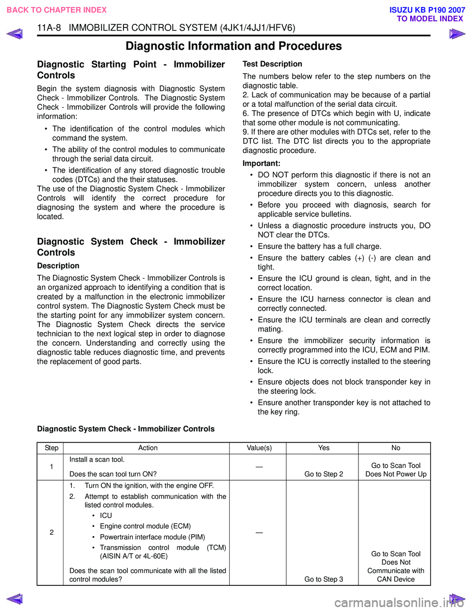
Begin the system diagnosis with Diagnostic System
Check - Immobilizer Controls. The Diagnostic System
Check - Immobilizer Controls will provide the following
information:
• The identification of the control modules which command the system.
• The ability of the control modules to communicate through the serial data circuit.
• The identification of any stored diagnostic trouble codes (DTCs) and the their statuses.
The use of the Diagnostic System Check - Immobilizer
Controls will identify the correct procedure for
diagnosing the system and where the procedure is
located.
Diagnostic System Check - Immobilizer
Controls
Description
The Diagnostic System Check - Immobilizer Controls is
an organized approach to identifying a condition that is
created by a malfunction in the electronic immobilizer
control system. The Diagnostic System Check must be
the starting point for any immobilizer system concern.
The Diagnostic System Check directs the service
technician to the next logical step in order to diagnose
the concern. Understanding and correctly using the
diagnostic table reduces diagnostic time, and prevents
the replacement of good parts. Test Description
The numbers below refer to the step numbers on the
diagnostic table.
2. Lack of communication may be because of a partial
or a total malfunction of the serial data circuit.
6. The presence of DTCs which begin with U, indicate
that some other module is not communicating.
9. If there are other modules with DTCs set, refer to the
DTC list. The DTC list directs you to the appropriate
diagnostic procedure.
Important: • DO NOT perform this diagnostic if there is not an immobilizer system concern, unless another
procedure directs you to this diagnostic.
• Before you proceed with diagnosis, search for applicable service bulletins.
• Unless a diagnostic procedure instructs you, DO NOT clear the DTCs.
• Ensure the battery has a full charge.
• Ensure the battery cables (+) (-) are clean and tight.
• Ensure the ICU ground is clean, tight, and in the correct location.
• Ensure the ICU harness connector is clean and correctly connected.
• Ensure the ICU terminals are clean and correctly mating.
• Ensure the immobilizer security information is correctly programmed into the ICU, ECM and PIM.
• Ensure the ICU is correctly installed to the steering lock.
• Ensure objects does not block transponder key in the steering lock.
• Ensure another transponder key is not attached to the key ring.
Diagnostic System Check - Immobilizer Controls
Step Action Value(s)Yes No
1 Install a scan tool.
Does the scan tool turn ON? —
Go to Step 2 Go to Scan Tool
Does Not Power Up
2 1. Turn ON the ignition, with the engine OFF.
2. Attempt to establish communication with the listed control modules.
•ICU
• Engine control module (ECM)
• Powertrain interface module (PIM)
• Transmission control module (TCM) (AISIN A/T or 4L-60E)
Does the scan tool communicate with all the listed
control modules? —
Go to Step 3 Go to Scan Tool
Does Not
Communicate with CAN Device
BACK TO CHAPTER INDEX TO MODEL INDEX
ISUZU KB P190 2007
Page 5896 of 6020
IMMOBILIZER CONTROL SYSTEM (4JK1/4JJ1/HFV6) 11A-45
Description and Operation
Immobilizer System Description
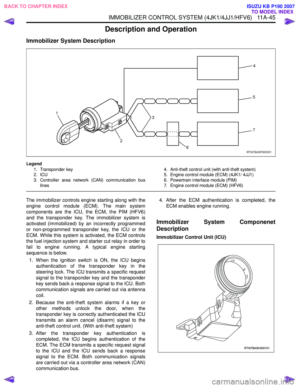
Legend1. Transponder key
2. ICU
3. Controller area network (CAN) communication bus lines 4. Anti-theft control unit (with anti-theft system)
5. Engine control module (ECM) (4JK1/ 4JJ1)
6. Powertrain interface module (PIM)
7. Engine control module (ECM) (HFV6)
The immobilizer controls engine starting along with the
engine control module (ECM). The main system
components are the ICU, the ECM, the PIM (HFV6)
and the transponder key. The immobilizer system is
activated (immobilized) by an incorrectly programmed
or non-programmed transponder key, the ICU or the
ECM. While this system is activated, the ECM controls
the fuel injection system and starter cut relay in order to
fail to engine running. A typical engine starting
sequence is below.
1. When the ignition switch is ON, the ICU begins authentication of the transponder key in the
steering lock. The ICU transmits a specific request
signal to the transponder key and the transponder
key sends back a response signal to the ICU. Both
communication signals are carried out via antenna
coil.
2. Because the anti-theft system alarms if a key or other methods unlock the door, when the
transponder key is correctly authenticated the ICU
transmits an alarm cancel (disarm) signal to the
anti-theft control unit. (With anti-theft system)
3. After the transponder key authentication is completed, the ICU begins authentication of the
ECM. The ECM transmits a specific request signal
to the ICU and the ICU sends back a response
signal to the ECM. Both communication signals
are carried out via a controller area network (CAN)
communication bus. 4. After the ECM authentication is completed, the
ECM enables engine running.
Immobilizer System Componenet
Description
Immobilizer Control Unit (ICU)
RTW7BASH000101
BACK TO CHAPTER INDEX TO MODEL INDEX
ISUZU KB P190 2007
Page 5897 of 6020
11A-46 IMMOBILIZER CONTROL SYSTEM (4JK1/4JJ1/HFV6)
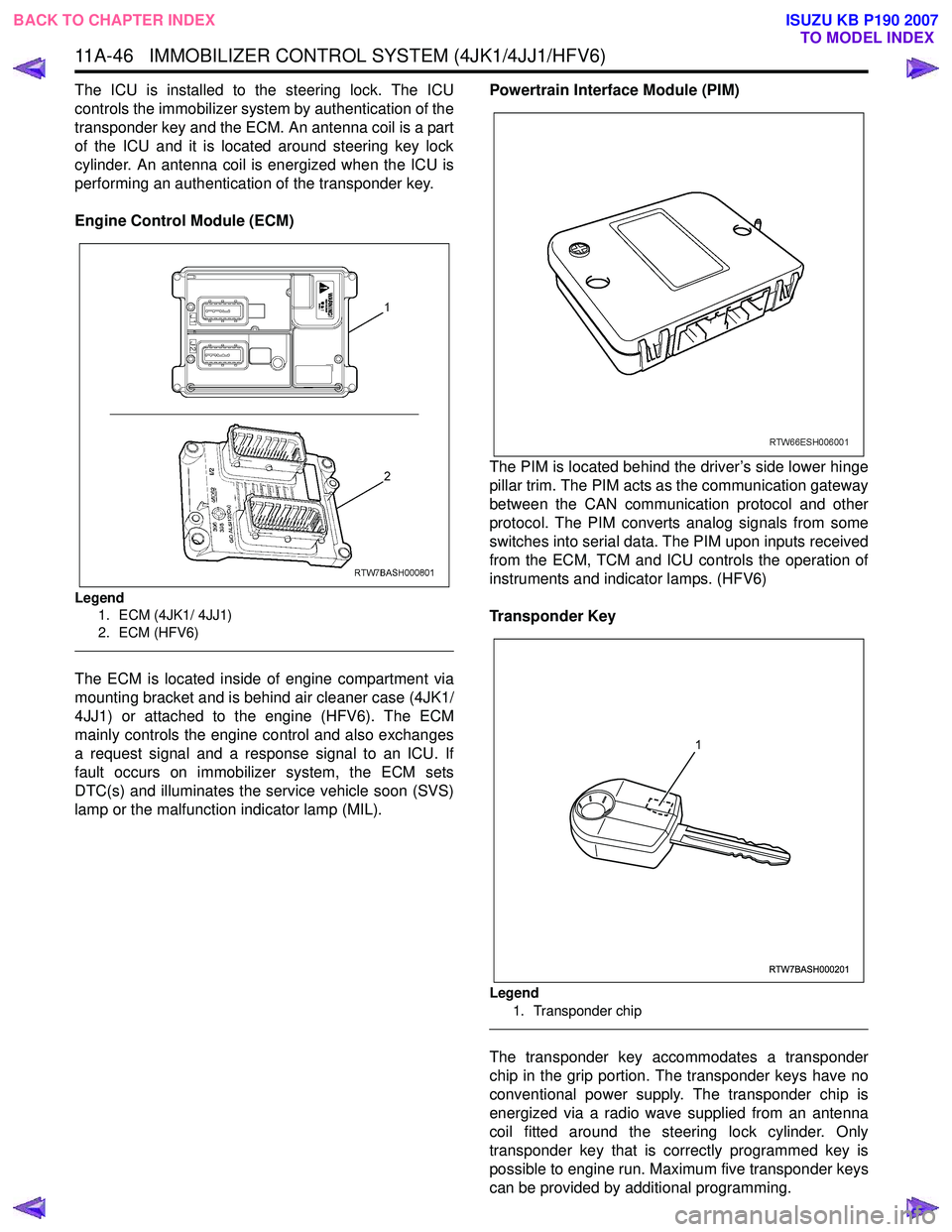
The ICU is installed to the steering lock. The ICU
controls the immobilizer system by authentication of the
transponder key and the ECM. An antenna coil is a part
of the ICU and it is located around steering key lock
cylinder. An antenna coil is energized when the ICU is
performing an authentication of the transponder key.
Engine Control Module (ECM)
Legend 1. ECM (4JK1/ 4JJ1)
2. ECM (HFV6)
The ECM is located inside of engine compartment via
mounting bracket and is behind air cleaner case (4JK1/
4JJ1) or attached to the engine (HFV6). The ECM
mainly controls the engine control and also exchanges
a request signal and a response signal to an ICU. If
fault occurs on immobilizer system, the ECM sets
DTC(s) and illuminates the service vehicle soon (SVS)
lamp or the malfunction indicator lamp (MIL). Powertrain Interface Module (PIM)
The PIM is located behind the driver’s side lower hinge
pillar trim. The PIM acts as the communication gateway
between the CAN communication protocol and other
protocol. The PIM converts analog signals from some
switches into serial data. The PIM upon inputs received
from the ECM, TCM and ICU controls the operation of
instruments and indicator lamps. (HFV6)
Transponder Key
Legend 1. Transponder chip
The transponder key accommodates a transponder
chip in the grip portion. The transponder keys have no
conventional power supply. The transponder chip is
energized via a radio wave supplied from an antenna
coil fitted around the steering lock cylinder. Only
transponder key that is correctly programmed key is
possible to engine run. Maximum five transponder keys
can be provided by additional programming.
RTW7BASH000201
1
BACK TO CHAPTER INDEX TO MODEL INDEX
ISUZU KB P190 2007