2007 ISUZU KB P190 power steering
[x] Cancel search: power steeringPage 3674 of 6020
Powertrain Interface Module – V6 Page 6E1–13
3.2 Powertrain Interface Module Gateway
Components
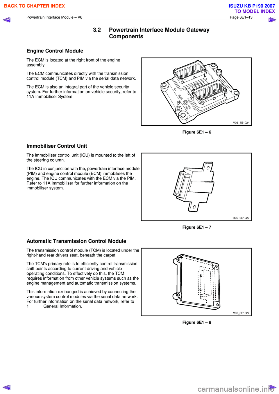
Engine Control Module
The ECM is located at the right front of the engine
assembly.
The ECM communicates directly with the transmission
control module (TCM) and PIM via the serial data network.
The ECM is also an integral part of the vehicle security
system. For further information on vehicle security, refer to
11A Immobiliser System.
Figure 6E1 – 6
Immobiliser Control Unit
The immobiliser control unit (ICU) is mounted to the left of
the steering column.
The ICU in conjunction with the, powertrain interface module
(PIM) and engine control module (ECM) immobilises the
engine. The ICU communicates with the ECM via the PIM.
Refer to 11A Immobiliser for further information on the
immobiliser system.
Figure 6E1 – 7
Automatic Transmission Control Module
The transmission control module (TCM) is located under the
right-hand rear drivers seat, beneath the carpet.
The TCM's primary role is to efficiently control transmission
shift points according to current driving and vehicle
operating conditions. To effectively do this, the TCM
requires information from other vehicle systems such as the
engine management and automatic transmission systems.
This information exchanged is achieved by connecting the
various system control modules via the serial data network.
For further information on the serial data network, refer to
1 General Information.
Figure 6E1 – 8
BACK TO CHAPTER INDEX
TO MODEL INDEX
ISUZU KB P190 2007
Page 3675 of 6020
Powertrain Interface Module – V6 Page 6E1–14
3.3 Powertrain Interface Module Direct Input
Switches
The following switches are direct wired to the PIM. These switches use the PIM to convert their input signals into serial
data, which is then used by the various vehicle control modules to perform varying functions.
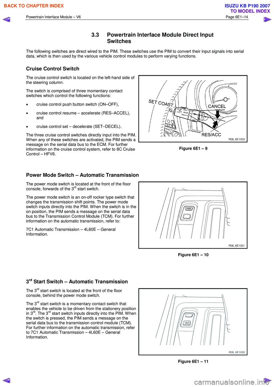
Cruise Control Switch
The cruise control switch is located on the left-hand side of
the steering column.
The switch is comprised of three momentary contact
switches which control the following functions:
• cruise control push button switch (ON–OFF),
• cruise control resume – accelerate (RES–ACCEL),
and
• cruise control set – decelerate (SET–DECEL).
The three cruise control switches directly input into the PIM.
W hen any of these switches are activated, the PIM sends a
message on the serial data bus to the ECM. For further
information on the cruise control system, refer to 8C Cruise
Control – HFV6.
Figure 6E1 – 9
Power Mode Switch – Automatic Transmission
The power mode switch is located at the front of the floor
console, forwards of the 3rd start switch.
The power mode switch is an on-off rocker type switch that
changes the transmission shift points. The power mode
switch inputs directly into the PIM. W hen the switch is in the
on position, the PIM sends a message on the serial data
bus to the Transmission Control Module (TCM). For further
information on the automatic transmission, refer to:
7C1 Automatic Transmission – 4L60E – General
Information.
Figure 6E1 – 10
3
rd Start Switch – Automatic Transmission
The 3rd start switch is located at the front of the floor
console, behind the power mode switch.
The 3
rd start switch is a momentary contact switch that
enables the vehicle to be driven from the stationery position
in 3
rd. The 3rd start switch inputs directly into the PIM. W hen
the switch is pressed, the PIM sends a message on the
serial data bus to the transmission control module (TCM).
For further information on the automatic transmission, refer
to 7C1 Automatic Transmission – 4L60E – General
Information.
Figure 6E1 – 11
BACK TO CHAPTER INDEX
TO MODEL INDEX
ISUZU KB P190 2007
Page 3785 of 6020
Automatic Transmission – 4L60E – General Information Page 7C1–25
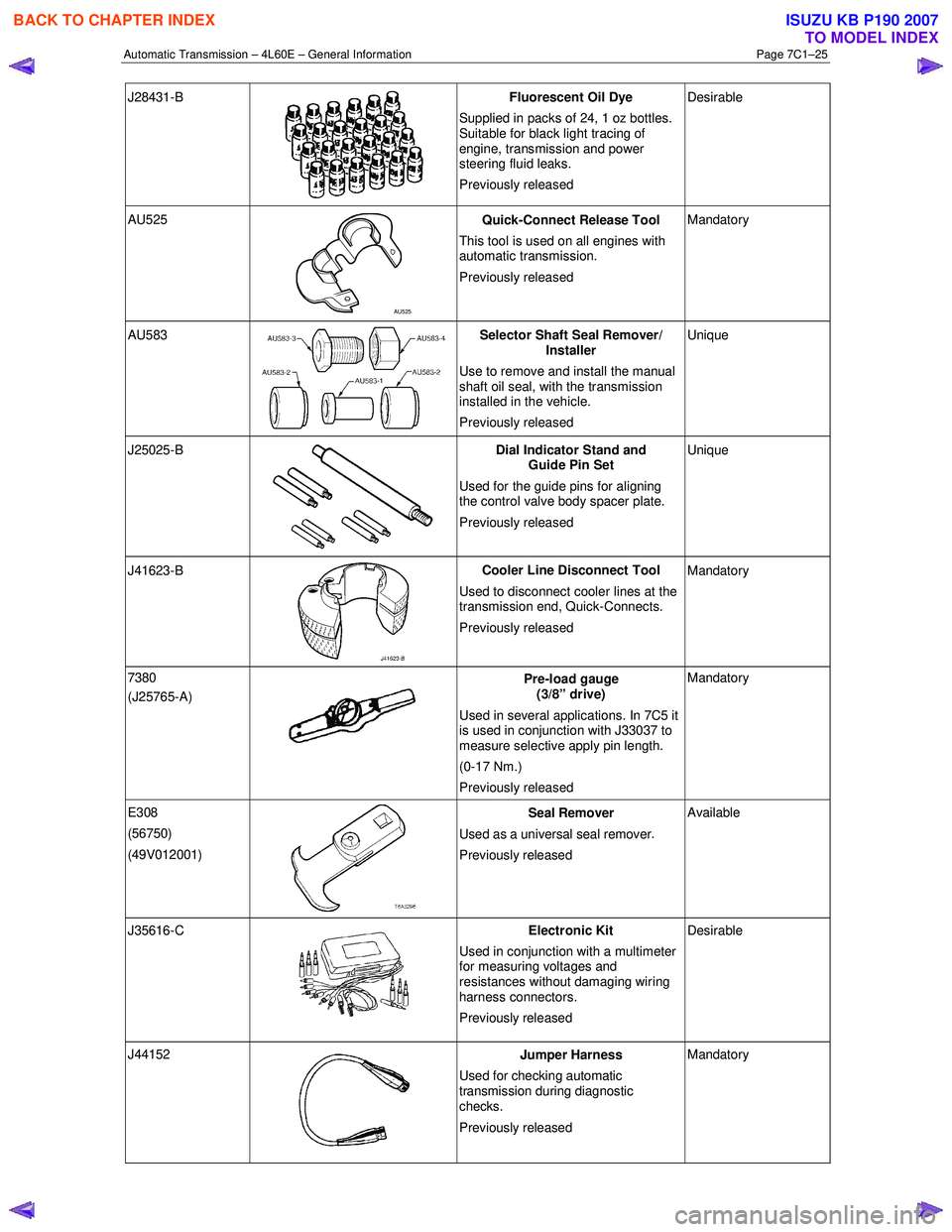
J28431-B
Fluorescent Oil Dye
Supplied in packs of 24, 1 oz bottles.
Suitable for black light tracing of
engine, transmission and power
steering fluid leaks.
Previously released Desirable
AU525
AU525 Quick-Connect Release Tool
This tool is used on all engines with
automatic transmission.
Previously released Mandatory
AU583 Selector Shaft Seal Remover/
Installer
Use to remove and install the manual
shaft oil seal, with the transmission
installed in the vehicle.
Previously released Unique
J25025-B
Dial Indicator Stand and
Guide Pin Set
Used for the guide pins for aligning
the control valve body spacer plate.
Previously released Unique
J41623-B
Cooler Line Disconnect Tool
Used to disconnect cooler lines at the
transmission end, Quick-Connects.
Previously released Mandatory
7380
(J25765-A)
Pre-load gauge
(3/8” drive)
Used in several applications. In 7C5 it
is used in conjunction with J33037 to
measure selective apply pin length.
(0-17 Nm.)
Previously released Mandatory
E308
(56750)
(49V012001)
Seal Remover
Used as a universal seal remover .
Previously released Available
J35616-C
Electronic Kit
Used in conjunction with a multimeter
for measuring voltages and
resistances without damaging wiring
harness connectors.
Previously released Desirable
J44152
Jumper Harness
Used for checking automatic
transmission during diagnostic
checks.
Previously released Mandatory
BACK TO CHAPTER INDEX
TO MODEL INDEX
ISUZU KB P190 2007
Page 5652 of 6020
SUPPLEMENTAL RESTRAINT SYSTEM 9A-17
“Continuous Monitoring”
Tests are performed by the SRS control unit on the
SRS every 100 milliseconds while “Ignition 1” voltage
is in the normal operating voltage range at the SRS
control unit.
Data Link Connector (DLC)
Formerly “DLC”, a connector which allows
communication with an external computer, such as a
scan tool.
Datum Line
A base line parallel to the plane of the underbody or
frame from which all vertical measurements originate.
Deploy
To inflate the air bag.
Deployment Loops
The circuits which supply current to the air bag
assemblies to deploy the air bag.
Diagnostic Trouble Code (DTC)
Formerly “Code”, a numerical designator used by the
SRS control unit to indicate specific SRS malfunctions.
Driver Current Source
An output of the SRS control unit which applies current
into the driver air bag assembly circuit during the
“Initiator Assembly Resistance Test”.
Driver Air Bag Assembly
An assembly located in the steering wheel hub
consisting of an inflatable bag, an inflator and an
initiator.
EEPROM
Electrically Erasable Programmable Read Onl
y
Memory. Memory which retains its contents when
power is removed from the SRS control unit.
Ignition Cycle
The voltage at the SRS control unit “Ignition 1” input,
with ignition switch “ON”, is within the normal operating
voltage range for at least ten seconds before turning
the ignition switch “OFF”.
Ignition 1
A battery voltage (B+) circuit which is only powered
when the ignition switch is in the ON, or START
position.
Initiator
The electrical component inside the air bag assembl
y
which, when sufficient current flows, sets off the
chemical reaction that inflates the air bag.
“Initiator Assembly Resistance Test”
Tests are performed once for each ignition cycle when
no malfunctions are detected during “Turn–ON” o
r
“Continuous Monitoring”. This test checks for the
correct SRS control unit configuration for the vehicle,
shorts to “Ignition 1” in the deployment loops, high
resistance or opens in the “Driver Side” and
“Passenger Side” circuits and measures the resistance
of the inflator assembly consisting of 1) Initiators, 2)
SRS coil assembly (driver side only), 3) Connectors
and associated wiring.
Normal Operating Voltage Range
The voltage measured between the SRS control unit
“Ignition 1” terminals and “Ground” terminals is
between 9 and 16 volts.
Passenger Current Source
An output of the SRS control unit which applies current
into the passenger air bag assembly circuit during the
“Initiator Assembly Resistance Test”.
Passenger Air Bag Assembly
An assembly located in the front of the passenger side
of the instrument panel consisting of an inflatable bag,
an inflator and an initiator.
Scan Tool
An external computer used to read diagnostic
information from on–board computers via the data link
connector.
SRS control unit
SRS control unit which provides reserve energy to the
deployment loops, deploys the air bags when required
and performs diagnostic monitoring of all SRS
components.
Serial Data
Information representing the status of the SRS.
SRS
Supplemental Restraint System.
SRS Coil Assembly
An assembly of two current–carrying coils in the drive
r
deployment loop that allows the rotation of the steering
wheel while maintaining the continuous contact of the
driver deployment loop to the driver air bag assembly.
SRS Wiring Harness
The wires and connectors that electrically connect the
components in the SRS.
“Turn–ON”
Test which the SRS control unit performs on the SRS
once during each ignition cycle immediately afte
r
“Ignition 1” voltage is applied to the SRS control unit
and before “Continuous Monitoring”.
BACK TO CHAPTER INDEX TO MODEL INDEXISUZU KB P190 2007
Page 5656 of 6020
SUPPLEMENTAL RESTRAINT SYSTEM 9A-21
On–Vehicle Service
Service Precaution
WARNING: WHEN PERFORMING SERVICE ON OR
AROUND SRS COMPONENTS OR SRS WIRING,
FOLLOW THE PROCEDURES LISTED BELOW TO
TEMPORARILY DISABLE THE SRS. FAILURE TO
FOLLOW PROCEDURES COULD RESULT IN
POSSIBLE AIR BAG DEPLOYMENT, PERSONAL
INJURY OR OTHERWISE UNNECESSARY SRS
REPAIRS.
The SRS control unit in Driver–Passenger SRS can
maintain sufficient voltage to cause a deployment fo
r
up to 15 seconds after the ignition switch is turned
“OFF,” the battery is disconnected, or the fuse
powering the SRS control unit is removed.
Many of the service procedures require removal of the
“SRS” fuse, and disconnection of the air bag assembl
y
from the deployment loop to avoid an accidental
deployment. If the air bag assembly is disconnected
from the deployment loop as noted in the “Disabling
the SRS” procedure that follows, service can begin
immediately without waiting for the 15 second time
period to expire.
Disabling The SRS
Removal
Turn the ignition switch to “LOCK” and remove the
key.
1. Remove the SRS fuse “SRS”, from the side of the driver’s side of the instrument panel fuse block o
r
disconnect the battery.
2. Disconnect the yellow connector at the base of the steering column.
3. Remove the glove box assembly, refer to “Passenger Air Bag Assembly Replacement” in
this manual.
4. Disconnect the yellow connector behind the glove box assembly.
CAUTION: With the “SRS” fuse removed and
ignition switched “ON”, the “SRS” warning lamp
will be “ON”. This is normal operation and does
not indicate an SRS malfunction.
Enabling The SRS
Installation
CAUTION: Never use the air bag assembly from
another vehicle or different model year air bag
assembly.
Use only a new air bag assembly matched to the
TFR/S which is being repaired.
Turn the ignition switch to “LOCK” and remove the
key.
1. Connect the yellow connector passenger air bag assembly.
2. Install the glove box assembly. Refer to “Passenger air bag assembly replacement” in this
manual.
3. Connect the yellow connector at the base of the steering column.
4. Install the “AIR BAG” fuse “SRS” to the side of the driver’s side of the instrument panel fuse block o
r
connect the battery.
Turn the ignition switch to “ON” and verify that the
“SRS” warning lamp flashes seven times and then
turns to “LOCK”. If it does not operate as described,
perform the “SRS Diagnostic System Check” in this
manual.
Handling / Installation / Diagnosis
1. The air bag assembly should not be subjected to temperatures above 65
°C (150°F).
2. The air bag assembly, and SRS control unit, should not be used if they have been dropped from
a height of 100 centimeters (3.28 feet) or more.
3. W hen the SRS control unit is replaced, it must be oriented with the arrow on the sensor pointing
toward the front of the vehicle. It is very important
for the SRS control unit to be located flat on the
mounting surface, parallel to the vehicle datum
line. It is important that the SRS control unit
mounting surface is free of any dirt or other foreign
material.
4. Do not apply power to the SRS unless all components are connected or a diagnostic chart
requests it, as this will set a diagnostic trouble
code.
5. The “SRS Diagnostic System Check” must be the starting point of any SRS diagnostics. The “SRS
Diagnostic System Check” will verify proper “SRS”
warning lamp operation and will lead you to the
correct chart to diagnose any SRS malfunctions.
Bypassing these procedures may result in
extended diagnostic time, incorrect diagnosis, and
incorrect parts replacement.
BACK TO CHAPTER INDEX TO MODEL INDEXISUZU KB P190 2007
Page 5663 of 6020
9A-28 SUPPLEMENTAL RESTRAINT SYSTEM
20. The passenger inflator requires no special
precaution after deployment. 95% of the
particulate emission is potassium chloride (KLC),
which is commonly sold as an edible salt-
substitute. Even if water is applied, post
deployment products are relatively pH neutral.
Disposing of the inflator by burying it in a landfill
will not produce any hazardous products. As with
any dusty environment, safety goggles, dust mask
and gloves should be worn.
WARNING: SAFETY PRECAUTIONS MUST BE
OBSERVED WHEN HANDLING A DEPLOYED AIR
BAG ASSEMBLY. AFTER DEPLOYMENT, THE
METAL SURFACES OF THE AIR BAG ASSEMBLY
WILL BE HOT. ALLOW THE AIR BAG ASSEMBLY
TO COOL BEFORE HANDLING ANY METAL
PORTION OF IT. DO NOT PLACE THE DEPLOYED
INFLATOR MODULE NEAR ANY FLAMMABLE
OBJECTS. FAILURE TO FOLLOW PROCEDURES
MAY RESULT IN FIRE OR PERSONAL INJURY.
AFTER AN AIR BAG ASSEMBLY HAS BEEN
DEPLOYED, THE METAL CANISTER AND
SURROUNDING AREAS OF THE AIR BAG
ASSEMBLY WILL BE HOT. DO NOT TOUCH THE
METAL AREAS OF THE AIR BAG ASSEMBLY FOR
ABOUT THIRTY MINUTES AFTER DEPLOYMENT.
IF THE DEPLOYED AIR BAG ASSEMBLY MUST BE
MOVED BEFORE IT IS COOL, WEAR GLOVES AND
HANDLE BY THE AIR BAG ITSELF.
21. Disconnect the pigtail adapter from the air bag assembly as soon after deployment as possible to
avoid damage to the pigtail adapter or SRS
deployment harness from contacting the hot ai
r
bag assembly canister. The pigtail adapter and
SRS deployment harness are designed to be
reused. They should, however, be inspected fo
r
damage after each deployment and replaced if
necessary.
22. Dispose of the deployed air bag assembly through normal refuse channels after it has cooled for at
least 30 minutes.
23. W ash your hands with mild soap and wate
r
afterward.
NOTE: The remaining steps are to be followed in the
unlikely event that the air bag assembly did not deplo
y
after following the above procedures.
24. Ensure that the SRS deployment harness has been disconnected from the power source and that
its two banana plugs have been shorted togethe
r
by fully seating one banana plug into the other.
25. Disconnect the pigtail adapter from the air bag assembly.
WARNING: WHEN STORING A LIVE AIR BAG
ASSEMBLY OR WHEN LEAVING A LIVE AIR BAG
ASSEMBLY UNATTENDED ON A BENCH OR
OTHER SURFACE, ALWAYS FACE THE BAG UP
AND AWAY FROM THE SURFACE. THIS IS
NECESSARY SO THAT A FREE SPACE IS
PROVIDED TO ALLOW THE AIR BAG TO EXPAND
IN THE UNLIKELY EVENT OF
ACCIDENTAL
DEPLOYMENT. FAILURE TO FOLLOW
PROCEDURES MAY RESULT IN PERSONAL
INJURY.
26. Temporarily store the air bag assembly with the bag facing up, away from the surface upon which it
rests.
Deployment Inside Vehicle (Vehicle
Scrapping Procedure)
Deployment inside the vehicle is proper when the
vehicle is to be destroyed or salvaged for component
parts. This includes, but is not limited to, the following
situations:
1. The vehicle has completed its useful life.
2. The vehicle has been damaged beyond repair in a nondeployment type accident.
3. The vehicle has been stripped or damaged beyond repair in a theft.
4. The vehicle will be salvaged for component parts to be used on a vehicle with a different Vehicle
Identification Number (VIN) as opposed to being
rebuilt with the same VIN. Never use SRS
components from another vehicle.
WARNING: FAILURE TO FOLLOW PROPER SRS
AIR BAG ASSEMBLY DISPOSAL PROCEDURES
CAN RESULT IN AIR BAG DEPLOYMENT WHICH
MAY CAUSE PERSONAL INJURY. UNDEPLOYED
AIR BAG ASSEMBLIES MUST NOT BE DISPOSED
OF THROUGH NORMAL REFUSE CHANNELS.
THE UNDEPLOYED AIR BAG ASSEMBLY
CONTAINS SUBSTANCES THAT CAN CAUSE
SEVERE ILLNESS OR PERSONAL INJURY IF THE
SEALED CONTAINER IS DAMAGED DURING
DISPOSAL. DISPOSAL IN ANY MANNER
INCONSISTENT WITH PROPER PROCEDURES
MAY BE A VIOLATION OF FEDERAL, STATE
AND/OR LOCAL LAWS.
1. Turn the ignition switch to “LOCK,” remove the ke
y
and put on the safety glasses.
2. Remove all loose objects from the front seats.
3. Disconnect the driver air bag assembly yello
w
connector located at the base of the steering
column.
4. Cut the driver air bag assembly yellow harness connector from the vehicle leaving at least 15 cm
(six inches) of wire at the connector.
BACK TO CHAPTER INDEX TO MODEL INDEXISUZU KB P190 2007
Page 5664 of 6020
SUPPLEMENTAL RESTRAINT SYSTEM 9A-29
5. Strip 13 mm (1/2 inch) of insulation from the yellow
– green and yellow – black wire lead of the
connector.
6. Cut two 900 cm (30 feet) deployment wires from 0.8 mm
2 (18 gauge) or thicker multi–strand wire.
These wires will be used to fabricate the drive
r
deployment harness.
7. Strip 13 mm (1/2 inch) of insulation from both ends of the wires cut in the previous step.
8. Short the wires by twisting together one end from each. Deployment wires shall remain shorted and
not be connected to a power source until the ai
r
bag is to be deployed.
WARNING: FAILURE TO FOLLOW PROCEDURES
IN THE ORDER LISTED COULD RESULT IN
PERSONAL INJURY. NEVER CONNECT
DEPLOYMENT WIRES TO ANY POWER SOURCE
BEFORE CONNECTING DEPLOYMENT WIRES TO
THE AIR BAG ASSEMBLY LEADS. DEPLOYMENT
WIRES SHALL REMAIN SHORTED AND NOT BE
CONNECTED TO A POWER SOURCE UNTIL THE
AIR BAG IS TO BE DEPLOYED. THE AIR BAG
ASSEMBLY WILL IMMEDIATELY DEPLOY THE AIR
BAG WHEN A POWER SOURCE IS CONNECTED
TO IT. WEAR SAFETY GLASSES THROUGHOUT
THIS ENTIRE DEPLOYMENT AND DISPOSAL
PROCEDURE.
9. Twist together one connector wire lead to one deployment wire. The connection should be
mechanically secure.
10. Bend the twisted connection made in the previous step flat and wrap it tightly with electrical tape to
insulate and secure.
11. Twist together, bend and tape the remaining connector wire lead to the remaining deployment
wire.
12. Connect the deployment harness to the driver ai
r
bag assembly yellow connector at the base of the
steering column. Route the deployment harness
out through the driver’s side of the vehicle.
WARNING: DEPLOYMENT WIRES SHALL REMAIN
SHORTED AND NOT BE CONNECTED TO
A
POWER SOURCE UNTIL THE AIR BAG IS TO BE
DEPLOYED.
THE AIR BAG ASSEMBLY WILL IMMEDIATELY
DEPLOY THE AIR BAG WHEN A POWER SOURCE
IS CONNECTED TO IT.
Connecting the deployment wires to the powe
r
source should always be the final step in the ai
r
bag assembly deployment procedure.
Failure to follow procedures in the order listed
could result in personal injury.
13. Disconnect the passenger air bag assembly yello
w
connector located behind the glove box assembly.
14. Cut the passenger air bag assembly harness
connector from the vehicle leaving at least 15 cm
(six inches) of wire at the connector.
15. Strip 13 mm (1/2 inch) of insulation from the blue– white and pink–blue wire lead of the connector.
16. Cut two 900 cm (30 feet) deployment wires from 0.8 mm
2 (18 gauge) or thicker multi–strand wire.
These wires will be used to fabricate the
passenger deployment harness.
17. Strip 13 mm (1/2 inch) of insulation from both ends of the wires cut in the previous step.
18. Short the wires by twisting together one end from each. The deployment wires shall remain shorted
and not be connected to a power source until the
air bag is to be deployed.
WARNING: FAILURE TO FOLLOW PROCEDURES
IN THE ORDER LISTED COULD RESULT IN
PERSONAL INJURY. NEVER CONNECT
DEPLOYMENT WIRES TO ANY POWER SOURCE
BEFORE CONNECTING DEPLOYMENT WIRES TO
THE AIR BAG ASSEMBLY LEADS. DEPLOYMENT
WIRES SHALL REMAIN SHORTED AND NOT BE
CONNECTED TO A POWER SOURCE UNTIL THE
AIR BAG IS TO BE DEPLOYED. THE AIR BAG
ASSEMBLY WILL IMMEDIATELY DEPLOY THE AIR
BAG WHEN A POWER SOURCE IS CONNECTED
TO IT. WEAR SAFETY GLASSES THROUGHOUT
THIS ENTIRE DEPLOYMENT AND DISPOSAL
PROCEDURE.
19. Twist together one connector wire lead to one deployment wire. The connection should be
mechanically secure.
20. Bend the twisted connection made in the previous step flat and wrap it tightly with electrical tape to
insulate and secure.
21. Twist together, bend and tape the remaining connector wire lead to the remaining deployment
wire.
22. Connect the deployment harness to the passenge
r
air bag assembly yellow connector located behind
the glove box assembly. Route the deployment
harness out through the passenger side of the
vehicle.
WARNING: DEPLOYMENT WIRES SHALL REMAIN
SHORTED AND NOT BE CONNECTED TO
A
POWER SOURCE UNTIL THE AIR BAG IS TO BE
DEPLOYED. THE AIR BAG ASSEMBLY WILL
IMMEDIATELY DEPLOY THE AIR BAG WHEN
A
POWER SOURCE IS CONNECTED TO IT.
CONNECTING THE DEPLOYMENT WIRES
SHOULD ALWAYS BE THE FINAL STEP IN THE
AIR BAG ASSEMBLY DEPLOYMENT PROCEDURE.
FAILURE TO FOLLOW PROCEDURES IN THE
ORDER LISTED COULD RESULT IN PERSONAL
INJURY.
BACK TO CHAPTER INDEX TO MODEL INDEXISUZU KB P190 2007
Page 5667 of 6020
9A-32 SUPPLEMENTAL RESTRAINT SYSTEM
Service Precautions for SRS
Component Service
CAUTION: When fasteners are removed, always
reinstall them at the same location from which
they were removed. If a fastener needs to be
replaced, use the correct part number fastener fo
r
that application. If the correct part number
fastener is not available, a fastener of equal size
and strength (or stronger) may be used. Fasteners
that are not reused, and those requiring a thread
locking compound will be called out. The correct
torque value must be used when installing
fasteners that require it. If the above conditions
are not followed, parts or system damage could
result.
WARNING: WHEN PERFORMING SERVICE ON OR
AROUND SRS COMPONENTS OR SRS WIRING,
FOLLOW THE PROCEDURES LISTED BELOW TO
TEMPORARILY DISABLE THE SRS. FAILURE TO
FOLLOW PROCEDURES COULD RESULT IN
POSSIBLE AIR BAG DEPLOYMENT, PERSONAL
INJURY OR OTHERWISE UNNEEDED SRS
REPAIRS.
The SRS control unit in the Driver–Passenger SRS
can maintain sufficient voltage to cause a deployment
for up to 15 seconds after the ignition switch is turned
“OFF,” the battery is disconnected, or the fuse
powering the SRS control unit is removed.
Many of the service procedures require removal of the
“SRS” fuse, and disconnection of the air bag assembl
y
from the deployment loop to avoid an accidental
deployment. If the air bag assembly is disconnected
from the deployment loop as noted in the “Disabling
the SRS” procedure that follows, service can begin
immediately without waiting for the 15 second time
period to expire.
Disabling The SRS
Removal
Turn the ignition switch to “OFF” and turn the steering
wheel so that the vehicle's wheels are pointing straight
ahead.
1. Remove the SRS fuse “SRS” from the left dash side lower fuse block or disconnect the battery.
2. Disconnect the yellow connector at the base o
f
steering column.
3. Remove the glove box assembly; Refer to “Passenger air bag assembly replacement” in this
section.
4. Disconnect the passenger air bag assembly yello
w
connector behind the glove box assembly.
CAUTION: With the “SRS” fuse removed and the
ignition switch to “ON,” the “SRS” warning lamp
will be “ON.” This is normal operation and does
not indicate an SRS malfunction.
Enabling The SRS
Installation
Turn the ignition switch to “LOCK” and remove the
key.
1. Connect the yellow connector passenger air bag assembly.
2. Install the glove box assembly. Refer to “Passenger Air Bag Assembly Replacement” in
this section.
3. Connect the yellow connector at the base of the steering column.
4. Install the “AIR BAG” fuse “SRS” to the left dash side lower fuse block or connect the battery.
Turn the ignition switch to “ON” and verify that the
“SRS” warning lamp flashes seven times and then
turns to “LOCK”. If it does not operate as described,
perform the “SRS Diagnostic System Check” in this
section.
Handling / Installation / Diagnosis
1. Air bag assembly should not be subjected to
temperatures above 65 °C (150 °F).
2.
Air bag assembly, and SRS control unit should not
be used if they have been dropped from a height
of 100 centimeters (3.28 feet) or more.
3. W hen a SRS control unit is replaced, it must be oriented with the arrow on the SRS control unit
pointing toward the front of the vehicle. It is ver
y
important for the SRS control unit to be located flat
on the mounting surface, parallel to the vehicle
datum line. It is important that the SRS control unit
mounting surface is free of any dirt or other foreign
material.
4. Do not apply power to the SRS unless all components are connected or a diagnostic chart
requests it, as this will set a diagnostic trouble
code.
5. The “SRS Diagnostic System Check” must be the starting point of any SRS diagnostics. The “SRS
Diagnostic System Check” will verify proper “SRS”
warning lamp operation and will lead you to the
correct chart to diagnose any SRS malfunctions.
Bypassing these procedures may result in
extended diagnostic time, incorrect diagnosis, and
incorrect parts replacements.
BACK TO CHAPTER INDEX TO MODEL INDEXISUZU KB P190 2007