2007 ISUZU KB P190 power steering
[x] Cancel search: power steeringPage 2772 of 6020
Engine Mechanical – V6 Page 6A1–293
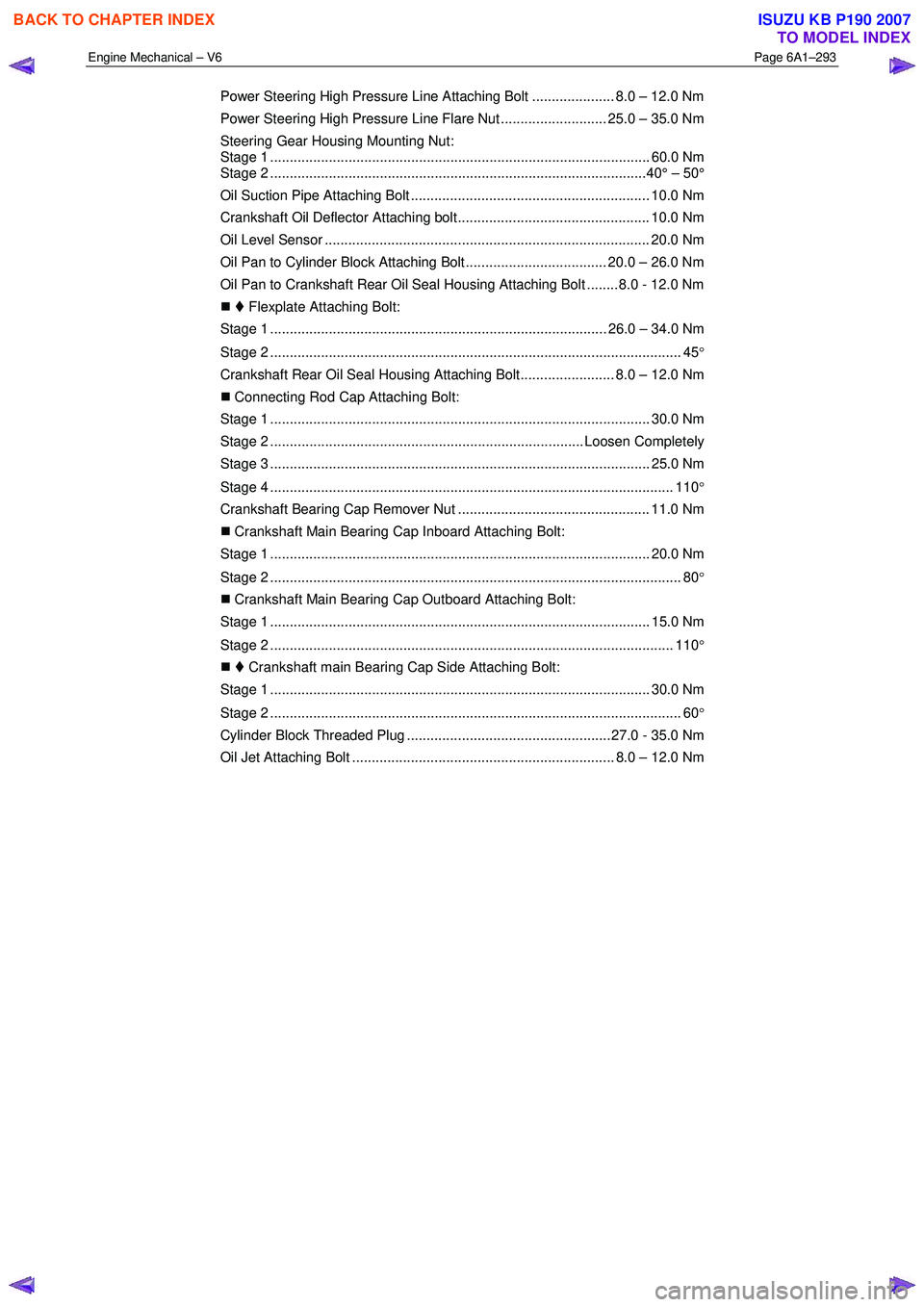
Power Steering High Pressure Line Attaching Bolt ..................... 8.0 – 12.0 Nm
Power Steering High Pressure Line Flare Nut ........................... 25.0 – 35.0 Nm
Steering Gear Housing Mounting Nut:
Stage 1 ................................................................................................. 60.0 Nm
Stage 2 ................................................................................................40° – 50°
Oil Suction Pipe Attaching Bolt ............................................................. 10.0 Nm
Crankshaft Oil Deflector Attaching bolt................................................. 10.0 Nm
Oil Level Sensor ................................................................................... 20.0 Nm
Oil Pan to Cylinder Block Attaching Bolt .................................... 20.0 – 26.0 Nm
Oil Pan to Crankshaft Rear Oil Seal Housing Attaching Bolt ........ 8.0 - 12.0 Nm
�„ Flexplate Attaching Bolt:
Stage 1 ...................................................................................... 26.0 – 34.0 Nm
Stage 2 ......................................................................................................... 45 °
Crankshaft Rear Oil Seal Housing Attaching Bolt........................ 8.0 – 12.0 Nm
�„ Connecting Rod Cap Attaching Bolt:
Stage 1 ................................................................................................. 30.0 Nm
Stage 2 ................................................................................ Loosen Completely
Stage 3 ................................................................................................. 25.0 Nm
Stage 4 ....................................................................................................... 110 °
Crankshaft Bearing Cap Remover Nut ................................................. 11.0 Nm
�„ Crankshaft Main Bearing Cap Inboard Attaching Bolt:
Stage 1 ................................................................................................. 20.0 Nm
Stage 2 ......................................................................................................... 80 °
�„ Crankshaft Main Bearing Cap Outboard Attaching Bolt:
Stage 1 ................................................................................................. 15.0 Nm
Stage 2 ....................................................................................................... 110 °
�„ Crankshaft main Bearing Cap Side Attaching Bolt:
Stage 1 ................................................................................................. 30.0 Nm
Stage 2 ......................................................................................................... 60 °
Cylinder Block Threaded Plug .................................................... 27.0 - 35.0 Nm
Oil Jet Attaching Bolt ................................................................... 8.0 – 12.0 Nm
BACK TO CHAPTER INDEX
TO MODEL INDEX
ISUZU KB P190 2007
Page 2780 of 6020
Engine Mechanical – V6 Page 6A1–3
Page 6A1–3
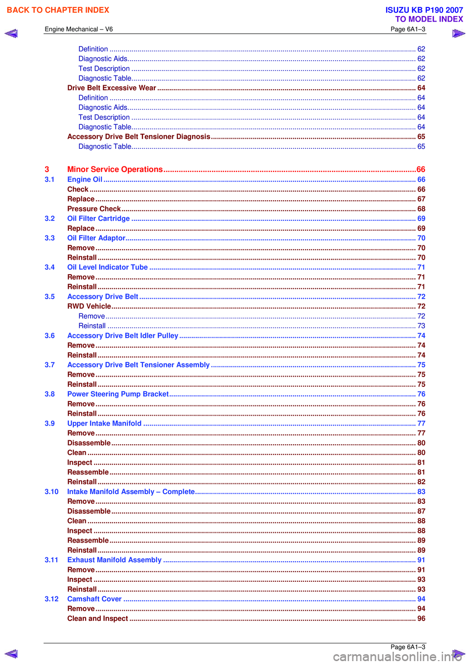
Definition ..................................................................................................................... .....................................62
Diagnostic Aids................................................................................................................................................. 62
Test Description ............................................................................................................... ................................62
Diagnostic Table............................................................................................................... ................................62
Drive Belt Excessive Wear ...................................................................................................... ............................64
Definition ..................................................................................................................... .....................................64
Diagnostic Aids................................................................................................................................................. 64
Test Description ............................................................................................................... ................................64
Diagnostic Table............................................................................................................... ................................64
Accessory Drive Belt Tensioner Diagnosis ....................................................................................... ................65
Diagnostic Table............................................................................................................... ................................65
3 Minor Service Operations ....................................................................................................... .............66
3.1 Engine Oil ..................................................................................................................... ........................................66
Check.................................................................................................................................................................... 66
Replace ........................................................................................................................ .........................................67
Pressure Check ................................................................................................................. ...................................68
3.2 Oil Filter Cartridge ........................................................................................................... ....................................69
Replace ........................................................................................................................ .........................................69
3.3 Oil Filter Adaptor............................................................................................................. .....................................70
Remove ................................................................................................................................................................. 70
Reinstall ................................................................................................................................................................ 70
3.4 Oil Level Indicator Tube ...................................................................................................................................... 71
Remove ................................................................................................................................................................. 71
Reinstall ................................................................................................................................................................ 71
3.5 Accessory Drive Belt ........................................................................................................................................... 72
RWD Vehicle ......................................................................................................................................................... 72
Remove ............................................................................................................................................................72
Reinstall ...................................................................................................................... .....................................73
3.6 Accessory Drive Belt Idler Pulley .............................................................................................. .........................74
Remove ................................................................................................................................................................. 74
Reinstall ................................................................................................................................................................ 74
3.7 Accessory Drive Belt Tensioner Assembly ........................................................................................ ...............75
Remove ................................................................................................................................................................. 75
Reinstall ................................................................................................................................................................ 75
3.8 Power Steering Pump Bracket .................................................................................................... ........................76
Remove ................................................................................................................................................................. 76
Reinstall ................................................................................................................................................................ 76
3.9 Upper Intake Manifold .......................................................................................................... ...............................77
Remove ................................................................................................................................................................. 77
Disassemble ......................................................................................................................................................... 80
Clean..................................................................................................................................................................... 80
Inspect ........................................................................................................................ ..........................................81
Reassemble .......................................................................................................................................................... 81
Reinstall ................................................................................................................................................................ 82
3.10 Intake Manifold Assembly – Complete............................................................................................ ...................83
Remove ................................................................................................................................................................. 83
Disassemble ......................................................................................................................................................... 87
Clean..................................................................................................................................................................... 88
Inspect ........................................................................................................................ ..........................................88
Reassemble .......................................................................................................................................................... 89
Reinstall ................................................................................................................................................................ 89
3.11 Exhaust Manifold Assembly ...................................................................................................... .........................91
Remove ................................................................................................................................................................. 91
Inspect ........................................................................................................................ ..........................................93
Reinstall ................................................................................................................................................................ 93
3.12 Camshaft Cover ................................................................................................................. ..................................94
Remove ................................................................................................................................................................. 94
Clean and Inspect .............................................................................................................. ..................................96
BACK TO CHAPTER INDEX
TO MODEL INDEX
ISUZU KB P190 2007
Page 2825 of 6020

Engine Mechanical – V6 Page 6A1–48
Page 6A1–48
2.18 Engine Oil Leak Diagnosis
Introduction
It is important to correctly identify the source of an engine oil leak. For example, a power steering fluid leak or spillage
during servicing can travel across the va lley area of the engine and run-out the weep hole, which is located at the back of
the cylinder block. Failure to correctly identify the source of an engine oil leak can lead to unnecessary replacement of
engine components.
Most fluid leaks can be repaired by repairi ng or replacing the faulty component or resealing the gasket surface. However,
once a leak is identified it is im portant to determine and repair the c ause as well as the leak itself.
Locating and Identifying the Leak
Inspect the leaking fluid and determine whet her it is engine oil, transmission fluid, power steering fluid, brake fluid or
some other fluid. If unsure of the source of the leaking lubricant, a quick check of fluid levels should indicate where the
fluid is coming from, as one or more fluid level should be low.
Visual Inspection
Once the type of leaking fluid has been determined, a visual inspection of the affected system should be performed.
When performing the visual inspection:
1 Bring the vehicle to the normal operating temperature.
2 Park the vehicle over a large s heet of paper or other clean surface.
3 Leave the vehicle idling for 2-3 minut es, then check for dripping fluid.
4 If required, identify the type of fluid leak ing and the approximate location of the leak.
5 Visually inspect the suspected area. A small mirror may assist viewing areas that are difficult to see normally.
6 Check for leaks at all sealing surfaces and fittings.
7 Check for any cracked or damaged components.
8 If the leak cannot be located, completely clean the entire engine and surrounding components, drive the vehicle at
normal operating temperature for several k ilometres and then repeat Steps 3 to 8.
9 If the leak still cannot be located, proceed with either the Powder Method or Black Light and Dye Method as
outlined below.
Powder Method
1 Completely clean the entir e engine and surrounding components.
2 Apply an aerosol type powder (e.g. f oot powder) to the suspected area.
3 Operate the vehicle at normal operating temperature and at varying speeds for several kilometres.
4 Identify the source of the leak from the discoloration of the powder around the suspect components.
5 If required, use a small mirror to assist in vi ewing areas that are difficult to see normally.
6 Refer to Possible Causes for Engine Oil Leaks in this Section, and repair or replace components as required.
Black Light and Dye Method
A black light and die kit Tool No. J28428-E or a commercially av ailable equivalent is available to technicians to aid in
engine oil leak diagnosis. When using a black light and die kit fo r the first time, it is recommended the technician read the
manufacturers instructions prior to using the kit.
1 Add the specified amount of dye, as per manufacturers instructions, into the engine or suspected source of the oil
leak.
2 Operate the vehicle at normal operating temperature and at varying speeds for several kilometres.
3 With the vehicle parked on a flat leve l surface, aim the black light at the suspected component/s. The dyed fluid will
appear as a yellow path leading to the oil leak source
4 Refer to Possible Causes for Engine Oil Leaks in this Section, and repair or replace components as required.
BACK TO CHAPTER INDEX
TO MODEL INDEX
ISUZU KB P190 2007
Page 2832 of 6020
Engine Mechanical – V6 Page 6A1–55
Page 6A1–55
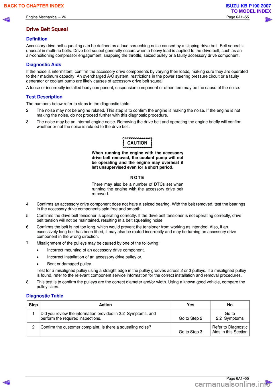
Drive Belt Squeal
Definition
Accessory drive belt squealing can be defined as a loud screeching noise caused by a slipping drive belt. Belt squeal is
unusual in multi-rib belts. Drive belt squeal generally occurs when a heavy load is applied to the drive belt, such as an
air-conditioning compressor engagement, snapping the throttle, se ized pulley or a faulty accessory drive component.
Diagnostic Aids
If the noise is intermittent, confirm the accessory drive components by varying t heir loads, making sure they are operated
to their maximum capacity. An overcharged A/C system, restrictions in the power steering pressure circuit or a faulty
generator or coolant pump are likely c auses of accessory drive belt squeal.
A loose or incorrectly installed body component, suspension component or other item may be the cause of the noise.
Test Description
The numbers below refer to steps in the diagnostic table.
2 The noise may not be engine related. This step is to confirm the engine is making t he noise. If the engine is not
making the noise, do not proceed further with this diagnostic procedure.
3 The noise may be an internal engine noise. Removing the drive belt and operating the engine briefly will confirm
whether or not the noise is related to the drive belt.
CAUTION
When running the engine with the accessory
drive belt removed, the coolant pump will not
be operating and the engine may overheat if
left unsupervised even for a short period.
NOTE
There may also be a number of DTCs set when
running the engine with the accessory drive belt
removed.
4 Confirms an accessory drive component does not have a se ized bearing. With the belt removed, test the bearings
in the accessory drive co mponents spin free and smooth.
5 Confirms the drive belt tensioner is operating correctly. If the drive belt tensioner is not operating correctly, drive
belt tension will not be maintained, resulting in a belt squealing noise
6 Confirms the belt is not too long, which would prevent the tensioner from working as intended. Also, if an
excessively long belt has been fitted, it may also be r outed incorrectly and may be turning an accessory drive
component in the wrong direction.
7 Misalignment of the pulleys may be caused by one of the following:
• Incorrect mounting of an accessory drive component,
• Incorrect installation of an accessory drive pulley or,
• Bent or damaged pulley.
Test for a misaligned pulley using a straight edge in the pulley grooves across 2 or 3 pulleys. If a misaligned pulley is found, refer to the relevant component service info rmation for the correct installation and removal procedures.
8 This test is to confirm the pulleys are the correct di ameter and/or width. Using a known good vehicle, compare the
pulley sizes.
Diagnostic Table
Step Action Yes No
1
Did you review the information provided in 2.2 Symptoms, and
perform the required inspections. Go to Step 2 Go to
2.2 Symptoms
2 Confirm the customer compla int. Is there a squealing noise?
Go to Step 3 Refer to Diagnostic
Aids in this Section
BACK TO CHAPTER INDEX
TO MODEL INDEX
ISUZU KB P190 2007
Page 2834 of 6020
Engine Mechanical – V6 Page 6A1–57
Page 6A1–57
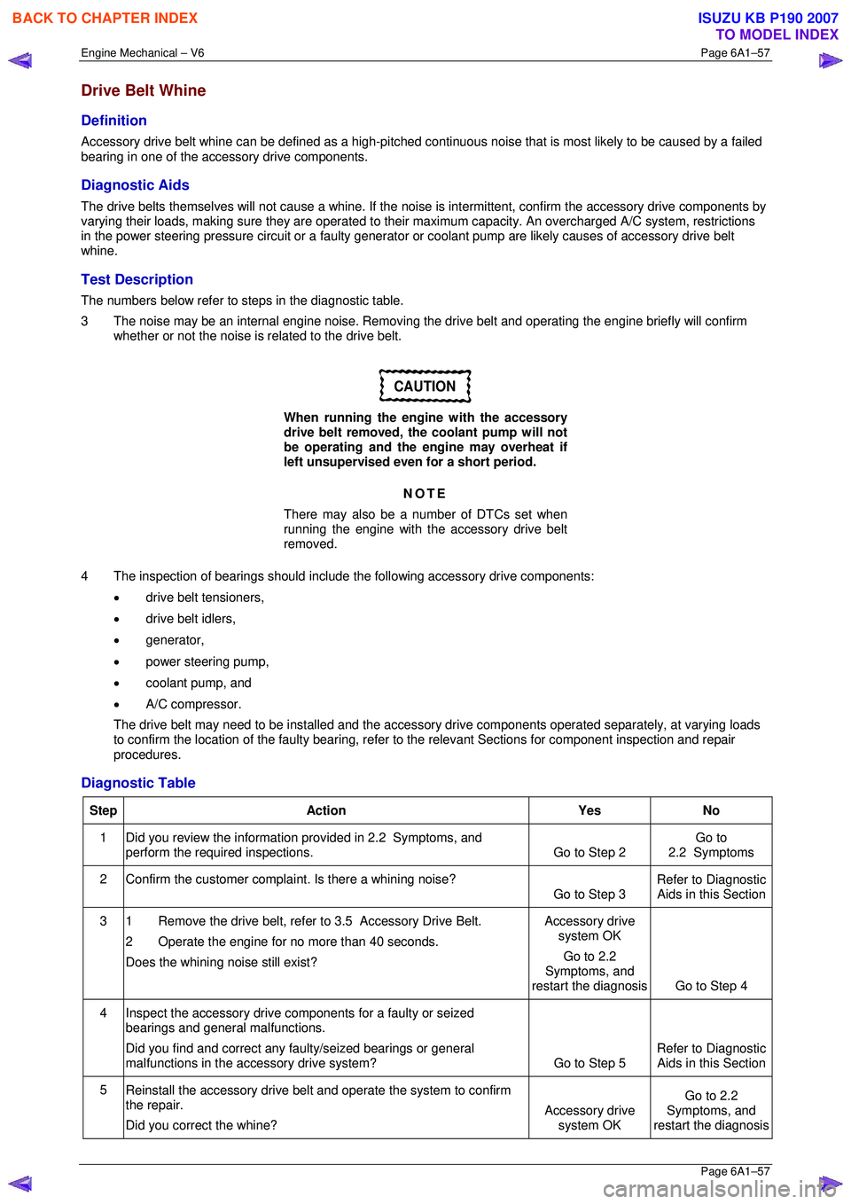
Drive Belt Whine
Definition
Accessory drive belt whine can be defined as a high-pitched continuous noise that is most likely to be caused by a failed
bearing in one of the acce ssory drive components.
Diagnostic Aids
The drive belts themselves will not caus e a whine. If the noise is intermittent, confirm the accessory drive components by
varying their loads, making sure they are operated to their maximum capacity. An overcharged A/C system, restrictions
in the power steering pressure circuit or a faulty generator or coolant pump ar e likely causes of accessory drive belt
whine.
Test Description
The numbers below refer to steps in the diagnostic table.
3 The noise may be an internal engine noise. Removing the drive belt and operating the engine briefly will confirm
whether or not the noise is related to the drive belt.
CAUTION
When running the engine with the accessory
drive belt removed, the coolant pump will not
be operating and the engine may overheat if
left unsupervised even for a short period.
NOTE
There may also be a number of DTCs set when
running the engine with the accessory drive belt
removed.
4 The inspection of bearings should include the following accessory drive components:
• drive belt tensioners,
• drive belt idlers,
• generator,
• power steering pump,
• coolant pump, and
• A/C compressor.
The drive belt may need to be installed and the accessory drive components operated separ ately, at varying loads
to confirm the location of the faulty bearing, refer to the relevant Sections for component inspection and repair
procedures.
Diagnostic Table
Step Action Yes No
1
Did you review the information provided in 2.2 Symptoms, and
perform the required inspections. Go to Step 2 Go to
2.2 Symptoms
2 Confirm the customer compla int. Is there a whining noise?
Go to Step 3 Refer to Diagnostic
Aids in this Section
3 1 Remove the drive belt, refer to 3.5 Accessory Drive Belt.
2 Operate the engine for no more than 40 seconds.
Does the whining noise still exist? Accessory drive
system OK
Go to 2.2
Symptoms, and
restart the diagnosis Go to Step 4
4 Inspect the accessory drive components for a faulty or seized
bearings and general malfunctions.
Did you find and correct any faulty/seized bearings or general
malfunctions in the accessory drive system? Go to Step 5 Refer to Diagnostic
Aids in this Section
5 Reinstall the accessory drive belt and operate the system to confirm
the repair.
Did you correct the whine? Accessory drive
system OK Go to 2.2
Symptoms, and
restart the diagnosis
BACK TO CHAPTER INDEX
TO MODEL INDEX
ISUZU KB P190 2007
Page 2850 of 6020
Engine Mechanical – V6 Page 6A1–73
Page 6A1–73
Reinstall
1 Install the drive belt over the A/C compressor, idler pulley, power steering pump, coolant pump, generator and
tensioner pulleys.
2 Using a suitable ½” drive socket bar (1), rotate the driv e belt tensioner (2) clockwise, refer to Figure 6A1 – 30.
3 With an assistant holding the tensi oner in the required position, feed the accessory drive belt (3) over the
crankshaft pulley.
4 Slowly release the drive belt tensioner mechanism.
NOTE
Ensure the drive belt ribs are correctly aligned
with the grooves in the accessory drive pulleys or
damage to the drive belt and accessory drive
components and pulleys may occur.
5 Reinstall the air intake duct to the ai r flow meter and the throttle body, refer to Section 6C1-3 Engine Management
– V6 – Service Operations .
6 Run the engine to ensure correct operation.
BACK TO CHAPTER INDEX
TO MODEL INDEX
ISUZU KB P190 2007
Page 2853 of 6020
Engine Mechanical – V6 Page 6A1–76
Page 6A1–76
3.8 Power Steering Pump Bracket
Remove
1 Remove the power steering pump and reservoir, refer to Section 3B Steering.
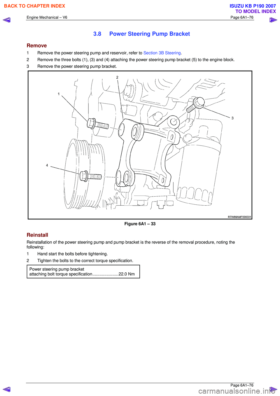
2 Remove the three bolts (1), (3) and (4) attaching t he power steering pump bracket (5) to the engine block.
3 Remove the power steering pump bracket.
Figure 6A1 – 33
Reinstall
Reinstallation of the power steering pump and pump bracket is the reverse of the removal procedure, noting the
following:
1 Hand start the bolts before tightening.
2 Tighten the bolts to the co rrect torque specification.
Power steering pump bracket
attaching bolt torque specification ......................22.0 Nm
BACK TO CHAPTER INDEX
TO MODEL INDEX
ISUZU KB P190 2007
Page 2881 of 6020
Engine Mechanical – V6 Page 6A1–104
Page 6A1–104
3.15 Front Cover Assembly
Remove
1 Drain the engine coolant, refer to Section 6B1 Engine Cooling.
2 Remove the water outlet pipe and coolant pump assembly, refer to Section 6B1 Engine Cooling:
3 Remove the camsha ft covers, refer to 3.12 Camshaft Cover .
4 Remove the crankshaft bal ancer assembly, refer to 3.13 Crankshaft Balancer Assembly .
5 Disconnect the purge vent hose from the water outlet pipe.
NOTE
Do not disconnect the power steering pipes or
drain the power steering fluid.
6 Remove the power steering pump reservoir mounting bracket, refer to 3.8 Power Steering Pump Bracket.
7 Remove the camshaft position sensor, refer to Section 6C1-3 Engine Management – V6 – Service Operations.
NOTE
Do not disconnect the A/C compressor pipes.
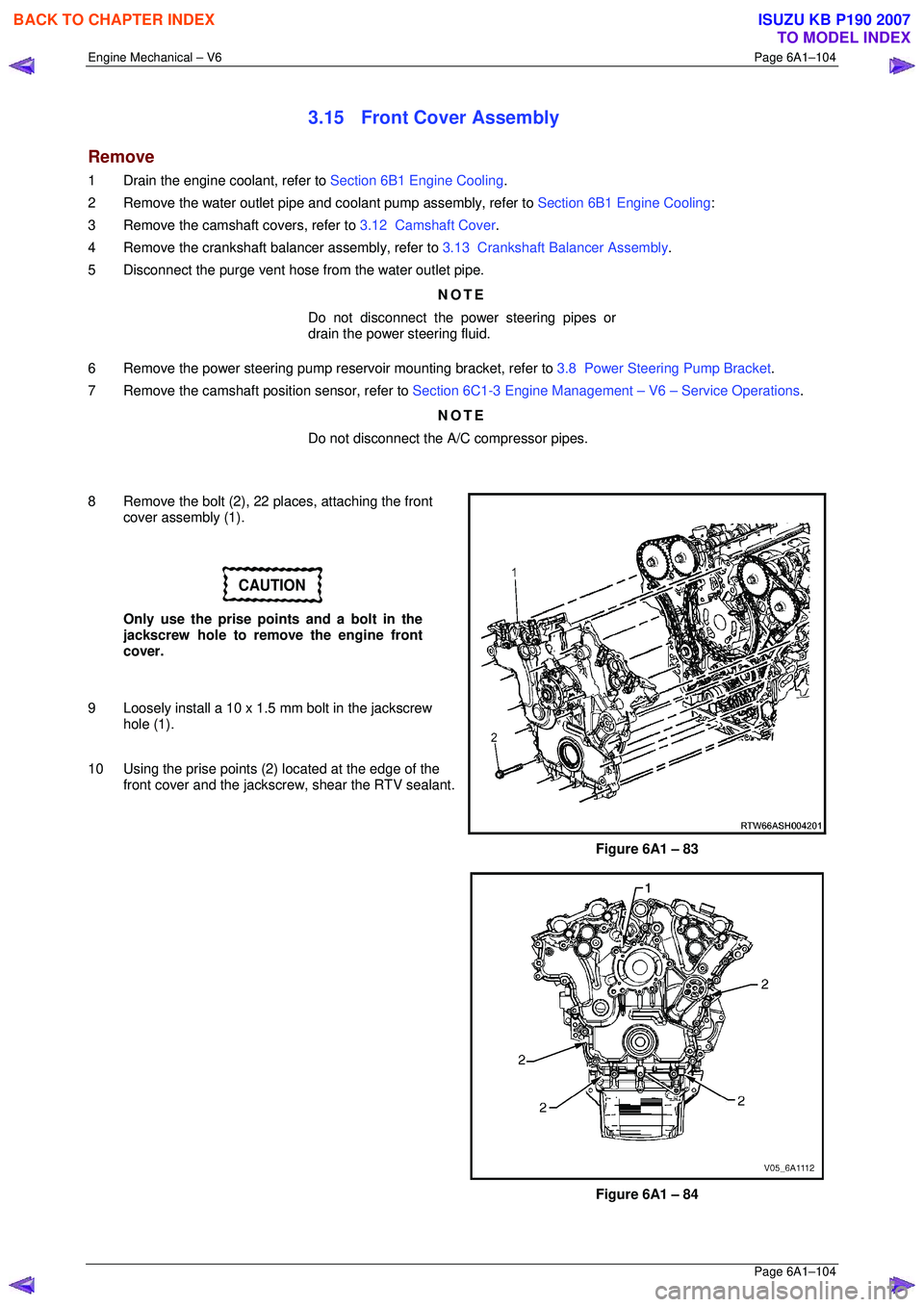
8 Remove the bolt (2), 22 places, attaching the front cover assembly (1).
CAUTION
Only use the prise points and a bolt in the
jackscrew hole to remove the engine front
cover.
9 Loosely install a 10 x 1.5 mm bolt in the jackscrew hole (1).
10 Using the prise points (2) located at the edge of the
front cover and the jackscrew, shear the RTV sealant.
Figure 6A1 – 83
Figure 6A1 – 84
BACK TO CHAPTER INDEX
TO MODEL INDEX
ISUZU KB P190 2007