2007 ISUZU KB P190 ECO mode
[x] Cancel search: ECO modePage 5662 of 6020
SUPPLEMENTAL RESTRAINT SYSTEM 9A-27
5. Remove the passenger air bag assembly from the
vehicle. Refer to “Passenger Air Bag Assembl
y
Removal “.
6. Clear a space on the ground approximately 183 cm (six feet) in diameter where the fixture with
attached air bag assembly is to be placed fo
r
deployment. A paved outdoor location where there
is no activity is preferred. If an outdoor location is
not available, a space on the shop floor where
there is no activity and there is sufficient ventilation
is recommended. Ensure that no loose o
r
flammable objects are within the deployment area.
7. Place the 5-8840-2420-0 on the bench vise. This is necessary to provide sufficient stabilization o
f
the fixture during deployment.
8. Attach the passenger air bag assembly in the 5- 8840-2420-0. The air bag assembly must be
mounted such that the bag will deploy upward.
SECURELY HAND–TIGHTEN ALL FASTENERS
PRIOR TO DEPLOYMENT.
RTW 79ASH000601
9. Stretch the SRS Deployment Harness and pigtail
adapter from the air bag assembly to its full length.
10. Place a power source near the shorted end of the SRS deployment harness. (Recommended
application: 12 volts minimum, 2 amps minimum.
A vehicle battery is suggested.)
11. Connect the air bag assembly to the pigtail adapte
r
on the SRS deployment harness. The SRS
Deployment Harness shall remain shorted and not
be connected to a power source until the air bag is
to be deployed. The air bag assembly will
immediately deploy the air bag when a powe
r
source is connected to it.
NOTE: Ensure that the pigtail adapter is firmly seated
into the air bag assembly connector. Failure to full
y
seat the connectors may leave the shorting bar located
in the air bag assembly connector functioning (shorting
the deployment circuit) and may result in no
deployment of the air bag assembly.
12. Verify that the area around the passenger air bag assembly is clear of all people and loose o
r
flammable objects.
13. Verify that the passenger air bag assembly is firmly and properly in the 5-8840-2420-0.
14. Notify all people in the immediate area of you
r
intention to deploy the passenger air bag
assembly. The deployment will be accompanied
by a substantial noise which may startle the
uninformed.
15. Separate the two banana plugs on the SRS deployment harness.
NOTE: W hen the air bag deploys, the driver air bag
assembly may jump about 30 cm (one foot) vertically.
This is a normal reaction of the driver air bag to the
force of the rapid gas expansion inside the air bag.
NOTE: W hen the air bag deploys, the rapid gas
expansion will create a substantial noise. Notify all
people in the immediate area that you intend to deplo
y
the air bag assembly.
WARNING: THE DEPLOYMENT HARNESS SHALL
REMAIN SHORTED AND NOT BE CONNECTED TO
A POWER SOURCE UNTIL THE AIR BAG IS TO BE
DEPLOYED. THE AIR BAG ASSEMBLY WILL
IMMEDIATELY DEPLOY THE AIR BAG WHEN
A
POWER SOURCE IS CONNECTED TO IT.
CONNECTING THE DEPLOYMENT HARNESS TO
THE POWER SOURCE SHOULD ALWAYS BE THE
LAST STEP IN THE AIR BAG ASSEMBLY
DEPLOYMENT PROCEDURE. FAILURE TO
FOLLOW PROCEDURES IN THE ORDER LISTED
MAY RESULT IN PERSONAL INJURY.
16. Connect the SRS deployment harness wires to the power source to immediately deploy the air bag
assembly. Recommended application : 12 volts
minimum, 2 amps minimum. A vehicle battery is
suggested.
17. Disconnect the SRS deployment harness from the power source.
18. Short the two SRS deployment harness leads together by fully seating one banana plug into the
other.
19. In the unlikely event that the passenger air bag assembly did not deploy after following these
procedures, proceed immediately with Steps 24
through 26. If the passenger air bag assembl
y
deployed as intended, proceed with Steps 20
through 23.
BACK TO CHAPTER INDEX TO MODEL INDEXISUZU KB P190 2007
Page 5665 of 6020
9A-30 SUPPLEMENTAL RESTRAINT SYSTEM
23. Verify that the inside of the vehicle and the area
surrounding the vehicle are clear of all people and
loose or flammable objects.
24. Stretch the driver and passenger deployment harnesses to their full length.
25. Completely cover the windshield area and front door window openings with a drop cloth, blanket o
r
similar item. This reduces the possibility of injury
due to possible fragmentation of the vehicle's
glass or interior.
26. Notify all people in the immediate area that you intend to deploy the air bags. The deployment will
be accompanied by a substantial noise which ma
y
startle the uninformed.
27. Separate the two ends of the driver deployment harness wires.
WARNING: DEPLOYMENT WIRES SHALL REMAIN
SHORTED AND NOT BE CONNECTED TO
A
POWER SOURCE UNTIL THE AIR BAG IS TO BE
DEPLOYED. THE AIR BAG ASSEMBLY WILL
IMMEDIATELY DEPLOY THE AIR BAG WHEN
A
POWER SOURCE IS CONNECTED TO IT.
CONNECTING THE DEPLOYMENT WIRES TO THE
POWER SOURCE SHOULD ALWAYS BE THE
FINAL STEP IN THE AIR BAG ASSEMBLY
DEPLOYMENT PROCEDURE. FAILURE TO
FOLLOW PROCEDURES IN THE ORDER LISTED
COULD RESULT IN PERSONAL INJURY.
NOTE: W hen the air bag deploys, the rapid gas
expansion will create a substantial noise. Notify all
people in the immediate area that you intend to deplo
y
the air bags.
28. Connect the driver deployment harness wires to a power source to immediately deploy the driver ai
r
bag assembly. Recommended application: 12
volts minimum, 2 amps minimum. A vehicle
battery is suggested.
29. Separate the two ends of the passenge
r
deployment harness wires.
WARNING: DEPLOYMENT WIRES SHALL REMAIN
SHORTED AND NOT BE CONNECTED TO
A
POWER SOURCE UNTIL THE AIR BAG IS TO BE
DEPLOYED. THE AIR BAG ASSEMBLY WILL
IMMEDIATELY DEPLOY THE AIR BAG WHEN
A
POWER SOURCE IS CONNECTED TO IT.
CONNECTING THE DEPLOYMENT WIRES TO THE
POWER SOURCE SHOULD ALWAYS BE THE
FINAL STEP IN THE AIR BAG ASSEMBLY
DEPLOYMENT PROCEDURE. FAILURE TO
FOLLOW PROCEDURES IN THE ORDER LISTED
COULD RESULT IN PERSONAL INJURY.
30. Connect the passenger deployment harness wires
to a power source to immediately deploy the
passenger air bag assembly. Recommended
application: 12 volts minimum, 2 amps minimum.
A vehicle battery is suggested.(Driver air bag
assembly) Put on a pair of shop gloves and safet
y
glasses to protect your hands and eyes from
possible irritation and heat when handling the
deployed air bag assembly. After an air bag
assembly has been deployed, the surface of the
air bag may contain a powdery residue. This
powder consists primarily of cornstarch (used to
lubricate the bag as it inflates) and by-products o
f
the chemical reaction. Sodium hydroxide dust
(similar to lye soap) is produced as a by-product o
f
the deployment reaction. The sodium hydroxide
then quickly reacts with atmospheric moisture and
is converted to sodium carbonate and sodium
bicarbonate (baking soda). Therefore, it is unlikel
y
that sodium hydroxide will be present afte
r
deployment (Passenger air bag assembly) The
passenger inflator requires no special precaution
after deployment. 95% of the particulate mission is
potassium chloride (KLC), which is commonly sold
as an edible salt-substitute. Even if water is
applied, post deployment products are relativel
y
pH neutral. Disposing of the inflator by burying it in
a landfill will not produce any hazardous products.
As with any dusty environment, safety goggles,
dust mask and gloves should be worn.
WARNING: SAFETY PRECAUTIONS MUST BE
OBSERVED WHEN HANDLING A DEPLOYED AIR
BAG ASSEMBLY. AFTER DEPLOYMENT, THE
METAL SURFACES OF THE AIR BAG ASSEMBLY
WILL BE VERY HOT. ALLOW THE AIR BAG
ASSEMBLY TO COOL BEFORE HANDLING ANY
METAL PORTION OF IT. DO NOT PLACE THE HOT
DEPLOYED AIR BAG ASSEMBLY NEAR ANY
FLAMMABLE OBJECTS. FAILURE TO FOLLOW
PROCEDURES COULD RESULT IN FIRE OR
PERSONAL INJURY.
After an air bag assembly has been deployed, the
metal canister and surrounding areas of the ai
r
bag assembly will be very hot. Do not touch the
metal areas of the air bag assembly for about 30
minutes after deployment. If the deployed air bag
assembly must be moved before it is cool, wea
r
gloves and handle by the air bag or trim cover.
31. Short the driver deployment harness wires b
y
twisting together one end from each. Repeat this
procedure for the passenger deployment harness.
32. Carefully remove the drop cloth from the vehicle and clean off any fragments or discard the drop
cloth entirely.
33. Disconnect the driver deployment harness and the passenger deployment harness from the vehicle
and discard.
BACK TO CHAPTER INDEX TO MODEL INDEXISUZU KB P190 2007
Page 5667 of 6020
9A-32 SUPPLEMENTAL RESTRAINT SYSTEM
Service Precautions for SRS
Component Service
CAUTION: When fasteners are removed, always
reinstall them at the same location from which
they were removed. If a fastener needs to be
replaced, use the correct part number fastener fo
r
that application. If the correct part number
fastener is not available, a fastener of equal size
and strength (or stronger) may be used. Fasteners
that are not reused, and those requiring a thread
locking compound will be called out. The correct
torque value must be used when installing
fasteners that require it. If the above conditions
are not followed, parts or system damage could
result.
WARNING: WHEN PERFORMING SERVICE ON OR
AROUND SRS COMPONENTS OR SRS WIRING,
FOLLOW THE PROCEDURES LISTED BELOW TO
TEMPORARILY DISABLE THE SRS. FAILURE TO
FOLLOW PROCEDURES COULD RESULT IN
POSSIBLE AIR BAG DEPLOYMENT, PERSONAL
INJURY OR OTHERWISE UNNEEDED SRS
REPAIRS.
The SRS control unit in the Driver–Passenger SRS
can maintain sufficient voltage to cause a deployment
for up to 15 seconds after the ignition switch is turned
“OFF,” the battery is disconnected, or the fuse
powering the SRS control unit is removed.
Many of the service procedures require removal of the
“SRS” fuse, and disconnection of the air bag assembl
y
from the deployment loop to avoid an accidental
deployment. If the air bag assembly is disconnected
from the deployment loop as noted in the “Disabling
the SRS” procedure that follows, service can begin
immediately without waiting for the 15 second time
period to expire.
Disabling The SRS
Removal
Turn the ignition switch to “OFF” and turn the steering
wheel so that the vehicle's wheels are pointing straight
ahead.
1. Remove the SRS fuse “SRS” from the left dash side lower fuse block or disconnect the battery.
2. Disconnect the yellow connector at the base o
f
steering column.
3. Remove the glove box assembly; Refer to “Passenger air bag assembly replacement” in this
section.
4. Disconnect the passenger air bag assembly yello
w
connector behind the glove box assembly.
CAUTION: With the “SRS” fuse removed and the
ignition switch to “ON,” the “SRS” warning lamp
will be “ON.” This is normal operation and does
not indicate an SRS malfunction.
Enabling The SRS
Installation
Turn the ignition switch to “LOCK” and remove the
key.
1. Connect the yellow connector passenger air bag assembly.
2. Install the glove box assembly. Refer to “Passenger Air Bag Assembly Replacement” in
this section.
3. Connect the yellow connector at the base of the steering column.
4. Install the “AIR BAG” fuse “SRS” to the left dash side lower fuse block or connect the battery.
Turn the ignition switch to “ON” and verify that the
“SRS” warning lamp flashes seven times and then
turns to “LOCK”. If it does not operate as described,
perform the “SRS Diagnostic System Check” in this
section.
Handling / Installation / Diagnosis
1. Air bag assembly should not be subjected to
temperatures above 65 °C (150 °F).
2.
Air bag assembly, and SRS control unit should not
be used if they have been dropped from a height
of 100 centimeters (3.28 feet) or more.
3. W hen a SRS control unit is replaced, it must be oriented with the arrow on the SRS control unit
pointing toward the front of the vehicle. It is ver
y
important for the SRS control unit to be located flat
on the mounting surface, parallel to the vehicle
datum line. It is important that the SRS control unit
mounting surface is free of any dirt or other foreign
material.
4. Do not apply power to the SRS unless all components are connected or a diagnostic chart
requests it, as this will set a diagnostic trouble
code.
5. The “SRS Diagnostic System Check” must be the starting point of any SRS diagnostics. The “SRS
Diagnostic System Check” will verify proper “SRS”
warning lamp operation and will lead you to the
correct chart to diagnose any SRS malfunctions.
Bypassing these procedures may result in
extended diagnostic time, incorrect diagnosis, and
incorrect parts replacements.
BACK TO CHAPTER INDEX TO MODEL INDEXISUZU KB P190 2007
Page 5685 of 6020
RESTRAINT CONTROL SYSTEM 9A1-3
Diagnostic Information
CAUTION: When fasteners are removed, always
reinstall them at the same location from which they
were removed. If a fastener needs to be replaced,
use the correct part number fastener for that
application. If the correct part number fastener is
not available, a fastener of equal size and strength
(or stronger) may be used. Fasteners that are not
reused, and those requiring thread locking
compound, will be called out. The correct torque
value must be used when installing fasteners that
require it. If the above conditions are not followed,
parts or system damage could result.
Diagnostic Procedures
WARNING: TO AVOID DEPLOYMENT WHEN
TROUBLESHOOTING THE SRS, DO NOT USE
ELECTRICAL TEST EQUIPMENT SUCH AS
A
BATTERY-POWERED OR AC-POWERED
VOLTMETER, OHMMETER, ETC., OR ANY TYPE OF
ELECTRICAL EQUIPMENT OTHER THAN THAT
SPECIFIED IN THIS MANUAL. DO NOT USE A NON-
POWERED, PROBE-TYPE TESTER.
INSTRUCTIONS IN THIS MANUAL MUST BE
FOLLOWED CAREFULLY, OTHERWISE PERSONAL
INJURY MAY RESULT.
The diagnostic procedures used in this section are
designed to aid in finding and repairing SRS problems.
Outlined below are the steps to find and repair SRS
problems quickly and effectively. Failure to carefull
y
follow these procedures may result in extended
diagnostic time, incorrect diagnosis and incorrect parts
replacement.
1. Perform The “SRS Diagnostic System Check”.
The “SRS Diagnostic System Check” should always be the starting point of any SRS diagnostics. The
“SRS Diagnostic System Check” checks for prope
r
“SRS” warning lamp operation and checks for SRS
trouble codes using both “Flash Code” and “Scan
Tool” Methods.
2. Refer To The Proper Diagnostic Chart As Directed By The “SRS Diagnostic System
Check”.
The “SRS Diagnostic System Check” will lead you to the correct chart to diagnose any SRS problems.
Bypassing these procedures may result in extended
diagnostic time, incorrect diagnosis and incorrect
parts replacement.
3. Repeat The “SRS Diagnostic System Check”
After Any Repair Or Diagnostic Procedures Has
Been Performed.
Performing the “SRS Diagnostic System Check” after all repairs or diagnostic procedures, will assure
that the repair has been made correctly and that no
other conditions exist.
Diagnostic Codes
The SRS control unit maintains a history record of all
diagnostic codes that have been detected since the
SRS codes were last cleared during service.
1. Active Codes - Faults that are presently detected in this ignition cycle. Active codes are stored in RAM
(Random Access Memory).
2. History Codes - All faults detected since the last time the history fault memory was cleared. History codes
are stored in the EEPROM. (Electronically Erasable
Programmable Read only Memory)
How To Read Trouble Codes
All codes (Active and history) can be read (or cleared)
by using a scan tool or equivalent.
If a PDT is not available, have the vehicle serviced by a
HOLDEN dealer.
How To Clear Trouble Codes
Trouble codes can only be cleared by using a Scan
Tool. If a “scan tool” is not available then inform the
owner of the stored codes and suggest that the codes
are cleared upon the next visit to a ISUZU/GM
dealership.
Scan Tool Diagnostics
A scan tool can be used to read current and history
codes and to clear all history codes after a repair is
complete. The scan tool must be updated to
communicate with the SRS through a replaceable
cartridge or a manufacturer's update before it can be
used for SRS diagnostics. To use the scan tool,
connect it to the DLC and turn the ignition switch “ON”.
Then follow the manufacturer's directions fo
r
communication with the SRS. The scan tool reads
serial data from the SRS control unit’s “Serial Data”
output (terminal 21) to the DLC (terminal 2).
BACK TO CHAPTER INDEX TO MODEL INDEX
ISUZU KB P190 2007
Page 5687 of 6020
RESTRAINT CONTROL SYSTEM 9A1-5
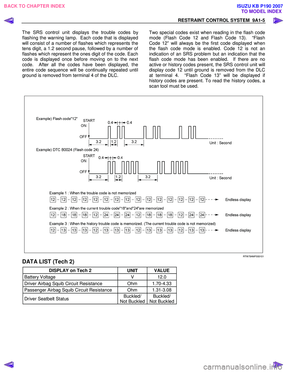
The SRS control unit displays the trouble codes b
y
flashing the warning lamp. Each code that is displayed
will consist of a number of flashes which represents the
tens digit, a 1.2 second pause, followed by a number o
f
flashes which represent the ones digit of the code. Each
code is displayed once before moving on to the next
code. After all the codes have been displayed, the
entire code sequence will be continually repeated until
ground is removed from terminal 4 of the DLC.
Two special codes exist when reading in the flash code
mode (Flash Code 12 and Flash Code 13). “Flash
Code 12” will always be the first code displayed when
the flash code mode is enabled. Code 12 is not an
indication of an SRS problem but an indication that the
flash code mode has been enabled. If there are no
active or history codes present, the SRS control unit will
display code 12 until ground is removed from the DLC
at terminal 4. “Flash Code 13” will be displayed i
f
history codes are present. To read the history codes, a
scan tool must be used.
RTW 79AMF000101
DATA LIST (Tech 2)
DISPLAY on Tech 2 UNIT VALUE
Battery Voltage
V 12.0
Driver Airbag Squib Circuit Resistance Ohm 1.70-4.33
Passenger Airbag Squib Circuit Resistance Ohm 1.31-3.08
Driver Seatbelt Status Buckled/
Not Buckled Buckled/
Not Buckled
BACK TO CHAPTER INDEX
TO MODEL INDEX
ISUZU KB P190 2007
Page 5690 of 6020
9A1-8 RESTRAINT CONTROL SYSTEM
Circuit Description
W hen the ignition switch is first turned “ON”, “Ignition 1”
voltage is applied from the “SRS” fuse to the SRS
control unit at the “Ignition 1” input terminals “1”. The
SRS control unit responds by flashing the “SRS”
warning lamp seven times, while performing tests on
the SRS.
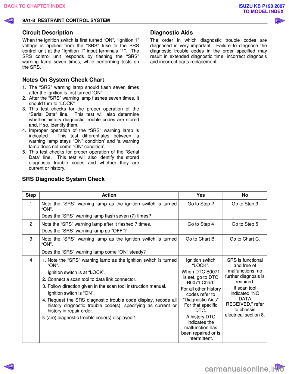
Notes On System Check Chart
1. The “SRS” warning lamp should flash seven times after the ignition is first turned “ON”.
2.
After the “SRS” warning lamp flashes seven times, it
should turn to “LOCK”
3. This test checks for the proper operation of the “Serial Data” line. This test will also determine
whether history diagnostic trouble codes are stored
and, if so, identify them.
4. Improper operation of the “SRS” warning lamp is indicated. This test differentiates between ‘a
warning lamp stays “ON” condition’ and ‘a warning
lamp does not come “ON” condition’.
5. This test checks for proper operation of the “Serial Data” line. This test will also identify the stored
diagnostic trouble codes and whether they are
current or history.
Diagnostic Aids
The order in which diagnostic trouble codes are
diagnosed is very important. Failure to diagnose the
diagnostic trouble codes in the order specified ma
y
result in extended diagnostic time, incorrect diagnosis
and incorrect parts replacement.
SRS Diagnostic System Check
Step Action Yes No
1 Note the “SRS” warning lamp as the ignition switch is turned
“ON”.
Does the “SRS” warning lamp flash seven (7) times? Go to Step 2 Go to Step 3
2 Note the “SRS” warning lamp after it flashed 7 times.
Does the “SRS” warning lamp go “OFF”? Go to Step 4 Go to Step 5
3 Note the “SRS” warning lamp as the ignition switch is turned
“ON”.
Does the “SRS” warning lamp come “ON” steady? Go to Chart B. Go to Chart C.
4
1. Note the “SRS” warning lamp as the ignition switch is turned
“ON”.
Ignition switch is at “LOCK”.
2. Connect a scan tool to data link connector.
3. Follow direction given in the scan tool instruction manual.
Ignition switch is “ON”.
4. Request the SRS diagnostic trouble code display, recode all
history diagnostic trouble code(s), specifying as current or
history in repair order.
Is (are) diagnostic trouble code(s) displayed?
Ignition switch
“LOCK”.
W hen DTC B0071 is set, go to DTC B0071 Chart.
For all other history codes refer to
“Diagnostic Aids” For that specific DTC.
A history DTC indicates the
malfunction has
been repaired or is intermittent. SRS is functional
and free of
malfunctions, no
further diagnosis is required.
If scan tool
indicated “NO DATA
RECEIVED,” refer to chassis
electrical section 8.
BACK TO CHAPTER INDEX TO MODEL INDEX
ISUZU KB P190 2007
Page 5691 of 6020
RESTRAINT CONTROL SYSTEM 9A1-9
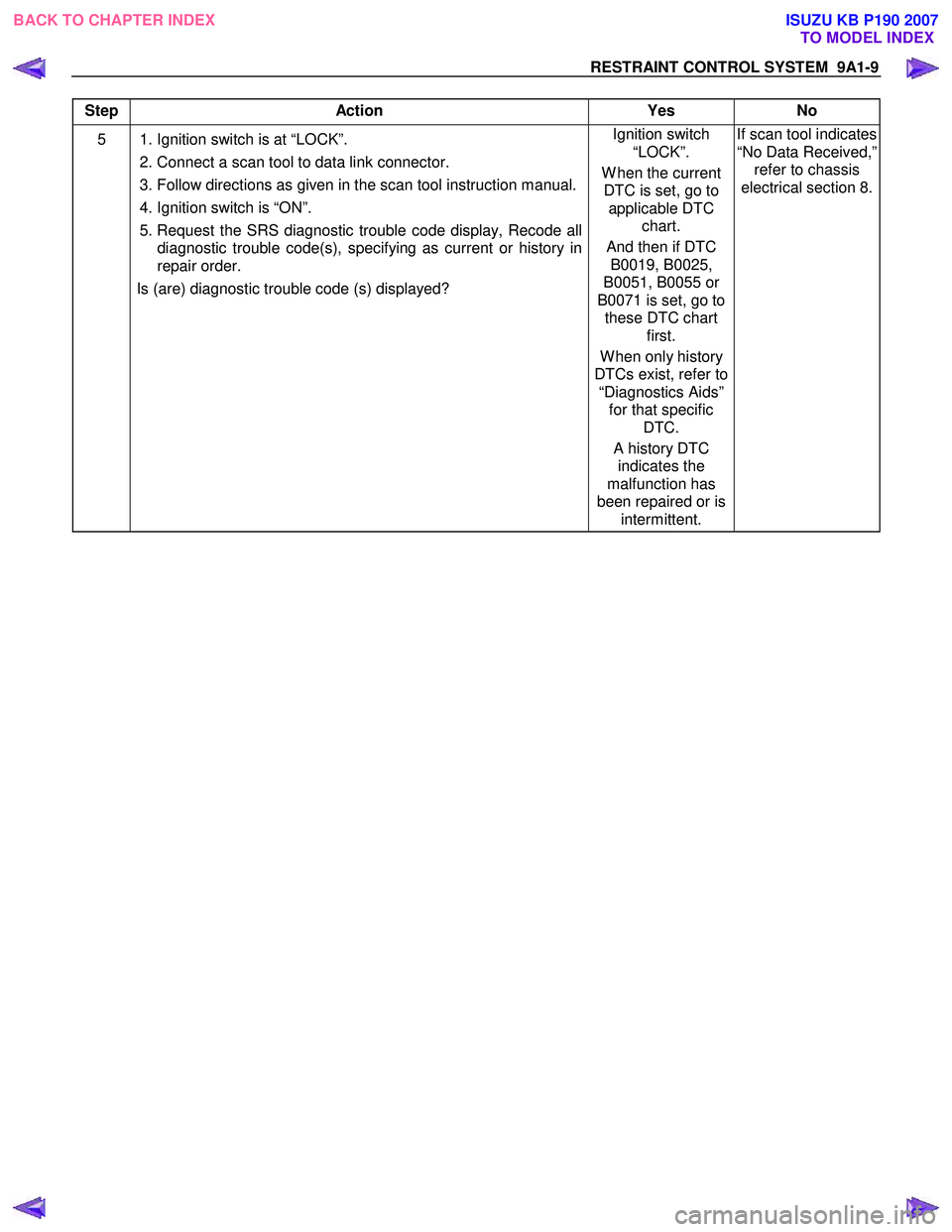
Step Action Yes No
5 1. Ignition switch is at “LOCK”.
2. Connect a scan tool to data link connector.
3. Follow directions as given in the scan tool instruction manual.
4. Ignition switch is “ON”.
5. Request the SRS diagnostic trouble code display, Recode all diagnostic trouble code(s), specifying as current or history in
repair order.
Is (are) diagnostic trouble code (s) displayed? Ignition switch
“LOCK”.
W hen the current DTC is set, go to applicable DTC chart.
And then if DTC B0019, B0025,
B0051, B0055 or
B0071 is set, go to these DTC chart first.
W hen only history
DTCs exist, refer to “Diagnostics Aids” for that specific DTC.
A history DTC indicates the
malfunction has
been repaired or is intermittent. If scan tool indicates
“No Data Received,” refer to chassis
electrical section 8.
BACK TO CHAPTER INDEX TO MODEL INDEX
ISUZU KB P190 2007
Page 5692 of 6020
9A1-10 RESTRAINT CONTROL SYSTEM
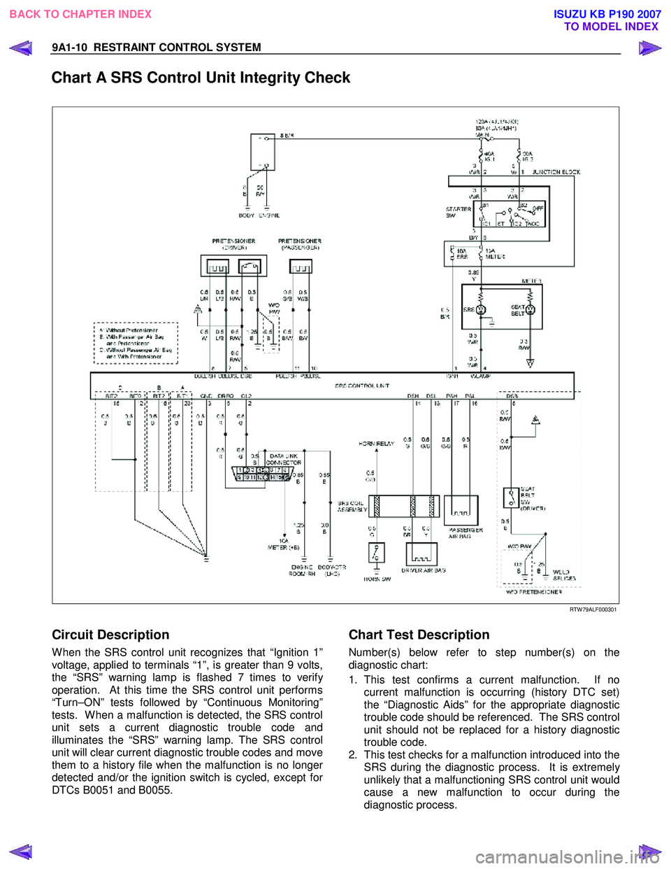
Chart A SRS Control Unit Integrity Check
RTW 79ALF000301
Circuit Description
W hen the SRS control unit recognizes that “Ignition 1”
voltage, applied to terminals “1”, is greater than 9 volts,
the “SRS” warning lamp is flashed 7 times to verif
y
operation. At this time the SRS control unit performs
“Turn–ON” tests followed by “Continuous Monitoring”
tests. W hen a malfunction is detected, the SRS control
unit sets a current diagnostic trouble code and
illuminates the “SRS” warning lamp. The SRS control
unit will clear current diagnostic trouble codes and move
them to a history file when the malfunction is no longe
r
detected and/or the ignition switch is cycled, except for
DTCs B0051 and B0055.
Chart Test Description
Number(s) below refer to step number(s) on the
diagnostic chart:
1. This test confirms a current malfunction. If no current malfunction is occurring (history DTC set)
the “Diagnostic Aids” for the appropriate diagnostic
trouble code should be referenced. The SRS control
unit should not be replaced for a history diagnostic
trouble code.
2. This test checks for a malfunction introduced into the SRS during the diagnostic process. It is extremel
y
unlikely that a malfunctioning SRS control unit would
cause a new malfunction to occur during the
diagnostic process.
BACK TO CHAPTER INDEX TO MODEL INDEX
ISUZU KB P190 2007