Page 4957 of 6020
ELECTRICAL-BODY AND CHASSIS 8A-19
Battery-1
BATTERY
Inspection
1. Check the battery terminals 1 for corrosion.
2. Check the battery cables
2 for looseness.
3. Check the battery case
3 for cracks and other damage.
4. Check the battery electrolyte level.
Battery-2
Battery Replacement
1. Disconnect the battery ground cable 1.
2. Disconnect the battery positive cable
2.
3. Remove the battery clamp
3.
4. Remove the battery
Caution:
It is important that the battery ground cable be removed
first.
Removing the battery positive cable first can result in a
short circuit.
Jump Starting the Engine with a Booster Battery
The following description assumes that you are using a booster
battery mounted on a second vehicle.
The listed steps (with some minor modifications) are also
applicable if you are using a naked booster battery or special
battery charging equipment.
BACK TO CHAPTER INDEX TO MODEL INDEXISUZU KB P190 2007
Page 5171 of 6020
ELECTRICAL-BODY AND CHASSIS 8A-233
HORN
1. Both sides of horn do not sound
Checkpoint Trouble Cause Countermeasure
Repair the grounding point
Poor ground contact
NG
Horn relay
Grounding point
Reinstall or replace fuse No.
EB15 (10A)
Fuse No EB15 (10A, Relay
and fuse box)
Poor fuse contact or blown
fuse
NG
OK
OK
Reinstall or replace the horn
relay
Poor relay contact or faulty
horn relay
NG
Voltage between connector
3
X3 - ground or 1 X3
- ground (Should be battery
v oltage present) OK
Repair open circuit or
reconnect the connector
Open circuit or poor connector
contact between fuse No.
EB15 (10A) and horn relay
NG
Remov e steering pad and
steering wheel
OK
Horn switch continuity
OK
Repair or replace the horn
switch
Poor switch point contact or
faulty switch
NG
Continuity between
5
X3 - 10 B60
2
X3 - 1 C20 (1 C21 )
OK
Repair open circuit or
connector contact
Open circuit or poor connector
contact
NG
BACK TO CHAPTER INDEX
TO MODEL INDEXISUZU KB P190 2007
Page 5172 of 6020
8A-234 ELECTRICAL-BODY AND CHASSIS
2. One side of horn does not blow
Checkpoint Trouble Cause Countermeasure
Repair open circuit or
reconnect the connector
Open circuit or poor connector
contact
NG Voltage between 1
C20
(1
C21 ) - ground with
horn switch depressed
(Should be battery voltage
present)
Replace the horn assembly
Horn continuity between
connectors
Faulty horn assembly
NG
OK
3. Insufficient horn volume
Clfean and/or remove the
foreign materialStain foreign material in the
horn
NGHorn
Recharge or replace the
batteryBattery conditionDischarged battery
NG
OK
BACK TO CHAPTER INDEX
TO MODEL INDEXISUZU KB P190 2007
Page 5218 of 6020

8A-280 ELECTRICAL-BODY AND CHASSIS
High Speed Inspection
1. Clamp the wiper motor in a vise.
The moving parts must be clear of the vise.
2. Connect the connector terminals to the battery.
Refer to the illustration.
3. Check the wiper motor high speed operation.
Auto-Stop Inspection
1. Clamp the wiper motor in a vise.
The moving parts must be clear of the vise.
2. Connect the connector terminals to the battery.
Refer to the illustration.
3. Check the wiper motor low speed operation.
4. Disconnect the positive battery terminal.
This will stop the motor.
5. Connect the connector terminals No. 3 and No. 6 with a
lead wire.
Refer to the illustration.
6. Reconnect the positive battery terminal to connecto
r
terminal No. 4.
This will restart the motor.
Refer to the illustration.
7. Check the auto-stop operation.
Washer Motor Inspection
1. Fill the washer tank with washing solution.
2. Disconnect the motor connector.
3. Apply battery voltage to the washer motor connector.
4. Check the washer motor operation.
BACK TO CHAPTER INDEX TO MODEL INDEXISUZU KB P190 2007
Page 5300 of 6020

8A-362 ELECTRICAL-BODY AND CHASSIS
Tachometer Off-Vehicle Inspection
Remove the tachometer from the meter assembly and
measure the resistance value and the current consumption
between each terminal.
SELF DIAGNOSTIC FUNCTION
Check that the speedometer, tachometer, fuel gauge, and
temperature gauge operate properly.
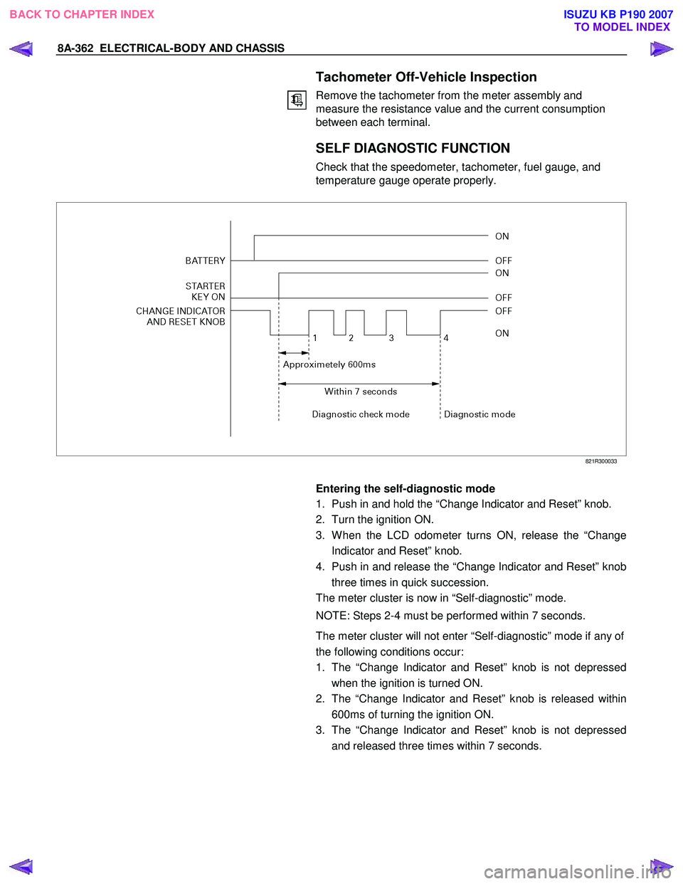
821R300033
Entering the self-diagnostic mode
1. Push in and hold the “Change Indicator and Reset” knob.
2. Turn the ignition ON.
3. W hen the LCD odometer turns ON, release the “Change Indicator and Reset” knob.
4. Push in and release the “Change Indicator and Reset” knob three times in quick succession.
The meter cluster is now in “Self-diagnostic” mode.
NOTE: Steps 2-4 must be performed within 7 seconds.
The meter cluster will not enter “Self-diagnostic” mode if any of
the following conditions occur:
1. The “Change Indicator and Reset” knob is not depressed when the ignition is turned ON.
2. The “Change Indicator and Reset” knob is released within 600ms of turning the ignition ON.
3. The “Change Indicator and Reset” knob is not depressed and released three times within 7 seconds.
BACK TO CHAPTER INDEX TO MODEL INDEXISUZU KB P190 2007
Page 5351 of 6020
ELECTRICAL-BODY AND CHASSIS 8A-413
Harness side
D20 D5
2. Switch Side Connector Circuit
Remove the switch connector, and check continuity and voltage between the switch connector terminals.
(Connect the (+) terminal of the battery to 1
D5and the
(-) terminal to 3
D5.)
3
D5 - 4 D5.................. Continuity
3 D5 - 5 D5.................. Continuity
(Then, ground 3 D5.)
4
D5.......... Current flow for approx. 1 second
(Disconnect the ground of 14 D20 , and ground 13 D20.)
5
D5.......... Current flow for approx. 1 second
Harness side
D5
3. Door Lock Operation Test
After confirming that there is continuity between the switch
harness side connector terminals 4
D5 and 5 D5,
apply the battery voltage to each of the terminals to conduct
the operation test.
W hen the door lock will not operate, check the door lock actuator for any trouble.
Connecting terminals
5 (L) 4 (L/R)
+ - Unlock
- + Lock
Operation
BACK TO CHAPTER INDEX TO MODEL INDEXISUZU KB P190 2007
Page 5400 of 6020

8A-462 ELECTRICAL-BODY AND CHASSIS
TROUBLESHOOTING
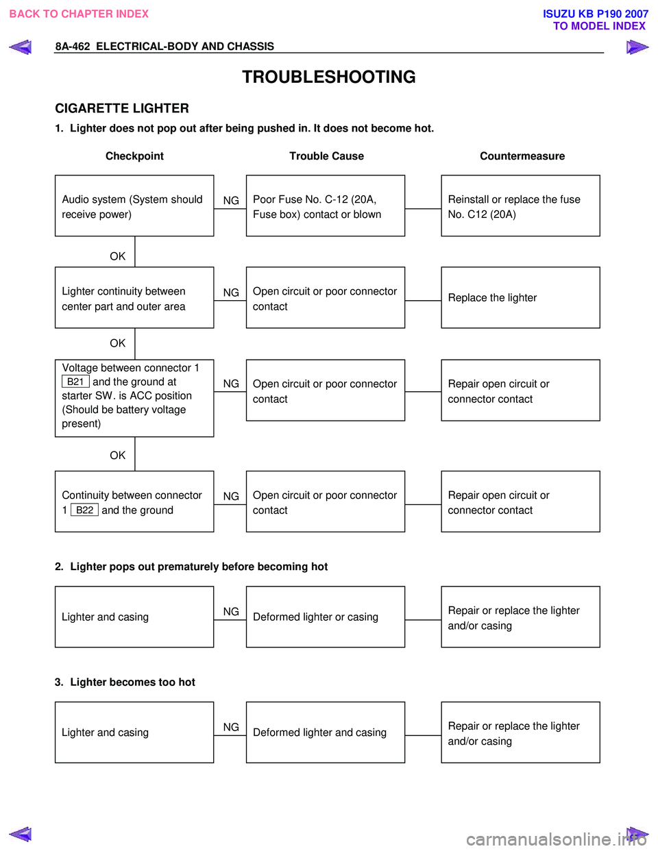
CIGARETTE LIGHTER
1. Lighter does not pop out after being pushed in. It does not become hot.
Checkpoint Trouble Cause Countermeasure
Reinstall or replace the fuse
No. C12 (20A)
Poor Fuse No. C-12 (20A,
Fuse box) contact or blown
NG
Replace the lighter
Lighter continuity between
center part and outer area
Open circuit or poor connector
contact
Repair open circuit or
connector contact
Voltage between connector 1
B21 and the ground at
starter SW . is ACC position
(Should be battery voltage
present)
Open circuit or poor connector
contact
NG
NG
OK
OK
OK
Audio system (System should
receive power)
Repair open circuit or
connector contact
Open circuit or poor connector
contact
NG
Continuity between connector
1
B22 and the ground
2. Lighter pops out prematurely before becoming hot
Repair or replace the lighter
and/or casingDeformed lighter or casing
NGLighter and casing
3. Lighter becomes too hot
Repair or replace the lighter
and/or casingDeformed lighter and casing
NGLighter and casing
BACK TO CHAPTER INDEX
TO MODEL INDEXISUZU KB P190 2007
Page 5427 of 6020

ELECTRICAL-BODY AND CHASSIS 8A-489
INSPECTION AND REPAIR
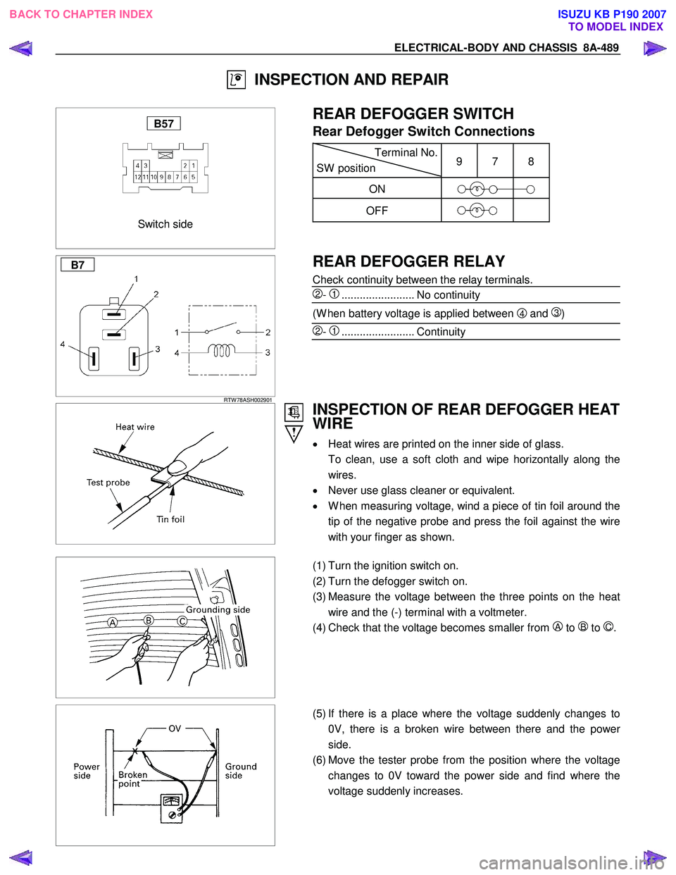
Switch side
B57
REAR DEFOGGER SWITCH
Rear Defogger Switch Connections
Terminal No.
SW position 9 7 8
ON
OFF
B7
RTW 78ASH002901
REAR DEFOGGER RELAY
Check continuity between the relay terminals.
2- 1........................ No continuity
(W hen battery voltage is applied between 4 and 3)
2- 1........................ Continuity
INSPECTION OF REAR DEFOGGER HEAT
WIRE
• Heat wires are printed on the inner side of glass.
To clean, use a soft cloth and wipe horizontally along the wires.
• Never use glass cleaner or equivalent.
• W hen measuring voltage, wind a piece of tin foil around the
tip of the negative probe and press the foil against the wire
with your finger as shown.
(1) Turn the ignition switch on.
(2) Turn the defogger switch on.
(3) Measure the voltage between the three points on the heat wire and the (-) terminal with a voltmeter.
(4) Check that the voltage becomes smaller from
A to B to C.
(5) If there is a place where the voltage suddenly changes to
0V, there is a broken wire between there and the powe
r
side.
(6) Move the tester probe from the position where the voltage changes to 0V toward the power side and find where the
voltage suddenly increases.
BACK TO CHAPTER INDEX TO MODEL INDEXISUZU KB P190 2007