Page 4679 of 6020
MANUAL TRANSMISSION 7B1-73
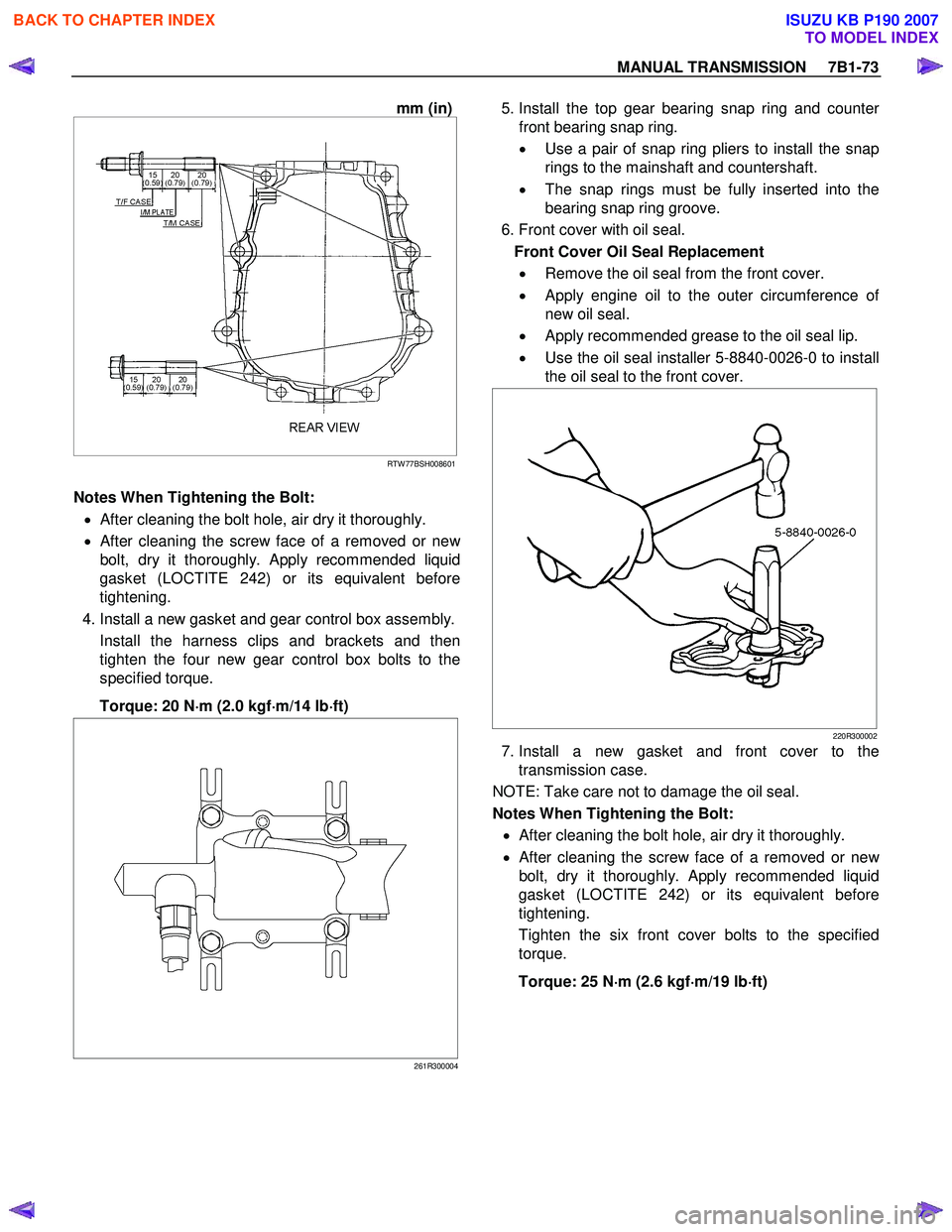
mm (in)
RTW 77BSH008601
Notes When Tightening the Bolt:
• After cleaning the bolt hole, air dry it thoroughly.
•
After cleaning the screw face of a removed or new
bolt, dry it thoroughly. Apply recommended liquid
gasket (LOCTITE 242) or its equivalent before
tightening.
4. Install a new gasket and gear control box assembly. Install the harness clips and brackets and then
tighten the four new gear control box bolts to the
specified torque.
Torque: 20 N ⋅
⋅⋅
⋅
m (2.0 kgf ⋅
⋅⋅
⋅
m/14 lb ⋅
⋅⋅
⋅
ft)
261R300004
5. Install the top gear bearing snap ring and counte
r
front bearing snap ring.
• Use a pair of snap ring pliers to install the snap
rings to the mainshaft and countershaft.
• The snap rings must be fully inserted into the
bearing snap ring groove.
6. Front cover with oil seal. Front Cover Oil Seal Replacement • Remove the oil seal from the front cover.
• Apply engine oil to the outer circumference o
f
new oil seal.
• Apply recommended grease to the oil seal lip.
• Use the oil seal installer 5-8840-0026-0 to install
the oil seal to the front cover.
220R300002
7. Install a new gasket and front cover to the transmission case.
NOTE: Take care not to damage the oil seal.
Notes When Tightening the Bolt:
• After cleaning the bolt hole, air dry it thoroughly.
•
After cleaning the screw face of a removed or new
bolt, dry it thoroughly.
Apply recommended liquid
gasket (LOCTITE 242) or its equivalent before
tightening.
Tighten the six front cover bolts to the specified
torque.
Torque: 25 N ⋅
⋅⋅
⋅
m (2.6 kgf ⋅
⋅⋅
⋅
m/19 lb ⋅
⋅⋅
⋅
ft)
BACK TO CHAPTER INDEX
TO MODEL INDEX
ISUZU KB P190 2007
Page 4689 of 6020
MANUAL TRANSMISSION 7B1-83
2. Install the bearing snap ring.
3.
Apply recommended thread locking agents
(LOCTITE 242) or equivalent to each of the bearing
plate screw threads.
Install the bearing plate and screw.
Tighten the screws to the specified torque by using
torx bit wrench (T- 45) 5-8840-0047-0.
Torque: 15 N ⋅
⋅⋅
⋅
m (1.5 kgf ⋅
⋅⋅
⋅
m/11 lb ⋅
⋅⋅
⋅
ft)
220RW 137
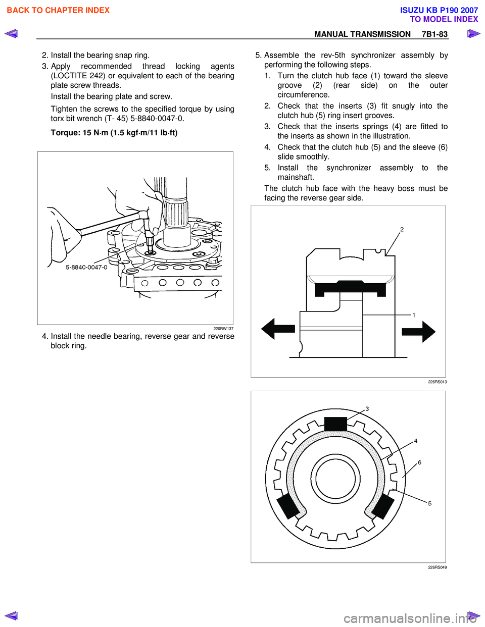
4. Install the needle bearing, reverse gear and reverse block ring. 5. Assemble the rev-5th synchronizer assembly b
y
performing the following steps.
1. Turn the clutch hub face (1) toward the sleeve groove (2) (rear side) on the oute
r
circumference.
2. Check that the inserts (3) fit snugly into the clutch hub (5) ring insert grooves.
3. Check that the inserts springs (4) are fitted to the inserts as shown in the illustration.
4. Check that the clutch hub (5) and the sleeve (6) slide smoothly.
5. Install the synchronizer assembly to the mainshaft.
The clutch hub face with the heavy boss must be
facing the reverse gear side.
226RS013
226RS049
BACK TO CHAPTER INDEX
TO MODEL INDEX
ISUZU KB P190 2007
Page 4748 of 6020
Manual Transmission (MUX) 7B1-29
42. In order to protect the front oil seal lip, wrap a tapearound the spline portion of the input shaft.
43. Install the intermediate plate assembly with gear (1) to the front case.
• Apply recommended liquid gasket (LOCTITE FMD-127 or equivalent) with the width of 3 to 5
mm to the area marked in the figure below. 44. Install the magnet (1).
45. Remove the straight plug (1) from the rear case.
46. Install the rear case assembly.
RTW77BSH007601
1
4
3
2
RTW77BSH005801
RTW77BSH007501
1
RTW77BSH008201
1
RTW77BSH0063011
BACK TO CHAPTER INDEX
TO MODEL INDEX
ISUZU KB P190 2007
Page 4749 of 6020
7B1-30 Manual Transmission (MUX)
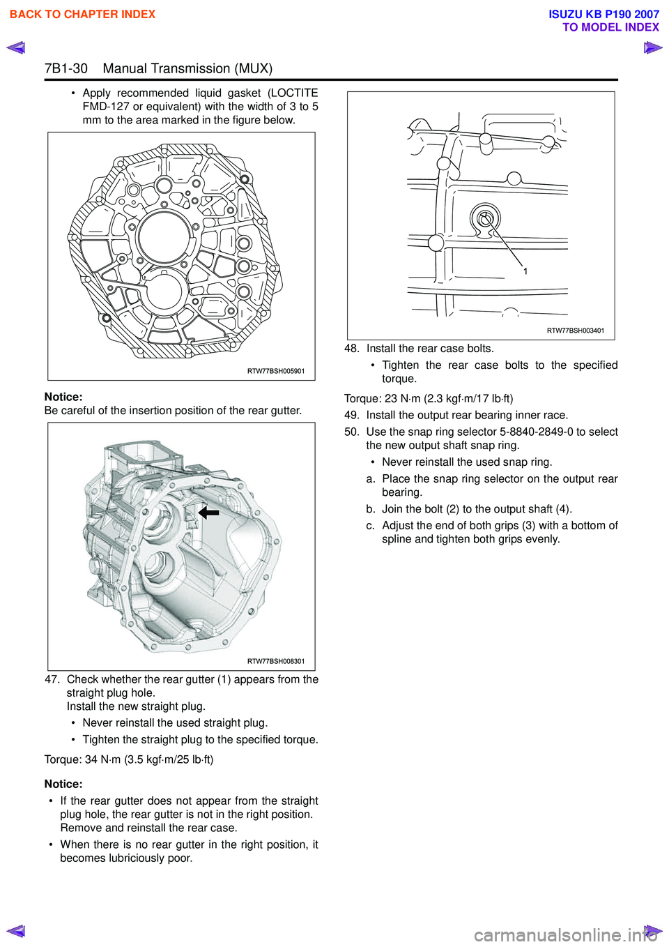
• Apply recommended liquid gasket (LOCTITEFMD-127 or equivalent) with the width of 3 to 5
mm to the area marked in the figure below.
Notice:
Be careful of the insertion position of the rear gutter.
47. Check whether the rear gutter (1) appears from the straight plug hole.
Install the new straight plug.
• Never reinstall the used straight plug.
• Tighten the straight plug to the specified torque.
Torque: 34 N ⋅m (3.5 kgf ⋅m/25 lb ⋅ft)
Notice: • If the rear gutter does not appear from the straight plug hole, the rear gutter is not in the right position.
Remove and reinstall the rear case.
• When there is no rear gutter in the right position, it becomes lubriciously poor. 48. Install the rear case bolts.
• Tighten the rear case bolts to the specifiedtorque.
Torque: 23 N ⋅m (2.3 kgf ⋅m/17 lb ⋅ft)
49. Install the output rear bearing inner race.
50. Use the snap ring selector 5-8840-2849-0 to select the new output shaft snap ring.
• Never reinstall the used snap ring.
a. Place the snap ring selector on the output rear bearing.
b. Join the bolt (2) to the output shaft (4).
c. Adjust the end of both grips (3) with a bottom of spline and tighten both grips evenly.
RTW77BSH005901
RTW77BSH008301
RTW77BSH003401
1
BACK TO CHAPTER INDEX
TO MODEL INDEX
ISUZU KB P190 2007
Page 4751 of 6020
7B1-32 Manual Transmission (MUX)
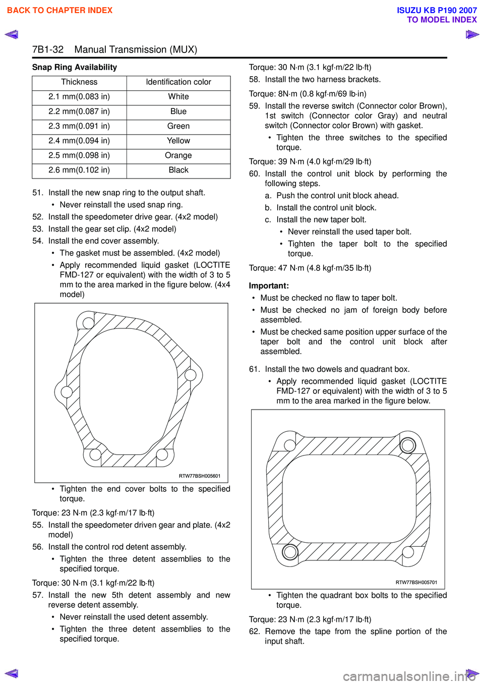
Snap Ring Availability51. Install the new snap ring to the output shaft. • Never reinstall the used snap ring.
52. Install the speedometer drive gear. (4x2 model)
53. Install the gear set clip. (4x2 model)
54. Install the end cover assembly.
• The gasket must be assembled. (4x2 model)
• Apply recommended liquid gasket (LOCTITE FMD-127 or equivalent) with the width of 3 to 5
mm to the area marked in the figure below. (4x4
model)
• Tighten the end cover bolts to the specified torque.
Torque: 23 N ⋅m (2.3 kgf ⋅m/17 lb ⋅ft)
55. Install the speedometer driven gear and plate. (4x2 model)
56. Install the control rod detent assembly.
• Tighten the three detent assemblies to thespecified torque.
Torque: 30 N ⋅m (3.1 kgf ⋅m/22 lb ⋅ft)
57. Install the new 5th detent assembly and new reverse detent assembly.
• Never reinstall the used detent assembly.
• Tighten the three detent assemblies to the specified torque. Torque: 30 N
⋅m (3.1 kgf ⋅m/22 lb ⋅ft)
58. Install the two harness brackets.
Torque: 8N ⋅m (0.8 kgf ⋅m/69 lb ⋅in)
59. Install the reverse switch (Connector color Brown), 1st switch (Connector color Gray) and neutral
switch (Connector color Brown) with gasket.
• Tighten the three switches to the specified torque.
Torque: 39 N ⋅m (4.0 kgf ⋅m/29 lb ⋅ft)
60. Install the control unit block by performing the following steps.
a. Push the control unit block ahead.
b. Install the control unit block.
c. Install the new taper bolt.
• Never reinstall the used taper bolt.
• Tighten the taper bolt to the specified torque.
Torque: 47 N ⋅m (4.8 kgf ⋅m/35 lb ⋅ft)
Important: • Must be checked no flaw to taper bolt.
• Must be checked no jam of foreign body before assembled.
• Must be checked same position upper surface of the taper bolt and the control unit block after
assembled.
61. Install the two dowels and quadrant box. • Apply recommended liquid gasket (LOCTITEFMD-127 or equivalent) with the width of 3 to 5
mm to the area marked in the figure below.
• Tighten the quadrant box bolts to the specified torque.
Torque: 23 N ⋅m (2.3 kgf ⋅m/17 lb ⋅ft)
62. Remove the tape from the spline portion of the input shaft.
Thickness
Identification color
2.1 mm(0.083 in) White
2.2 mm(0.087 in) Blue
2.3 mm(0.091 in) Green
2.4 mm(0.094 in) Yellow
2.5 mm(0.098 in) Orange
2.6 mm(0.102 in) Black
RTW77BSH005601
RTW77BSH005701
BACK TO CHAPTER INDEX
TO MODEL INDEX
ISUZU KB P190 2007
Page 4799 of 6020
CLUTCH 7C-21
AIR BLEEDING
Bleed air from clutch operating cylinder according to the
following procedure.
Carefully monitor fluid level at master cylinder during bleeding
operation.
1. Set the parking brake.
2. Top up reservoir with recommended brake fluid.
3. Connect a transparent vinyl tube to air bleeder valve.
4. Fully depress clutch pedal several times.
RUW 57CSH000201
5. W ith clutch pedal depressed, open bleeder valve to release
air.
6. Close bleeder valve.
7. Repeat steps 5 through 6 above until brake fluid flows from air bleeder valve without air bubbles.
8. Bleed air from clutch damper according to the above procedure.
9. Repeat the above bleeding procedure until the air completely removed.
BACK TO CHAPTER INDEX
TO MODEL INDEX
ISUZU KB P190 2007
Page 4805 of 6020
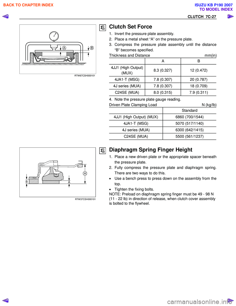
CLUTCH 7C-27
RTW 67CSH000101
Clutch Set Force
1. Invert the pressure plate assembly.
2. Place a metal sheet “A” on the pressure plate.
3. Compress the pressure plate assembly until the distance “B” becomes specified.
Thickness and Distance mm(in
)
A B
4JJ1 (High Output)
(MUX) 8.3 (0.327) 12 (0.472)
4JA1-T (MSG) 7.8 (0.307) 20 (0.787)
4J series (MUA) 7.8 (0.307) 18 (0.709)
C24SE (MUA) 8.0 (0.315) 7.9 (0.311)
4. Note the pressure plate gauge reading.
Driven Plate Clamping Load N (kg/Ib)
Standard
4JJ1 (High Output) (MUX) 6860 (700/1544)
4JA1-T (MSG) 5070 (517/1140)
4J series (MUA) 6300 (642/1415)
C24SE (MUA) 5500 (561/1237)
RTW 37CSH000101
Diaphragm Spring Finger Height
1. Place a new driven plate or the appropriate spacer beneath
the pressure plate.
2. Fully compress the pressure plate and diaphragm spring. There are two ways to do this.
• Use a bench press to press down on the assembly from the
top.
• Tighten the fixing bolts.
NOTE: Preload on diaphragm spring finger must be 49 - 98 N
(11 - 22 lb) in direction of release, when clutch cover assembly
is bolted to the flywheel.
BACK TO CHAPTER INDEX
TO MODEL INDEX
ISUZU KB P190 2007
Page 4833 of 6020
TRANSFER CASE 7D-3
General Description
RTW 57ALF000301
The transfer case is used to provide a means of
providing power flow to the front axle. The transfer case
also provides a means of disconnecting the front axle,
providing better fuel economy and quieter operation
when the vehicle is driven on improved roads where fou
r
wheel drive is not required. In addition, the transfer case
provides an additional gear reduction when placed in lo
w
range, which is useful when difficult off-road conditions
are encountered.
Use the 4W D switch on the center cluster panel to select
the drive range. The 4W D indicator lamp will be lit when
4W D is selected.
BACK TO CHAPTER INDEX
TO MODEL INDEX
ISUZU KB P190 2007