2007 ISUZU KB P190 ECO mode
[x] Cancel search: ECO modePage 4375 of 6020
TRANSMISSION CONTROL SYSTEM (JR405E) 7A2-91
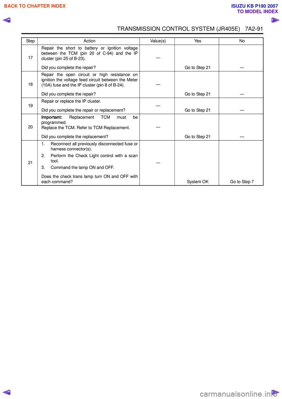
17Repair the short to battery or ignition voltage
between the TCM (pin 20 of C-94) and the IP
cluster (pin 25 of B-23).
Did you complete the repair? —
Go to Step 21 —
18 Repair the open circuit or high resistance on
ignition the voltage feed circuit between the Meter
(10A) fuse and the IP cluster (pin 8 of B-24).
Did you complete the repair? —
Go to Step 21 —
19 Repair or replace the IP cluster.
Did you complete the repair or replacement? —
Go to Step 21 —
20 Important:
Replacement TCM must be
programmed.
Replace the TCM. Refer to TCM Replacement.
Did you complete the replacement? —
Go to Step 21 —
21 1. Reconnect all previously disconnected fuse or
harness connector(s).
2. Perform the Check Light control with a scan tool.
3. Command the lamp ON and OFF.
Does the check trans lamp turn ON and OFF with
each command? —
System OK Go to Step 7
Step
Action Value(s)Yes No
BACK TO CHAPTER INDEX
TO MODEL INDEX
ISUZU KB P190 2007
Page 4378 of 6020
7A2-94 TRANSMISSION CONTROL SYSTEM (JR405E)
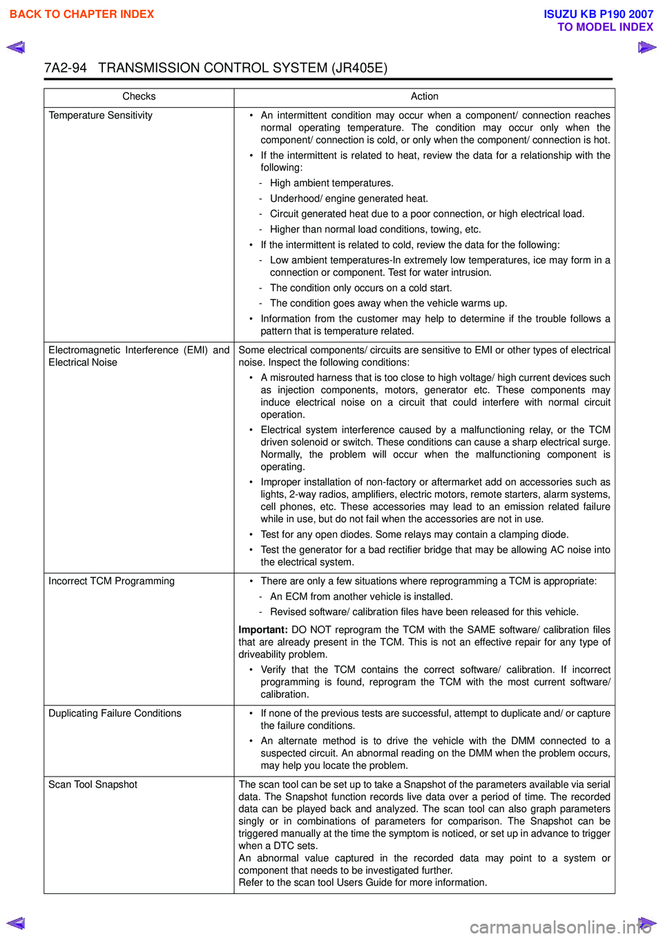
Temperature Sensitivity• An intermittent condition may occur when a component/ connection reaches
normal operating temperature. The condition may occur only when the
component/ connection is cold, or only when the component/ connection is hot.
• If the intermittent is related to heat, review the data for a relationship with the following:
- High ambient temperatures.
- Underhood/ engine generated heat.
- Circuit generated heat due to a poor connection, or high electrical load.
- Higher than normal load conditions, towing, etc.
• If the intermittent is related to cold, review the data for the following: - Low ambient temperatures-In extremely low temperatures, ice may form in a connection or component. Test for water intrusion.
- The condition only occurs on a cold start.
- The condition goes away when the vehicle warms up.
• Information from the customer may help to determine if the trouble follows a pattern that is temperature related.
Electromagnetic Interference (EMI) and
Electrical Noise Some electrical components/ circuits are sensitive to EMI or other types of electrical
noise. Inspect the following conditions:
• A misrouted harness that is too close to high voltage/ high current devices such as injection components, motors, generator etc. These components may
induce electrical noise on a circuit that could interfere with normal circuit
operation.
• Electrical system interference caused by a malfunctioning relay, or the TCM driven solenoid or switch. These conditions can cause a sharp electrical surge.
Normally, the problem will occur when the malfunctioning component is
operating.
• Improper installation of non-factory or aftermarket add on accessories such as lights, 2-way radios, amplifiers, electric motors, remote starters, alarm systems,
cell phones, etc. These accessories may lead to an emission related failure
while in use, but do not fail when the accessories are not in use.
• Test for any open diodes. Some relays may contain a clamping diode.
• Test the generator for a bad rectifier bridge that may be allowing AC noise into the electrical system.
Incorrect TCM Programming • There are only a few situations where reprogramming a TCM is appropriate:
- An ECM from another vehicle is installed.
- Revised software/ calibration files have been released for this vehicle.
Important: DO NOT reprogram the TCM with the SAME software/ calibration files
that are already present in the TCM. This is not an effective repair for any type of
driveability problem.
• Verify that the TCM contains the correct software/ calibration. If incorrect programming is found, reprogram the TCM with the most current software/
calibration.
Duplicating Failure Conditions • If none of the previous tests are successful, attempt to duplicate and/ or capture
the failure conditions.
• An alternate method is to drive the vehicle with the DMM connected to a suspected circuit. An abnormal reading on the DMM when the problem occurs,
may help you locate the problem.
Scan Tool Snapshot The scan tool can be set up to take a Snapshot of the parameters available via serial
data. The Snapshot function records live data over a period of time. The recorded
data can be played back and analyzed. The scan tool can also graph parameters
singly or in combinations of parameters for comparison. The Snapshot can be
triggered manually at the time the symptom is noticed, or set up in advance to trigger
when a DTC sets.
An abnormal value captured in the recorded data may point to a system or
component that needs to be investigated further.
Refer to the scan tool Users Guide for more information.
Checks
Action
BACK TO CHAPTER INDEX
TO MODEL INDEX
ISUZU KB P190 2007
Page 4405 of 6020
TRANSMISSION CONTROL SYSTEM (JR405E) 7A2-121
Test Instructions
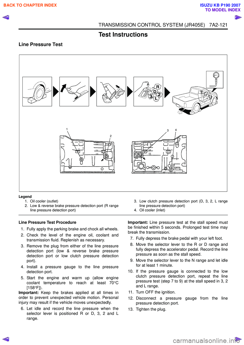
Line Pressure Test
Legend1. Oil cooler (outlet)
2. Low & reverse brake pressure detection port (R range line pressure detection port) 3. Low clutch pressure detection port (D, 3, 2, L range
line pressure detection port)
4. Oil cooler (inlet)
Line Pressure Test Procedure
1. Fully apply the parking brake and chock all wheels.
2. Check the level of the engine oil, coolant and transmission fluid. Replenish as necessary.
3. Remove the plug from either of the line pressure detection port (low & reverse brake pressure
detection port or low clutch pressure detection
port).
4. Install a pressure gauge to the line pressure detection port.
5. Start the engine and warm up (allow engine coolant temperature to reach at least 70 °C
[158 °F]).
Important: Keep the brakes applied at all times in
order to prevent unexpected vehicle motion. Personal
injury may result if the vehicle moves unexpectedly.
6. Let idle and record the line pressure when the selector lever is positioned R or D, 3, 2 and L
range. Important:
Line pressure test at the stall speed must
be finished within 5 seconds. Prolonged test time may
break the transmission.
7. Fully depress the brake pedal with your left foot.
8. Move the selector lever to the R or D range and fully depress the accelerator pedal. Record the line
pressure as soon as the stall speed.
9. Move the selector lever to the N range and let idle for at least 1 minute.
10. If the pressure gauge is connected to the low clutch pressure detection port, repeat the line
pressure test (step 7 to 9) at the stall speed in 3, 2
and L range.
11. Turn OFF the ignition.
12. Disconnect a pressure gauge from the line pressure detection port.
13. Tighten the plug.
1
2 3
4
BACK TO CHAPTER INDEX
TO MODEL INDEX
ISUZU KB P190 2007
Page 4407 of 6020
TRANSMISSION CONTROL SYSTEM (JR405E) 7A2-123
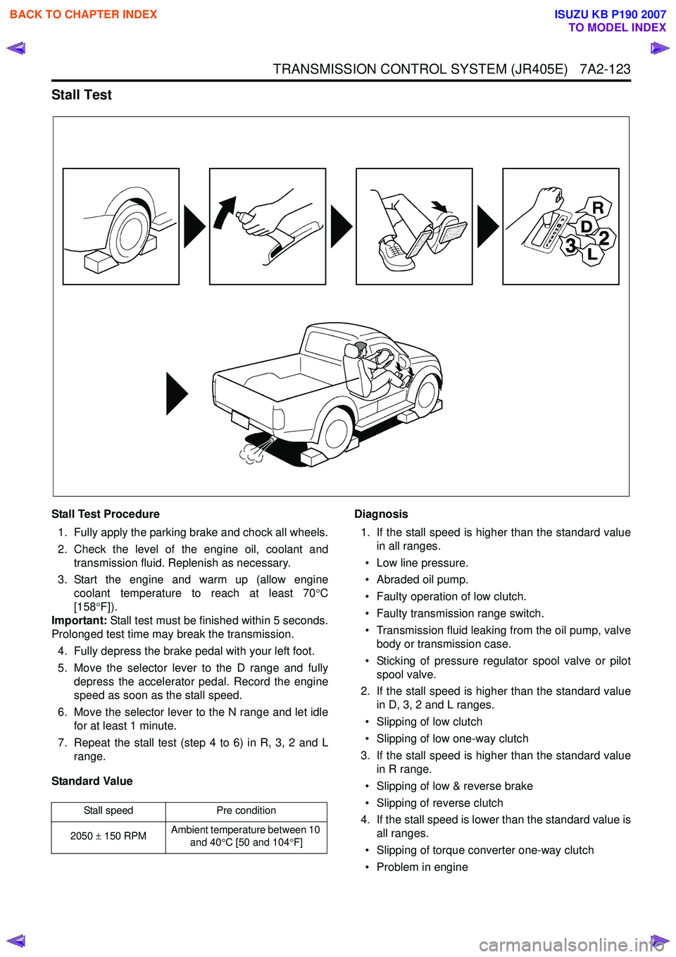
Stall Test
Stall Test Procedure1. Fully apply the parking brake and chock all wheels.
2. Check the level of the engine oil, coolant and transmission fluid. Replenish as necessary.
3. Start the engine and warm up (allow engine coolant temperature to reach at least 70 °C
[158 °F]).
Important: Stall test must be finished within 5 seconds.
Prolonged test time may break the transmission.
4. Fully depress the brake pedal with your left foot.
5. Move the selector lever to the D range and fully depress the accelerator pedal. Record the engine
speed as soon as the stall speed.
6. Move the selector lever to the N range and let idle for at least 1 minute.
7. Repeat the stall test (step 4 to 6) in R, 3, 2 and L range.
Standard Value Diagnosis
1. If the stall speed is higher than the standard value in all ranges.
• Low line pressure.
• Abraded oil pump.
• Faulty operation of low clutch.
• Faulty transmission range switch.
• Transmission fluid leaking from the oil pump, valve body or transmission case.
• Sticking of pressure regulator spool valve or pilot spool valve.
2. If the stall speed is higher than the standard value in D, 3, 2 and L ranges.
• Slipping of low clutch
• Slipping of low one-way clutch
3. If the stall speed is higher than the standard value in R range.
• Slipping of low & reverse brake
• Slipping of reverse clutch
4. If the stall speed is lower than the standard value is all ranges.
• Slipping of torque converter one-way clutch
• Problem in engine
Stall speed Pre condition
2050 ± 150 RPM Ambient temperature between 10
and 40 °C [50 and 104 °F]
BACK TO CHAPTER INDEX
TO MODEL INDEX
ISUZU KB P190 2007
Page 4408 of 6020
7A2-124 TRANSMISSION CONTROL SYSTEM (JR405E)
Time Lag Test
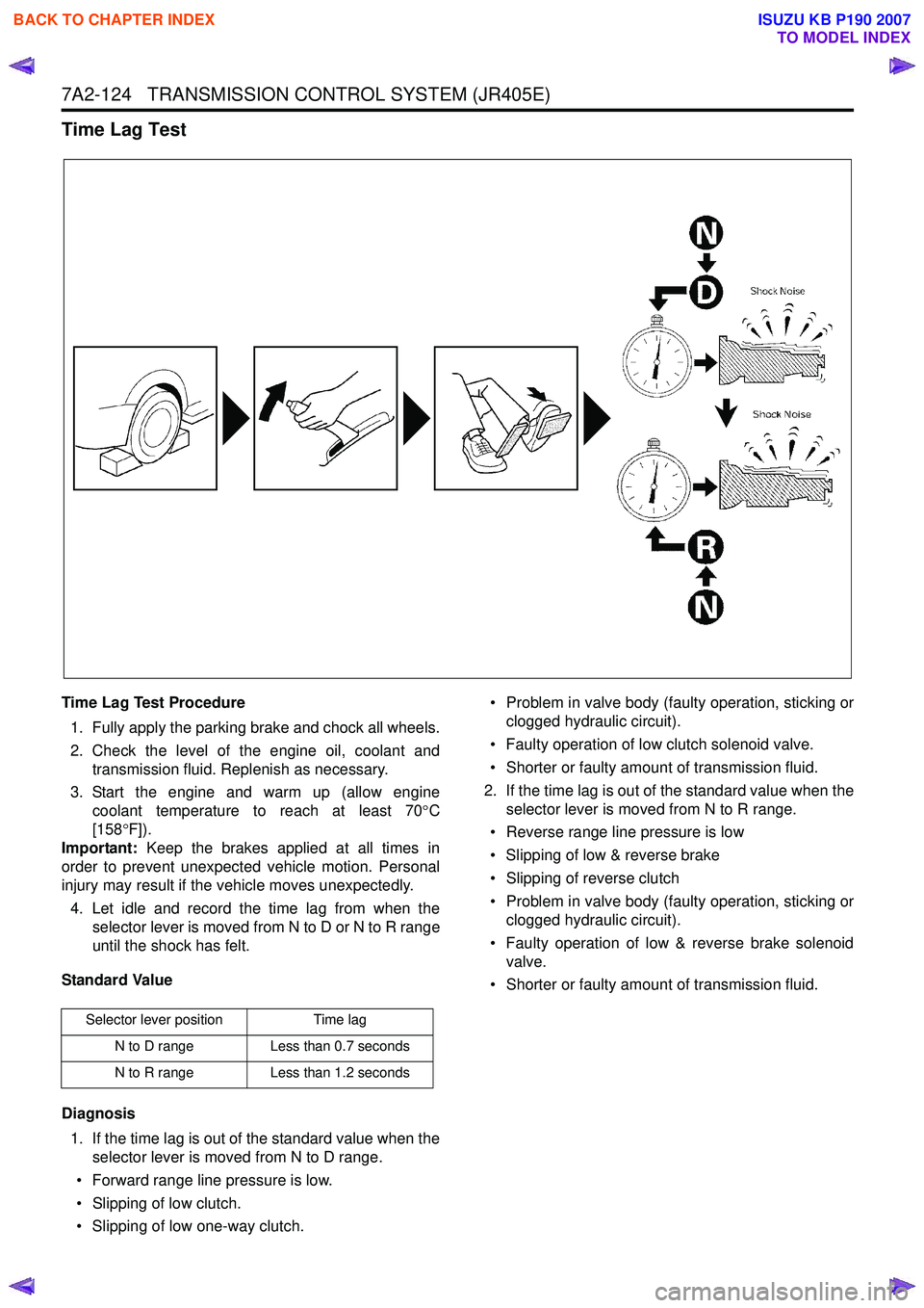
Time Lag Test Procedure1. Fully apply the parking brake and chock all wheels.
2. Check the level of the engine oil, coolant and transmission fluid. Replenish as necessary.
3. Start the engine and warm up (allow engine coolant temperature to reach at least 70 °C
[158 °F]).
Important: Keep the brakes applied at all times in
order to prevent unexpected vehicle motion. Personal
injury may result if the vehicle moves unexpectedly.
4. Let idle and record the time lag from when the selector lever is moved from N to D or N to R range
until the shock has felt.
Standard Value
Diagnosis 1. If the time lag is out of the standard value when the selector lever is moved from N to D range.
• Forward range line pressure is low.
• Slipping of low clutch.
• Slipping of low one-way clutch. • Problem in valve body (faulty operation, sticking or
clogged hydraulic circuit).
• Faulty operation of low clutch solenoid valve.
• Shorter or faulty amount of transmission fluid.
2. If the time lag is out of the standard value when the selector lever is moved from N to R range.
• Reverse range line pressure is low
• Slipping of low & reverse brake
• Slipping of reverse clutch
• Problem in valve body (faulty operation, sticking or clogged hydraulic circuit).
• Faulty operation of low & reverse brake solenoid valve.
• Shorter or faulty amount of transmission fluid.
Selector lever position Time lag
N to D range Less than 0.7 seconds
N to R range Less than 1.2 seconds
BACK TO CHAPTER INDEX
TO MODEL INDEX
ISUZU KB P190 2007
Page 4424 of 6020
7A2-140 TRANSMISSION CONTROL SYSTEM (JR405E)
• Electrically Erasable Programmable Read OnlyMemory (EEPROM)
This type of memory allows selected portions of
memory to be programmed while other portions
remain unchanged.
Certain learned values reside in the EEPROM,
such as:
- The vehicle identification number (VIN)
- The software/ calibrations identification numbers
- The control module security information
• Flash Read Only Memory-Flash Memory
Flash memory has increased memory storage capacity.
During programming, all information within this type of
memory is erased, and then replaced with entirely new
information.
Service Programming Methods
The two methods of programming a TCM are listed
below:
• Remote Programming
• Pass Thru Programming
For information on programming a TCM using one of
the methods listed above, refer to Service
Programming System (SPS) (Remote Procedure) or
Service Programming System (SPS) (Pass-Thru
Procedure).
Before Programming a Control Module
Important: DO NOT program an existing TCM with the
identical software/ calibration package. This procedure
is not a short cut to correct the driveability condition.
This is an ineffective repair. An TCM should only be
programmed when the following occurs:
• When a service procedure instructs you to replace the TCM.
• An updated software/ calibrations is released.
Ensure that the following conditions are met before
programming a TCM:
• The scan tool PCMCIA card is programmed with the latest software.
• The TIS 2000 is installed with the latest software.
• The hardware key is plugged into the computer port.
• Vehicle system voltage:
- There are no charging system concerns. Allcharging system concerns must be repaired
before programming the TCM.
- The battery voltage is greater than 12 volts but less than 16 volts. The battery must be fully
charged before programming the TCM.
- A battery charger is NOT connected to the vehicles battery. Incorrect system voltage or
voltage fluctuations from a battery charger may
cause programming failure or TCM damage. - Turn OFF or disable any system that may put a
load on the vehicles battery. Turn OFF or
disable systems such as:
◊ Heating, ventilation, and air conditioning
(HVAC) systems
◊ Headlights
◊ Room lights
◊ Accessory equipment
• The ignition switch is in the proper position. The scan tool prompts you to turn ON the ignition, with
the engine OFF. DO NOT change the position of
the ignition switch during the programming
procedure unless instructed to do so.
• All tool connections are secure:
- The RS-232 cable
- The connection at the DLC
- The voltage supply circuits
• DO NOT disturb the tool harnesses while programming. If an interruption occurs during the
programming procedure, programming failure or
TCM damage may occur.
• If you are performing the Pass-Thru programming procedure using a notebook computer without the
power cord, ensure that the internal battery is fully
charged.
Service Programming System (SPS)
(Remote Procedure)
Notice: Some module will not accept SPS remote
procedure using 10MB PCMCIA card. In such case,
use 32MB PCMCIA card or SPS pass-thru procedure.
The Remote SPS method is a three-step process that
involves the following procedures:
1. Connecting the scan tool to the vehicle and obtaining the information from the TCM.
2. Connecting the scan tool to the terminal and downloading a new calibration file from the
terminal into the scan tool memory.
3. Reconnecting the scan tool to the vehicle and uploading the new calibration file into the TCM.
Performing the Remote Procedure 1. Connect a scan tool to the vehicle and obtain the TCM information using the following procedure:
Notice: Ensure the TCM is installed in the vehicle and
the battery is fully charged before programming.
a. Install a scan tool.
b. Turn ON the ignition, with the engine OFF.
c. Select Service Programming System (SPS) > Request Info.
BACK TO CHAPTER INDEX
TO MODEL INDEX
ISUZU KB P190 2007
Page 4425 of 6020
TRANSMISSION CONTROL SYSTEM (JR405E) 7A2-141
d. If there is already stored in the scan tool, theexisting data is displayed on the screen. The
scan tool asks user to keep existing data “Keep
Data” or “Continue” to request new vehicle
information from the TCM. If there is no data in
the scan tool, it will immediately start vehicle
identification.
e. Select the vehicle description by following the on-screen instructions based on stamped VIN
or affixed VIN plate on the vehicle.
f. During obtaining information, the scan tool is receiving information from all modules at the
same time. But only ECM information is
displayed on the screen.
g. Turn OFF all accessories and press “Okay”.
h. Verify that the correct VIN is displayed on the scan tool. If the VIN is incorrect or no VIN,
record the correct VIN.
2. Turn OFF the ignition.
3. Turn OFF the scan tool and disconnect from the vehicle.
4. Transfer the data from the terminal to the scan tool using the following procedure:
Notice: The TIS supports service programming with
the Tech 2 scan tool only.
a. Connect the scan tool to the terminal.
b. Launch the TIS application.
c. Select the Service Programming System at the main screen.
d. Highlight the following information on the Select Diagnostic Tool and Programming Process
screen, then click “Next”.
• Select Diagnostic Tool - Tech 2
• Select Programming Process - Identify whether an existing TCM is being
reprogrammed or a TCM is being replaced
with a new one
• Select ECU Location - Vehicle
e. Verify the connections on the Preparing for Communication screen, then click “Next”.
f. Verify the VIN on the Validate Vehicle Identification Number (VIN) screen, then click
“Next”.
Notice: If the TCM is replaced to new one, VIN does
not displayed. Input correct VIN reading from stamped
VIN or affixed VIN plate on the vehicle. If the TCM from
another vehicle is installed, input correct VIN by same
way.
g. Highlight Transmission on the Select SystemType screen, then click “Next”, if on-screen
instruction displayed.
h. Complete the following information based on the service ID plate on the Validate Vehicle
Data screen until “Next” is highlighted, then
click “Next”.
• Model • Model year
• Engine type
• Model designator
• Destination code
• Transmission type
i. Verify your selection on the Summary screen.
Notice: Refer to Service Bulletin and Description
column before service programming is performed if the
bulletins are listed along with the calibration files.
Notice: Select Cancel if you receive a message stating
that the calibration selected is already the current
calibration in the TCM and reprogramming with the
same download is not allowed.
j. Click “Reprog”.
k. The Transfer Data screen will appear until the progress bar reaches 100%.
5. Close the application and return to the TIS application selection screen after the download is
completed.
6. Turn OFF the scan tool and disconnect from the terminal.
7. Transfer the data from the scan tool to the TCM using the following procedure:
a. Install a scan tool.
b. Turn ON the ignition, with the engine OFF.
c. Select Service Programming System (SPS) > Program ECU.
d. Turn OFF all accessories and press “Continue”.
e. Programming in Process will appear until the progress bar reaches 100%.
Notice: Some warning lamp may turn ON or blink while
programming the TCM since communication between
the TCM and other modules are interrupted. Clear DTC
in any module after programming.
f. Press “Continue” and exit the program after thescan tool displays “Programming Was
Successful”.
8. Turn OFF the ignition.
9. Turn OFF the scan tool and disconnect from the vehicle.
Service Programming System (SPS) (Pass-
Thru Procedure)
Pass-Thru programming allows the scan tool to remain
connected to the terminal and to the vehicle throughout
the programming process. The vehicle must be in close
proximity to the terminal while using Pass-Thru.
1. Launch the TIS application.
2. Select the Service Programming System at the main screen.
3. Highlight the following information on the Select Diagnostic Tool and Programming Process screen,
then click “Next”:
• Select Diagnostic Tool-Select Pass - Thru
BACK TO CHAPTER INDEX
TO MODEL INDEX
ISUZU KB P190 2007
Page 4436 of 6020
7A2-152 TRANSMISSION CONTROL SYSTEM (JR405E)
Output Shaft Speed (OSS) Sensor
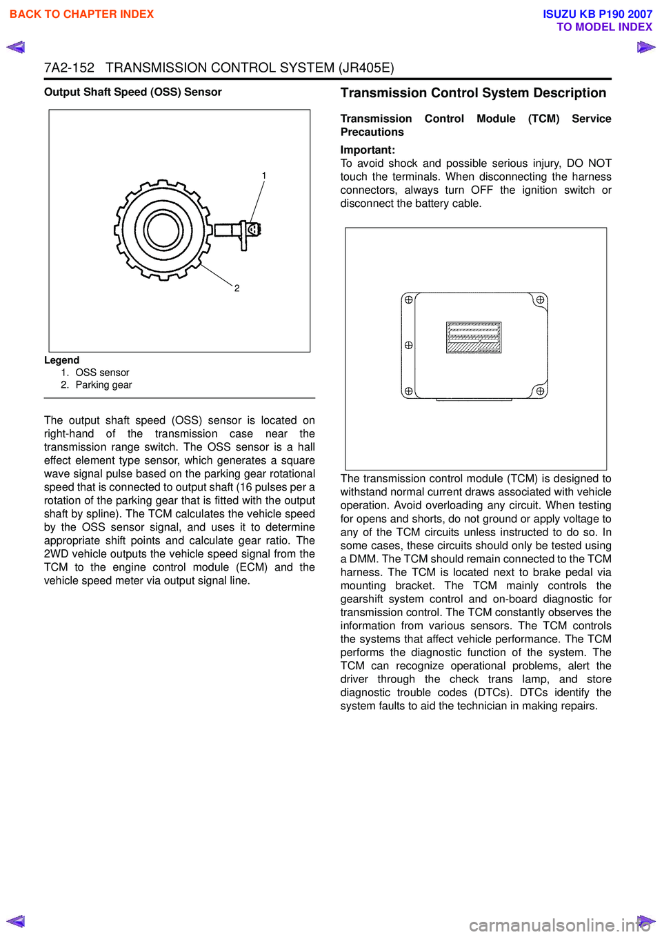
Legend1. OSS sensor
2. Parking gear
The output shaft speed (OSS) sensor is located on
right-hand of the transmission case near the
transmission range switch. The OSS sensor is a hall
effect element type sensor, which generates a square
wave signal pulse based on the parking gear rotational
speed that is connected to output shaft (16 pulses per a
rotation of the parking gear that is fitted with the output
shaft by spline). The TCM calculates the vehicle speed
by the OSS sensor signal, and uses it to determine
appropriate shift points and calculate gear ratio. The
2WD vehicle outputs the vehicle speed signal from the
TCM to the engine control module (ECM) and the
vehicle speed meter via output signal line.
Transmission Control System Description
Transmission Control Module (TCM) Service
Precautions
Important:
To avoid shock and possible serious injury, DO NOT
touch the terminals. When disconnecting the harness
connectors, always turn OFF the ignition switch or
disconnect the battery cable.
The transmission control module (TCM) is designed to
withstand normal current draws associated with vehicle
operation. Avoid overloading any circuit. When testing
for opens and shorts, do not ground or apply voltage to
any of the TCM circuits unless instructed to do so. In
some cases, these circuits should only be tested using
a DMM. The TCM should remain connected to the TCM
harness. The TCM is located next to brake pedal via
mounting bracket. The TCM mainly controls the
gearshift system control and on-board diagnostic for
transmission control. The TCM constantly observes the
information from various sensors. The TCM controls
the systems that affect vehicle performance. The TCM
performs the diagnostic function of the system. The
TCM can recognize operational problems, alert the
driver through the check trans lamp, and store
diagnostic trouble codes (DTCs). DTCs identify the
system faults to aid the technician in making repairs.
1
2
BACK TO CHAPTER INDEX
TO MODEL INDEX
ISUZU KB P190 2007