2007 ISUZU KB P190 relay
[x] Cancel search: relayPage 1924 of 6020
ENGINE CONTROL SYSTEM (4JK1/4JJ1) 6E-307
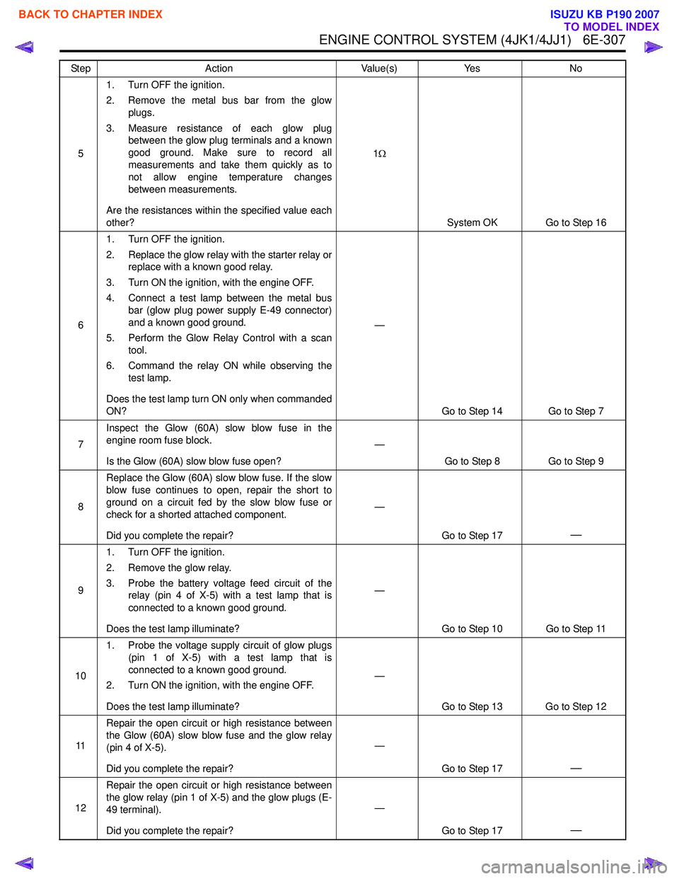
51. Turn OFF the ignition.
2. Remove the metal bus bar from the glow plugs.
3. Measure resistance of each glow plug between the glow plug terminals and a known
good ground. Make sure to record all
measurements and take them quickly as to
not allow engine temperature changes
between measurements.
Are the resistances within the specified value each
other? 1
Ω
System OK Go to Step 16
6 1. Turn OFF the ignition.
2. Replace the glow relay with the starter relay or replace with a known good relay.
3. Turn ON the ignition, with the engine OFF.
4. Connect a test lamp between the metal bus bar (glow plug power supply E-49 connector)
and a known good ground.
5. Perform the Glow Relay Control with a scan tool.
6. Command the relay ON while observing the test lamp.
Does the test lamp turn ON only when commanded
ON? —
Go to Step 14 Go to Step 7
7 Inspect the Glow (60A) slow blow fuse in the
engine room fuse block.
Is the Glow (60A) slow blow fuse open? —
Go to Step 8 Go to Step 9
8 Replace the Glow (60A) slow blow fuse. If the slow
blow fuse continues to open, repair the short to
ground on a circuit fed by the slow blow fuse or
check for a shorted attached component.
Did you complete the repair? —
Go to Step 17
—
91. Turn OFF the ignition.
2. Remove the glow relay.
3. Probe the battery voltage feed circuit of the relay (pin 4 of X-5) with a test lamp that is
connected to a known good ground.
Does the test lamp illuminate? —
Go to Step 10 Go to Step 11
10 1. Probe the voltage supply circuit of glow plugs
(pin 1 of X-5) with a test lamp that is
connected to a known good ground.
2. Turn ON the ignition, with the engine OFF.
Does the test lamp illuminate? —
Go to Step 13 Go to Step 12
11 Repair the open circuit or high resistance between
the Glow (60A) slow blow fuse and the glow relay
(pin 4 of X-5).
Did you complete the repair? —
Go to Step 17
—
12Repair the open circuit or high resistance between
the glow relay (pin 1 of X-5) and the glow plugs (E-
49 terminal).
Did you complete the repair? —
Go to Step 17
—
Step Action Value(s)Yes No
BACK TO CHAPTER INDEX
TO MODEL INDEX
ISUZU KB P190 2007
Page 1925 of 6020
6E-308 ENGINE CONTROL SYSTEM (4JK1/4JJ1)
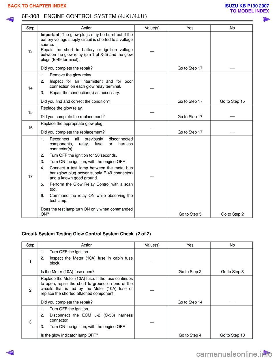
Circuit/ System Testing Glow Control System Check (2 of 2)
13Important
: The glow plugs may be burnt out if the
battery voltage supply circuit is shorted to a voltage
source.
Repair the short to battery or ignition voltage
between the glow relay (pin 1 of X-5) and the glow
plugs (E-49 terminal).
Did you complete the repair? —
Go to Step 17
—
141. Remove the glow relay.
2. Inspect for an intermittent and for poor connection on each glow relay terminal.
3. Repair the connection(s) as necessary.
Did you find and correct the condition? —
Go to Step 17 Go to Step 15
15 Replace the glow relay.
Did you complete the replacement? —
Go to Step 17
—
16Replace the appropriate glow plug.
Did you complete the replacement? —
Go to Step 17—
171. Reconnect all previously disconnected
components, relay, fuse or harness
connector(s).
2. Turn OFF the ignition for 30 seconds.
3. Turn ON the ignition, with the engine OFF.
4. Connect a test lamp between the metal bus bar (glow plug power supply E-49 connector)
and a known good ground.
5. Perform the Glow Relay Control with a scan tool.
6. Command the relay ON while observing the test lamp.
Does the test lamp turn ON only when commanded
ON? —
Go to Step 5 Go to Step 2
Step
Action Value(s)Yes No
Step Action Value(s)Yes No
1 1. Turn OFF the ignition.
2. Inspect the Meter (10A) fuse in cabin fuse block.
Is the Meter (10A) fuse open? —
Go to Step 2 Go to Step 3
2 Replace the Meter (10A) fuse. If the fuse continues
to open, repair the short to ground on one of the
circuits that is fed by the Meter (10A) fuse or
replace the shorted attached component.
Did you complete the repair? —
Go to Step 14
—
31. Turn OFF the ignition.
2. Disconnect the ECM J-2 (C-58) harness connector.
3. Turn ON the ignition, with the engine OFF.
Is the glow indicator lamp OFF? —
Go to Step 4 Go to Step 10
BACK TO CHAPTER INDEX
TO MODEL INDEX
ISUZU KB P190 2007
Page 1928 of 6020
ENGINE CONTROL SYSTEM (4JK1/4JJ1) 6E-311
In-Tank Fuel Pump System Check
Description
The ECM controls the fuel pump relay, which supplies
power to the fuel pump in the fuel tank. The ECM
commands the fuel pump relay ON for a certain length
of time at ignition switch is ON with the engine OFF.
During the engine is running it is continuity commanded
ON.
In-tank Fuel Pump Control Operation • The battery voltage is more than 9 volts. • The ignition switch is ON.
• The fuel pump is commanded ON for 12 seconds at ignition switch is ON with the engine OFF.
• The fuel pump is continuously ON while engine is running.
Schematic Reference: Engine Controls Schematics
Connector End View Reference: Engine Controls
Connector End Views or ECM Connector End Views
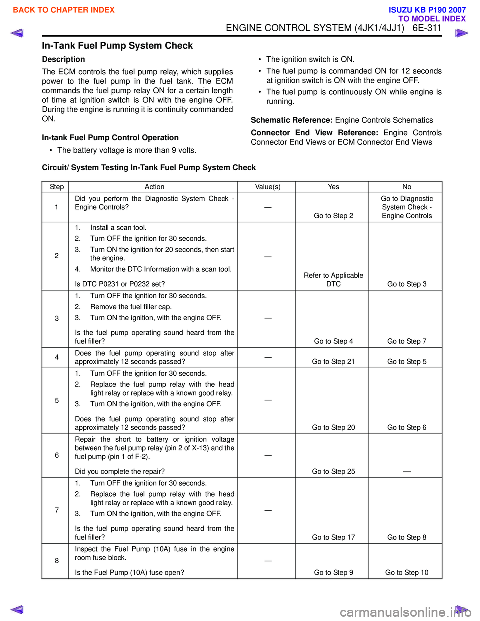
Circuit/ System Testing In-Tank Fuel Pump System Check
Step Action Value(s)Yes No
1 Did you perform the Diagnostic System Check -
Engine Controls? —
Go to Step 2 Go to Diagnostic
System Check -
Engine Controls
2 1. Install a scan tool.
2. Turn OFF the ignition for 30 seconds.
3. Turn ON the ignition for 20 seconds, then start the engine.
4. Monitor the DTC Information with a scan tool.
Is DTC P0231 or P0232 set? —
Refer to Applicable DTC Go to Step 3
3 1. Turn OFF the ignition for 30 seconds.
2. Remove the fuel filler cap.
3. Turn ON the ignition, with the engine OFF.
Is the fuel pump operating sound heard from the
fuel filler? —
Go to Step 4 Go to Step 7
4 Does the fuel pump operating sound stop after
approximately 12 seconds passed? —
Go to Step 21 Go to Step 5
5 1. Turn OFF the ignition for 30 seconds.
2. Replace the fuel pump relay with the head light relay or replace with a known good relay.
3. Turn ON the ignition, with the engine OFF.
Does the fuel pump operating sound stop after
approximately 12 seconds passed? —
Go to Step 20 Go to Step 6
6 Repair the short to battery or ignition voltage
between the fuel pump relay (pin 2 of X-13) and the
fuel pump (pin 1 of F-2).
Did you complete the repair? —
Go to Step 25
—
71. Turn OFF the ignition for 30 seconds.
2. Replace the fuel pump relay with the head light relay or replace with a known good relay.
3. Turn ON the ignition, with the engine OFF.
Is the fuel pump operating sound heard from the
fuel filler? —
Go to Step 17 Go to Step 8
8 Inspect the Fuel Pump (10A) fuse in the engine
room fuse block.
Is the Fuel Pump (10A) fuse open? —
Go to Step 9 Go to Step 10
BACK TO CHAPTER INDEX
TO MODEL INDEX
ISUZU KB P190 2007
Page 1929 of 6020
6E-312 ENGINE CONTROL SYSTEM (4JK1/4JJ1)
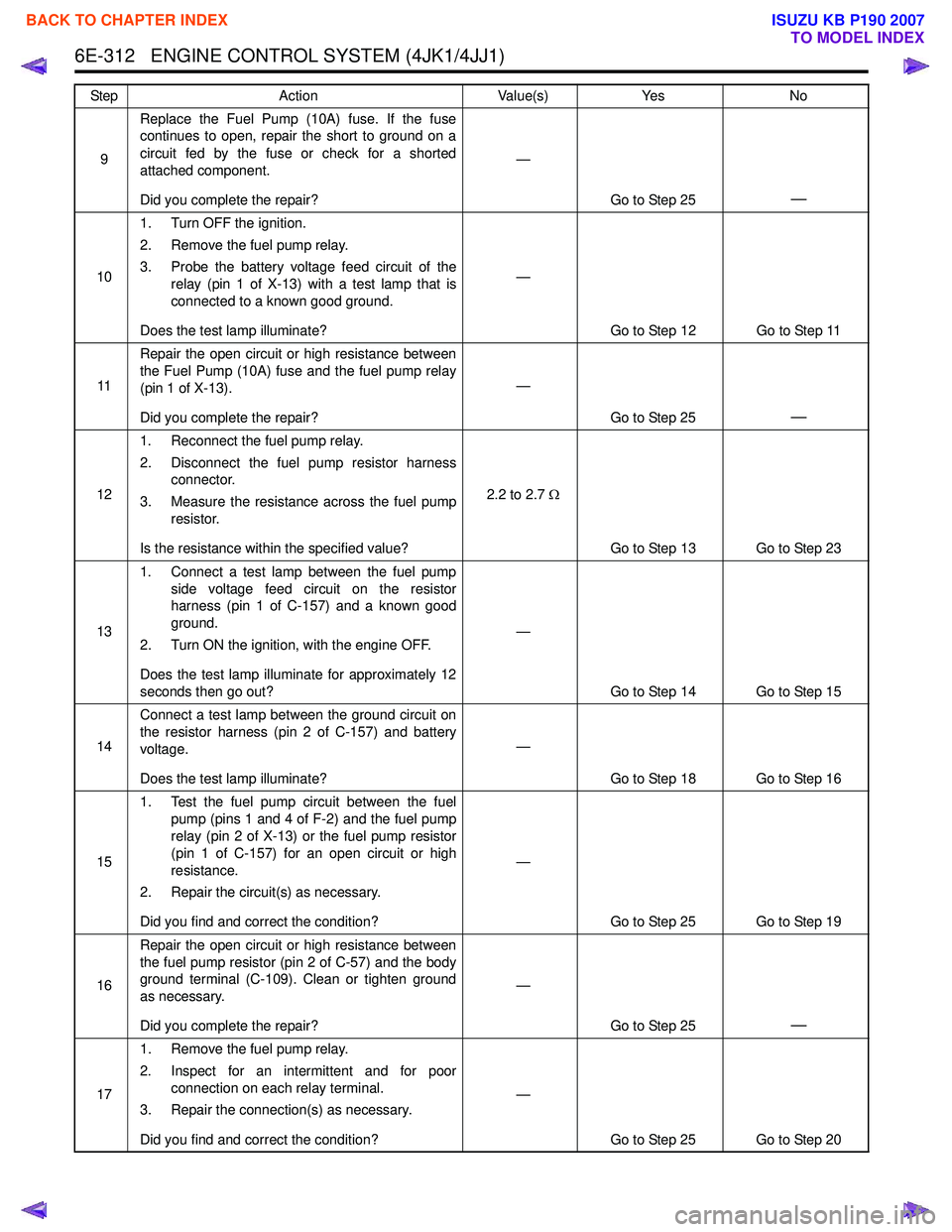
9Replace the Fuel Pump (10A) fuse. If the fuse
continues to open, repair the short to ground on a
circuit fed by the fuse or check for a shorted
attached component.
Did you complete the repair? —
Go to Step 25
—
101. Turn OFF the ignition.
2. Remove the fuel pump relay.
3. Probe the battery voltage feed circuit of the relay (pin 1 of X-13) with a test lamp that is
connected to a known good ground.
Does the test lamp illuminate? —
Go to Step 12 Go to Step 11
11 Repair the open circuit or high resistance between
the Fuel Pump (10A) fuse and the fuel pump relay
(pin 1 of X-13).
Did you complete the repair? —
Go to Step 25
—
121. Reconnect the fuel pump relay.
2. Disconnect the fuel pump resistor harness connector.
3. Measure the resistance across the fuel pump resistor.
Is the resistance within the specified value? 2.2 to 2.7
Ω
Go to Step 13 Go to Step 23
13 1. Connect a test lamp between the fuel pump
side voltage feed circuit on the resistor
harness (pin 1 of C-157) and a known good
ground.
2. Turn ON the ignition, with the engine OFF.
Does the test lamp illuminate for approximately 12
seconds then go out? —
Go to Step 14 Go to Step 15
14 Connect a test lamp between the ground circuit on
the resistor harness (pin 2 of C-157) and battery
voltage.
Does the test lamp illuminate? —
Go to Step 18 Go to Step 16
15 1. Test the fuel pump circuit between the fuel
pump (pins 1 and 4 of F-2) and the fuel pump
relay (pin 2 of X-13) or the fuel pump resistor
(pin 1 of C-157) for an open circuit or high
resistance.
2. Repair the circuit(s) as necessary.
Did you find and correct the condition? —
Go to Step 25 Go to Step 19
16 Repair the open circuit or high resistance between
the fuel pump resistor (pin 2 of C-57) and the body
ground terminal (C-109). Clean or tighten ground
as necessary.
Did you complete the repair? —
Go to Step 25
—
171. Remove the fuel pump relay.
2. Inspect for an intermittent and for poor connection on each relay terminal.
3. Repair the connection(s) as necessary.
Did you find and correct the condition? —
Go to Step 25 Go to Step 20
Step
Action Value(s)Yes No
BACK TO CHAPTER INDEX
TO MODEL INDEX
ISUZU KB P190 2007
Page 1930 of 6020
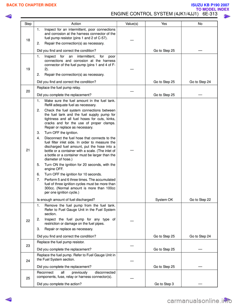
ENGINE CONTROL SYSTEM (4JK1/4JJ1) 6E-313
181. Inspect for an intermittent, poor connections
and corrosion at the harness connector of the
fuel pump resistor (pins 1 and 2 of C-57).
2. Repair the connection(s) as necessary.
Did you find and correct the condition? —
Go to Step 25
—
191. Inspect for an intermittent, for poor
connections and corrosion at the harness
connector of the fuel pump (pins 1 and 4 of F-
2).
2. Repair the connection(s) as necessary.
Did you find and correct the condition? —
Go to Step 25 Go to Step 24
20 Replace the fuel pump relay.
Did you complete the replacement? —
Go to Step 25
—
211. Make sure the fuel amount in the fuel tank.
Refill adequate fuel as necessary.
2. Check the fuel system connections between the fuel tank and the fuel supply pump for
tightness and all fuel hoses for cuts, kinks,
cracks and for the use of proper clamps.
Repair or replace as necessary.
3. Turn OFF the ignition.
4. Disconnect the fuel hose that connects to the fuel filter inlet side. In order to measure the
discharged fuel amount, put the hose into a
bottle or a container with a scale. (The inlet of
a bottle or a container must be larger than the
diameter of hose.)
5. Turn ON the ignition for 20 seconds, with the engine OFF.
6. Turn OFF the ignition for 10 seconds.
7. Perform 5 and 6 three times. The accumulated fuel of three ignition cycles must be more than
300cc. (Normal amount is more than 100cc
per one ignition cycle.)
Is enough amount of fuel discharged? —
System OK Go to Step 22
22 1. Remove the fuel pump from the fuel tank.
Refer to Fuel Gauge Unit in the Fuel System
section.
2. Inspect the fuel pump for any type of restriction or damage on the fuel pipes.
3. Repair or replace as necessary.
Did you find and correct the condition? —
Go to Step 25 Go to Step 24
23 Replace the fuel pump resistor.
Did you complete the replacement? —
Go to Step 25
—
24Replace the fuel pump. Refer to Fuel Gauge Unit in
the Fuel System section.
Did you complete the replacement? —
Go to Step 25
—
25Reconnect all previously disconnected
components, fuse, relay or harness connector(s).
Did you complete the action? —
Go to Step 3
—
Step Action Value(s)Yes No
BACK TO CHAPTER INDEX
TO MODEL INDEX
ISUZU KB P190 2007
Page 1941 of 6020

6E-324 ENGINE CONTROL SYSTEM (4JK1/4JJ1)
• The MIL/ SVS lamp circuit intermittently shorted toground
• Electrical system interference caused by a malfunctioning relay, ECM driven solenoid, or
switch. The electrical component can cause a
sharp electrical surge. Normally, the problem will
occur when the malfunctioning component is
operating.
• There are any open diodes.
Important: The following symptom tables contain
groups of possible causes for each symptom. The
order of these procedures is not important. If the scan
tool readings do not indicate the problems, then
proceed in a logical order, easiest to check or most
likely to cause first. In order to determine if a specific
vehicle is using a particular system or component, refer
to Engine Controls Schematics for an application.
Use the following tables when diagnosing a symptom
complaint:
• Intermittent Conditions
• Hard Start
• Rough, Unstable, or Incorrect Idle and Stalling
• High Idle Speed
•Cuts Out
• Surges
• Lack of Power, Sluggishness or Sponginess
• Hesitation, Sag or Stumble
• Abnormal Combustion Noise
• Poor Fuel Economy
• Excessive Smoke (Black Smoke)
• Excessive Smoke (White Smoke)
BACK TO CHAPTER INDEX
TO MODEL INDEX
ISUZU KB P190 2007
Page 1943 of 6020
6E-326 ENGINE CONTROL SYSTEM (4JK1/4JJ1)
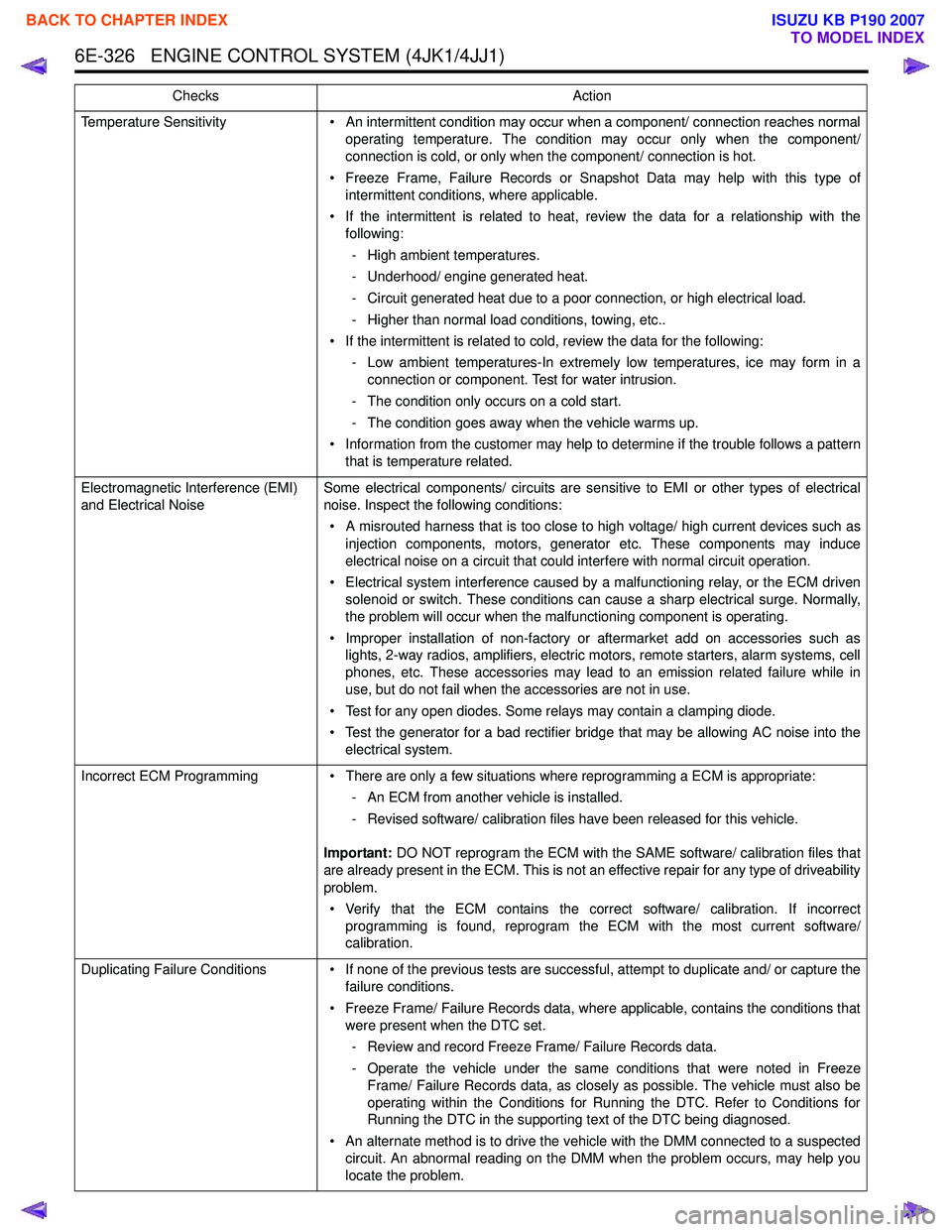
Temperature Sensitivity• An intermittent condition may occur when a component/ connection reaches normal
operating temperature. The condition may occur only when the component/
connection is cold, or only when the component/ connection is hot.
• Freeze Frame, Failure Records or Snapshot Data may help with this type of intermittent conditions, where applicable.
• If the intermittent is related to heat, review the data for a relationship with the following:
- High ambient temperatures.
- Underhood/ engine generated heat.
- Circuit generated heat due to a poor connection, or high electrical load.
- Higher than normal load conditions, towing, etc..
• If the intermittent is related to cold, review the data for the following: - Low ambient temperatures-In extremely low temperatures, ice may form in aconnection or component. Test for water intrusion.
- The condition only occurs on a cold start.
- The condition goes away when the vehicle warms up.
• Information from the customer may help to determine if the trouble follows a pattern that is temperature related.
Electromagnetic Interference (EMI)
and Electrical Noise Some electrical components/ circuits are sensitive to EMI or other types of electrical
noise. Inspect the following conditions:
• A misrouted harness that is too close to high voltage/ high current devices such as injection components, motors, generator etc. These components may induce
electrical noise on a circuit that could interfere with normal circuit operation.
• Electrical system interference caused by a malfunctioning relay, or the ECM driven solenoid or switch. These conditions can cause a sharp electrical surge. Normally,
the problem will occur when the malfunctioning component is operating.
• Improper installation of non-factory or aftermarket add on accessories such as lights, 2-way radios, amplifiers, electric motors, remote starters, alarm systems, cell
phones, etc. These accessories may lead to an emission related failure while in
use, but do not fail when the accessories are not in use.
• Test for any open diodes. Some relays may contain a clamping diode.
• Test the generator for a bad rectifier bridge that may be allowing AC noise into the electrical system.
Incorrect ECM Programming • There are only a few situations where reprogramming a ECM is appropriate:
- An ECM from another vehicle is installed.
- Revised software/ calibration files have been released for this vehicle.
Important: DO NOT reprogram the ECM with the SAME software/ calibration files that
are already present in the ECM. This is not an effective repair for any type of driveability
problem.
• Verify that the ECM contains the correct software/ calibration. If incorrect programming is found, reprogram the ECM with the most current software/
calibration.
Duplicating Failure Conditions • If none of the previous tests are successful, attempt to duplicate and/ or capture the failure conditions.
• Freeze Frame/ Failure Records data, where applicable, contains the conditions that were present when the DTC set.
- Review and record Freeze Frame/ Failure Records data.
- Operate the vehicle under the same conditions that were noted in Freeze Frame/ Failure Records data, as closely as possible. The vehicle must also be
operating within the Conditions for Running the DTC. Refer to Conditions for
Running the DTC in the supporting text of the DTC being diagnosed.
• An alternate method is to drive the vehicle with the DMM connected to a suspected circuit. An abnormal reading on the DMM when the problem occurs, may help you
locate the problem.
Checks
Action
BACK TO CHAPTER INDEX
TO MODEL INDEX
ISUZU KB P190 2007
Page 1971 of 6020
6E-354 ENGINE CONTROL SYSTEM (4JK1/4JJ1)
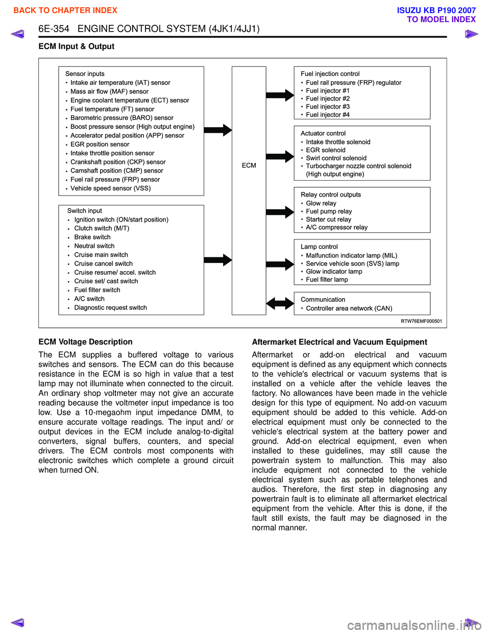
ECM Input & Output
ECM Voltage Description
The ECM supplies a buffered voltage to various
switches and sensors. The ECM can do this because
resistance in the ECM is so high in value that a test
lamp may not illuminate when connected to the circuit.
An ordinary shop voltmeter may not give an accurate
reading because the voltmeter input impedance is too
low. Use a 10-megaohm input impedance DMM, to
ensure accurate voltage readings. The input and/ or
output devices in the ECM include analog-to-digital
converters, signal buffers, counters, and special
drivers. The ECM controls most components with
electronic switches which complete a ground circuit
when turned ON. Aftermarket Electrical and Vacuum Equipment
Aftermarket or add-on electrical and vacuum
equipment is defined as any equipment which connects
to the vehicle's electrical or vacuum systems that is
installed on a vehicle after the vehicle leaves the
factory. No allowances have been made in the vehicle
design for this type of equipment. No add-on vacuum
equipment should be added to this vehicle. Add-on
electrical equipment must only be connected to the
vehicle's electrical system at the battery power and
ground. Add-on electrical equipment, even when
installed to these guidelines, may still cause the
powertrain system to malfunction. This may also
include equipment not connected to the vehicle
electrical system such as portable telephones and
audios. Therefore, the first step in diagnosing any
powertrain fault is to eliminate all aftermarket electrical
equipment from the vehicle. After this is done, if the
fault still exists, the fault may be diagnosed in the
normal manner.
RTW76EMF000501
Sensor inputs
· Intake air temperature (IAT) sensor
· Mass air flow (MAF) sensor
· Engine coolant temperature (ECT) sensor
· Fuel temperature (FT) sensor
· Barometric pressure (BARO) sensor
· Boost pressure sensor (High output engine)
· Accelerator pedal position (APP) sensor
· EGR position sensor
· Intake throttle position sensor
· Crankshaft position (CKP) sensor
· Camshaft position (CMP) sensor
· Fuel rail pressure (FRP) sensor
· Vehicle speed sensor (VSS)
Switch input
· Ignition switch (ON/start position)
· Clutch switch (M/T)
· Brake switch
· Neutral switch
· Cruise main switch
· Cruise cancel switch
· Cruise resume/ accel. switch
· Cruise set/ cast switch
· Fuel filter switch
· A/C switch
· Diagnostic request switch
Fuel injection control
· Fuel rail pressure (FRP) regulator
· Fuel injector #1
· Fuel injector #2
· Fuel injector #3
· Fuel injector #4
Relay control outputs
· Glow relay
· Fuel pump relay
· Starter cut relay
· A/C compressor relay
Lamp control
· Malfunction indicator lamp (MIL)
· Service vehicle soon (SVS) lamp
· Glow indicator lamp
· Fuel filter lamp
Communication
· Controller area network (CAN)
Actuator control
· Intake throttle solenoid
· EGR solenoid
· Swirl control solenoid
· Turbocharger nozzle control solenoid
(High output engine)ECM
BACK TO CHAPTER INDEX
TO MODEL INDEX
ISUZU KB P190 2007