2007 ISUZU KB P190 fuel filter
[x] Cancel search: fuel filterPage 3225 of 6020
Fuel System – V6 Page 6C – 23
4.5 Modular Fuel Pump and Sender
Assembly
NOTE
If the modular fuel pump and sender assembly
develops a fault it must be replaced as a
complete unit. The only serviced parts are the
retainer locking ring and the O-ring seal.
Remove
• A depressurised fuel system contains fuel
in the fuel filter and fuel lines that can be
spilled during service operations.
• Fuel vapour remains in the fuel tank even
when completely empty. Seal all openings
in the fuel tank using suitable material or a
plastic plug. Ensure no naked flames or
other ignition sources are nearby. Ensure
all cellular phones (and transmission
devices that may cause any metal objects
to become unintentional receiving
antennas) are switched off.
• Place a dry chemical (Class B) fire
extinguisher nearby before performing any
on-vehicle service procedures. Failure to
follow these precautions may result in
personal injury.
• Wear safety glasses when using
compressed air. Do not blow compressed
air directly onto any body part.
1 Remove the fuel pump relay, refer to 8A Engine Body and Chassis.
2 Remove the fuel tank assembly from the vehicle, refer to 4.4 Fuel Tank.
Before proceeding, clean all traces of dirt and
other foreign material from the top of the fuel
tank, near the modular fuel pump and sender
assembly.
3 Use compressed air to ensure all dirt and foreign materials are removed from all fuel connections before disconnecting the parts.
Fuel can spill from the disconnected modular
fuel pump and sender assembly.
BACK TO CHAPTER INDEX
TO MODEL INDEX
ISUZU KB P190 2007
Page 3230 of 6020
Fuel System – V6 Page 6C – 28
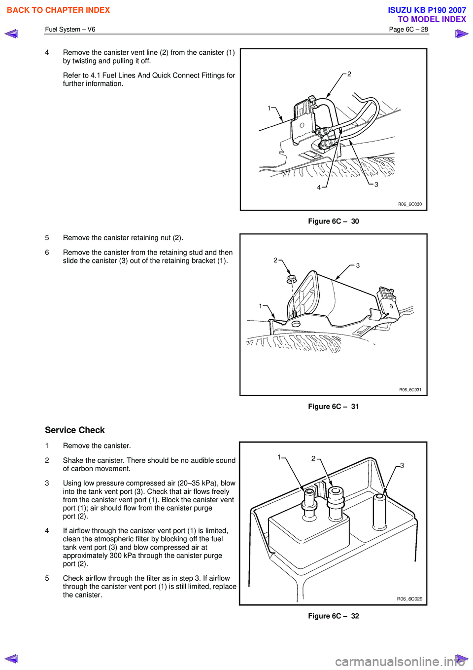
4 Remove the canister vent line (2) from the canister (1)
by twisting and pulling it off.
Refer to 4.1 Fuel Lines And Quick Connect Fittings for further information.
Figure 6C – 30
5 Remove the canister retaining nut (2).
6 Remove the canister from the retaining stud and then slide the canister (3) out of the retaining bracket (1).
Figure 6C – 31
Service Check
1 Remove the canister.
2 Shake the canister. There should be no audible sound of carbon movement.
3 Using low pressure compressed air (20–35 kPa), blow into the tank vent port (3). Check that air flows freely
from the canister vent port (1). Block the canister vent
port (1); air should flow from the canister purge
port (2).
4 If airflow through the canister vent port (1) is limited, clean the atmospheric filter by blocking off the fuel
tank vent port (3) and blow compressed air at
approximately 300 kPa through the canister purge
port (2).
5 Check airflow through the filter as in step 3. If airflow through the canister vent port (1) is still limited, replace
the canister.
Figure 6C – 32
BACK TO CHAPTER INDEX
TO MODEL INDEX
ISUZU KB P190 2007
Page 3235 of 6020
Fuel System – V6 Page 6C – 33
4.9 Fuel Lines
Remove
• A depressurised fuel system contains fuel
in the fuel filter and fuel lines that can be
spilled during service operations.
• Fuel vapour remains in the fuel tank even
when completely empty. Seal all openings
in the fuel tank using suitable material or a
plastic plug. Ensure no naked flames or
other ignition sources are nearby. Ensure
all cellular phones (and transmission
devices that may cause any metal objects
to become unintentional receiving
antennas) are switched off.
• Place a dry chemical (Class B) fire
extinguisher nearby before performing any
on-vehicle service procedures. Failure to
follow these precautions may result in
personal injury.
• Wear safety glasses when using
compressed air. Do not blow compressed
air onto any body part.
1 Remove the fuel pump relay, refer to 8A Electrical Body and Chassis.
2 Depressurise the fuel system, refer to 3.4 Fuel System Depressurisation.
Never drain or store fuel into an open
container, due to the possibility of fire or
explosion.
3 Raise the vehicle, preferably on a hoist, refer to 0A General Information.
Before proceeding, clean all traces of dirt and
other foreign material from the fuel lines.
4 Use compressed air to ensure that all dirt and foreign materials are removed from all fuel connections before the parts are disconnected.
5 If required, remove the stone guard, refer to Figure 6C – 17 and fuel lines. Use the following illustrations showing the fuel line layout and location of other items relating to the fuel system as a guide, also refer to 4.1 Fuel Lines
And Quick Connect Fittings and 4.6 Evaporative Emission Control Canister.
BACK TO CHAPTER INDEX
TO MODEL INDEX
ISUZU KB P190 2007
Page 3237 of 6020
Fuel System – V6 Page 6C – 35
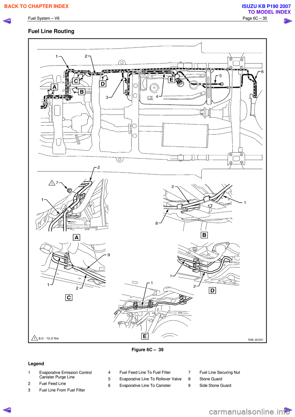
Fuel Line Routing
Figure 6C – 39
Legend
1 Evaporative Emission Control Canister Purge Line
2 Fuel Feed Line
3 Fuel Line From Fuel Filter 4 Fuel Feed Line To Fuel Filter
5 Evaporative Line To Rollover Valve
6 Evaporative Line To Canister
7 Fuel Line Securing Nut
8 Stone Guard
9 Side Stone Guard
BACK TO CHAPTER INDEX
TO MODEL INDEX
ISUZU KB P190 2007
Page 3252 of 6020
Engine Management – V6 – General Information Page 6C1-1–10
Fuel Injection System
Each cylinder of the V6 engine is fitted with one fuel injector. The engine control relay applies ignition positive voltage to
the fuel injector ignition circuit. The ECM controls the operation of the fuel injectors by applying a pulse width modulated
(PW M) ground to the fuel injector control circuit to control each fuel injector on-time.
W hile the engine is running, the ECM constantly monitors the various inputs and recalculates the appropriate on-time for
each injector. The calculation is based on the following:
• The injector flow rate,
• Mass of fuel passed by the energised injector per unit of time,
• The desired air / fuel ratio, and
• Actual air mass in each cylinder.
The ECM calculates the duration of the fuel injector on-time to deliver the correct amount of fuel for optimum drivability
and emission control. The period of time the fuel injector is energised is called the injector on-time and is measured in
milliseconds (thousandths of a second).
The V6 engine uses the sequential fuel injection system. Each fuel injector is energised individually at the correct
moment during its firing stroke as the cylinder’s intake valves are closing to provide enough time for the fuel to atomise
completely and mix with the intake air.
Short Term Fuel Trim
The short term fuel trim (STFT) represents the duration of the fuel injector on-time as calculated by the ECM, while the
ECM is in Closed Loop mode. The STFT allows the ECM to calculate the fuel injector on-time based on the heated
oxygen sensor (HO2S) signal input to the ECM. Therefore, the STFT is disabled when the ECM is in Open Loop mode.
• If the air / fuel mixture in the exhaust is balanced (lambda = 1) or when the STFT is disabled, the STFT value is 0%.
• W hen the HO2S sends an input signal to the ECM indicating the air / fuel mixture is rich, the STFT will be less than
0%, which indicates the ECM is decreasing the fuel injector on-time to reduce the amount of fuel in the air / fuel
mixture.
• W hen the HO2S sends an input signal to the ECM indicating the air / fuel mixture is lean, the STFT will be greater
than 0%, which indicates the ECM is increasing the fuel injector on-time to increase the amount of fuel in the air /
fuel mixture.
The percentage values of the STFT range from –25% to +25% and are directly proportional to the duration of the fuel
injector on-time.
Long Term Fuel Trim
The ECM stores the long term fuel trim (LTFT) in its memory to adjust the fuel injector on-time according to the long term
changes or deterioration in the engine components. The normal LTFT value is 0%.
The following describes the LTFT operation when the engine air filter is dirty that causes a restricted intake airflow fault
condition:
1 The HO2S sends an input signal to the ECM the air / fuel mixture is rich because of the reduced airflow. The STFT may reduce to a value of –10%, which decreases the fuel injector on-time to reduce the amount of fuel in the air /
fuel mixture supplied to the engine.
W ithout the use of the LTFT, the restricted airflow caused by the dirty air filter may reduce the STFT value to –10% until the air filter is replaced. This will decrease the range of negative adjustment available to the STFT to
compensate for other factors.
2 W hen the ECM detects the STFT has remained at –10% for a specific period, the ECM switches to the LTFT. The LTFT adjusts the duration of the fuel injector on-time until the air / fuel mixture in the exhaust is balanced (lambda =
1) and the STFT value returns to 0%.
3 The ECM stores this Long Term FT value in its memory, which is used to calculate the base fuel injector on-time.
The percentage values of the Long Term FT range from –100% to +100%. If the ECM detects the LTFT values are
outside the specified percentage range for a predetermined period, the ECM will set a Diagnostic Trouble Code and
switch to Open Loop mode.
BACK TO CHAPTER INDEX
TO MODEL INDEX
ISUZU KB P190 2007
Page 3258 of 6020
Engine Management – V6 – General Information Page 6C1-1–16
W hen ECM commands the EVAP valve (1) to open, the fuel
vapours are drawn from the canister line (2) into the intake
manifold where it is consumed in the normal combustion
process.
Figure 6C1-1 – 10
The ECM energises the EVAP valve when the appropriate conditions have been met, such as:
• Engine coolant temperature is less than 20 °C at cold start up and the engine has been running longer than
three minutes and 10 seconds, or
• Engine coolant temperature is greater than 80 °C and the engine has been running longer than five seconds, or
• Engine is not in decel fuel cut-off mode and the throttle opening is less than 96%, or
• The engine is in closed loop fuel mode.
A higher purge rate is used under conditions that are likely to produce large amounts of vapour, when the following
conditions have been met:
• Intake air temperature is greater than 50 °C, or
• Engine coolant temperature is greater than 100 °C, or
• The engine has been running for greater than 15 minutes.
The EVAP purge PW M duty cycle varies according to operating conditions determined by mass air flow, fuel trim and
intake air temperature. The EVAP canister purge valve is re-enabled when throttle position angle decreases below 96%.
For further information on the evaporative emission control system, refer to 6C Fuel System.
Engine Ventilation System
The engine ventilation system contains a Positive crankcase
ventilation (PCV) valve (1) located in the right-hand
camshaft cover. A hose is routed from the PCV valve to
each side of the intake manifold which provides an even
distribution of crankcase fumes, thereby improving spark
plug reliability and a reduction in emissions.
A breather pipe is routed from the intake manifold to the left-
hand camshaft cover and provides fresh filtered air from the
intake duct to the engine.
For further information of the engine ventilation system,
refer to 6A1 Engine Mechanical – V6.
Figure 6C1-1 – 11
BACK TO CHAPTER INDEX
TO MODEL INDEX
ISUZU KB P190 2007
Page 3303 of 6020
Engine Management – V6 – Diagnostics Page 6C1-2–25
Checks Actions
Fuel System
• Check the fuel system for the following fault conditions. Refer to 6C Fuel System
– V6 – V6.
• restricted fuel filter,
• incorrect fuel pressure, and
• contaminated fuel.
• Check the operation of the fuel injectors. Refer to 6C1-3 Engine Management –
V6 – Service Operations.
• Perform the fuel injector balance test, refer to 6.3 Fuel Injector Balance
Test in this Section.
• Check the items that can cause an engine to run lean.
• Check the items that cause an engine to run rich.
Ignition System
• Check for an intermittent ignition circuit malfunction.
• Inspect for moisture or corrosion around the spark plug / ignition coil area.
• Test the ignition coil voltage output. Refer to 6C1-3 Engine Management – V6 –
Service Operations.
• Remove and inspect the spark plugs. Refer to 6C1-3 Engine Management – V6 –
Service Operations.
NOTE
If the spark plugs are fouled, determine the cause of the fouling before
replacing the spark plugs. Refer to 6C1-3 Engine Management – V6 –
Service Operations.
• Check for loose ignition coil ground circuit.
Engine Cooling System Check the engine for over-heating. Refer to 6B1 Engine Cooling – V6.
Engine Mechanical Check for the following engine fault conditions. Refer to 6A1 Engine Mechanical – V6.
• low compression, and
• worn valve train components.
Additional Checks
• Check the exhaust system for possible restrictions. Refer to 6F Exhaust System –
V6.
• Electromagnetic interference (EMI) on the crankshaft position (CKP) sensor can
cause an engine misfire condition.
Using Tech 2, monitor the engine speed parameter. A sudden increase in the engine speed parameters without moving the throttle position indicates that an
Electromagnetic Interference fault may be present.
W iring harness routing which may be positioned very close to a high voltage or high current device such as the following may induce EMI:
• secondary ignition components, or
• motors and generators.
Dirty starter motor commutator or brushes can mask the crankshaft position sensor signal.
• Check the torque converter clutch (TCC) operation. A TCC that applies too soon
can cause engine detonation, which will trigger spark retard activity. Refer to 7C1
Automatic Transmission – 4L60E – General Information.
When all diagnosis and repairs are completed, check the system for correct operation.
BACK TO CHAPTER INDEX
TO MODEL INDEX
ISUZU KB P190 2007
Page 3304 of 6020
Engine Management – V6 – Diagnostics Page 6C1-2–26
5.4 Cranks But Does Not Run
Definition
The engine cranks normally but does not start.
Checks Actions
Preliminary • Perform the preliminary checks. Refer to 4.3 Preliminary Checks in this
Section.
• Check the immobiliser system for correct operation. Refer to 11A Immobiliser.
Sensor / System
• Check the engine coolant temperature (ECT) sensor for an incorrect value.
Compare the engine coolant temperature against the intake air temperature (IAT)
on a cold engine. The ECT and IAT sensor values should be within ± 3°C of each
other. Refer to 6C1-3 Engine Management – V6 – Service Operations for details
of the Temperature vs. Resistance Table.
• Check the mass air flow (MAF) sensor installation. Incorrect installation of the
MAF sensor may cause hard start condition. Refer to 6C1-3 Engine Management
– V6 – Service Operations.
• Check for a dirty starter motor commutator or brushes that can mask the
crankshaft position sensor signal.
Fuel System • Check the fuel system for the following fault conditions. Refer to 6C Fuel System
– V6.
• restricted fuel filter,
• incorrect fuel pressure,
• contaminated fuel, and
• incorrect fuel pump relay operation.
• Check the operation of the fuel injectors. Refer to 6C1-3 Engine Management –
V6 – Service Operations.
Ignition System • Inspect for moisture or corrosion around the spark plug / ignition coil area.
• Test the ignition coil voltage output. Refer to 6C1-3 Engine Management – V6 –
Service Operations.
• Remove and inspect the spark plugs. Refer to 6C1-3 Engine Management – V6 –
Service Operations.
NOTE
If the spark plugs are fouled, determine the cause of the fouling before
replacing the spark plugs. Refer to 6C1-3 Engine Management – V6 –
Service Operations.
Check for loose ignition coil ground circuit.
Engine Mechanical • Check for excessive oil in combustion chamber. Refer to 6A1 Engine Mechanical
– V6.
• Check for the following engine fault conditions. Refer to 6A1 Engine Mechanical –
V6.
• low compression, and
• worn valve train components.
When all diagnosis and repairs are completed, check the system for correct operation.
BACK TO CHAPTER INDEX
TO MODEL INDEX
ISUZU KB P190 2007