2007 ISUZU KB P190 fuel filter
[x] Cancel search: fuel filterPage 2280 of 6020
6E–110 ENGINE DRIVEABILITY AND EMISSIONS
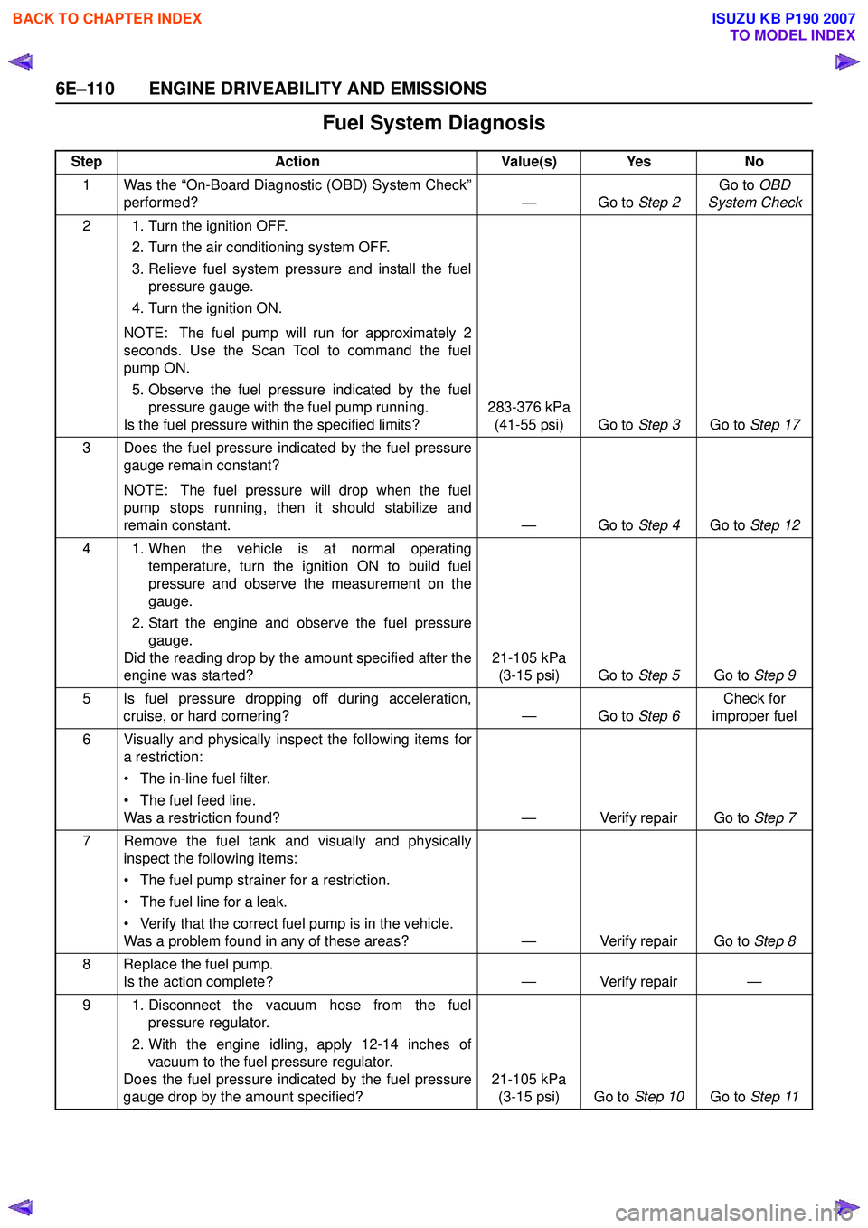
Fuel System Diagnosis
StepAction Value(s) Yes No
1 Was the “On-Board Diagnostic (OBD) System Check” performed? — Go to Step 2Go to
OBD
System Check
2 1. Turn the ignition OFF. 2. Turn the air conditioning system OFF.
3. Relieve fuel system pressure and install the fuel pressure gauge.
4. Turn the ignition ON.
NOTE: The fuel pump will run for approximately 2
seconds. Use the Scan Tool to command the fuel
pump ON.
5. Observe the fuel pressure indicated by the fuel pressure gauge with the fuel pump running.
Is the fuel pressure within the specified limits? 283-376 kPa
(41-55 psi) Go to Step 3Go to Step 17
3 Does the fuel pressure indicated by the fuel pressure gauge remain constant?
NOTE: The fuel pressure will drop when the fuel
pump stops running, then it should stabilize and
remain constant. — Go to Step 4Go to Step 12
4 1. When the vehicle is at normal operating temperature, turn the ignition ON to build fuel
pressure and observe the measurement on the
gauge.
2. Start the engine and observe the fuel pressure gauge.
Did the reading drop by the amount specified after the
engine was started? 21-105 kPa
(3-15 psi) Go to Step 5Go to Step 9
5 Is fuel pressure dropping off during acceleration, cruise, or hard cornering? — Go to Step 6Check for
improper fuel
6 Visually and physically inspect the following items for a restriction:
• The in-line fuel filter.
• The fuel feed line.
Was a restriction found? — Verify repair Go to Step 7
7 Remove the fuel tank and visually and physically inspect the following items:
• The fuel pump strainer for a restriction.
• The fuel line for a leak.
• Verify that the correct fuel pump is in the vehicle.
Was a problem found in any of these areas? — Verify repair Go to Step 8
8 Replace the fuel pump. Is the action complete? — Verify repair —
9 1. Disconnect the vacuum hose from the fuel pressure regulator.
2. With the engine idling, apply 12-14 inches of vacuum to the fuel pressure regulator.
Does the fuel pressure indicated by the fuel pressure
gauge drop by the amount specified? 21-105 kPa
(3-15 psi) Go to Step 10Go to Step 11
BACK TO CHAPTER INDEX
TO MODEL INDEX
ISUZU KB P190 2007
Page 2384 of 6020
6E–214 ENGINE DRIVEABILITY AND EMISSIONS
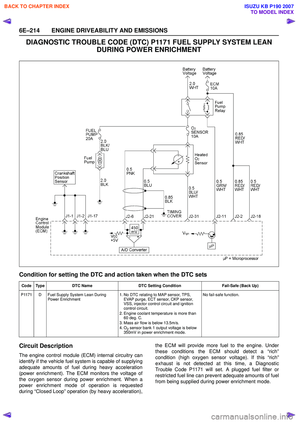
DIAGNOSTIC TROUBLE CODE (DTC) P1171 FUEL SUPPLY SYSTEM LEAN DURING POWER ENRICHMENT
Condition for setting the DTC and action taken when the DTC sets
Circuit Description
The engine control module (ECM) internal circuitry can
identify if the vehicle fuel system is capable of supplying
adequate amounts of fuel during heavy acceleration
(power enrichment). The ECM monitors the voltage of
the oxygen sensor during power enrichment. When a
power enrichment mode of operation is requested
during “Closed Loop” operation (by heavy acceleration), the ECM will provide more fuel to the engine. Under
these conditions the ECM should detect a “rich”
condition (high oxygen sensor voltage). If this “rich”
exhaust is not detected at this time, a Diagnostic
Trouble Code P1171 will set. A plugged fuel filter or
restricted fuel line can prevent adequate amounts of fuel
from being supplied during power enrichment mode.
Code Type DTC Name DTC Setting Condition Fail-Safe (Back Up)
P1171 D Fuel Supply System Lean During Power Enrichment 1. No DTC relating to MAP sensor, TPS,
EVAP purge, ECT sensor, CKP sensor,
VSS, injector control circuit and ignition
control circuit.
2. Engine coolant temperature is more than 60 deg. C.
3. Mass air flow is below 13.5m/s.
4. O
2 sensor bank 1 output voltage is below
350mV in power enrichment mode. No fail-safe function.
BACK TO CHAPTER INDEX
TO MODEL INDEX
ISUZU KB P190 2007
Page 2419 of 6020
ENGINE DRIVEABILITY AND EMISSIONS 6E–249
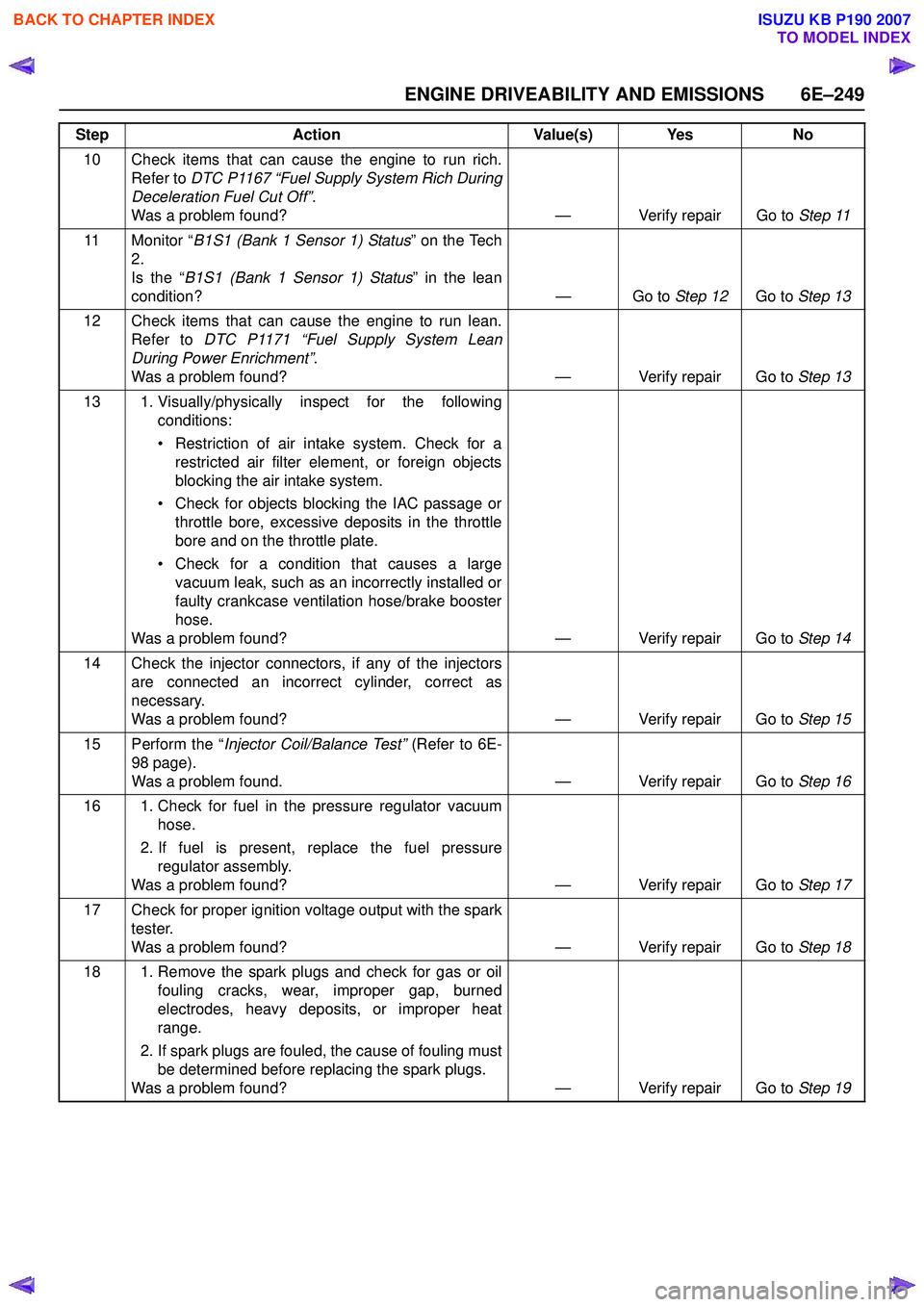
10 Check items that can cause the engine to run rich.Refer to DTC P1167 “Fuel Supply System Rich During
Deceleration Fuel Cut Off” .
Was a problem found? — Verify repair Go to Step 11
11 Monitor “ B1S1 (Bank 1 Sensor 1) Status ” on the Tech
2.
Is the “ B1S1 (Bank 1 Sensor 1) Status ” in the lean
condition? — Go to Step 12Go to Step 13
12 Check items that can cause the engine to run lean. Refer to DTC P1171 “Fuel Supply System Lean
During Power Enrichment” .
Was a problem found? — Verify repair Go to Step 13
13 1. Visually/physically inspect for the following conditions:
• Restriction of air intake system. Check for a restricted air filter element, or foreign objects
blocking the air intake system.
• Check for objects blocking the IAC passage or throttle bore, excessive deposits in the throttle
bore and on the throttle plate.
• Check for a condition that causes a large vacuum leak, such as an incorrectly installed or
faulty crankcase ventilation hose/brake booster
hose.
Was a problem found? — Verify repair Go to Step 14
14 Check the injector connectors, if any of the injectors are connected an incorrect cylinder, correct as
necessary.
Was a problem found? — Verify repair Go to Step 15
15 Perform the “ Injector Coil/Balance Test” (Refer to 6E-
98 page).
Was a problem found. — Verify repair Go to Step 16
16 1. Check for fuel in the pressure regulator vacuum hose.
2. If fuel is present, replace the fuel pressure regulator assembly.
Was a problem found? — Verify repair Go to Step 17
17 Check for proper ignition voltage output with the spark tester.
Was a problem found? — Verify repair Go to Step 18
18 1. Remove the spark plugs and check for gas or oil fouling cracks, wear, improper gap, burned
electrodes, heavy deposits, or improper heat
range.
2. If spark plugs are fouled, the cause of fouling must be determined before replacing the spark plugs.
Was a problem found? — Verify repair Go to Step 19
Step
Action Value(s) Yes No
BACK TO CHAPTER INDEX
TO MODEL INDEX
ISUZU KB P190 2007
Page 2421 of 6020
ENGINE DRIVEABILITY AND EMISSIONS 6E–251
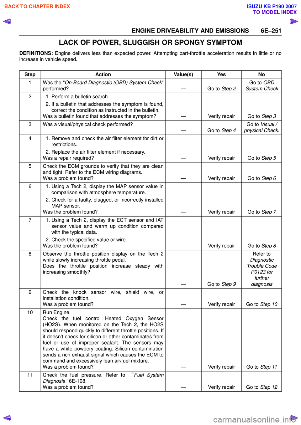
LACK OF POWER, SLUGGISH OR SPONGY SYMPTOM
DEFINITIONS: Engine delivers less than expected power. Attempting part-throttle acceleration results in little or no
increase in vehicle speed.
Step Action Value(s) Yes No
1 Was the “ On-Board Diagnostic (OBD) System Check ”
performed? — Go to Step 2Go to
OBD
System Check
2 1. Perform a bulletin search. 2. If a bulletin that addresses the symptom is found,correct the condition as instructed in the bulletin.
Was a bulletin found that addresses the symptom? — Verify repair Go to Step 3
3 Was a visual/physical check performed? —Go to Step 4Go to
Visual /
physical Check .
4 1. Remove and check the air filter element for dirt or restrictions.
2. Replace the air filter element if necessary.
Was a repair required? — Verify repair Go to Step 5
5 Check the ECM grounds to verify that they are clean and tight. Refer to the ECM wiring diagrams.
Was a problem found? — Verify repair Go to Step 6
6 1. Using a Tech 2, display the MAP sensor value in comparison with atmosphere temperature.
2. Check for a faulty, plugged, or incorrectly installed MAP sensor.
Was the problem found? — Verify repair Go to Step 7
7 1. Using a Tech 2, display the ECT sensor and IAT sensor value and warm up condition compared
with the typical data.
2. Check the specified value or wire.
Was the problem found? — Verify repair Go to Step 8
8 Observe the throttle position display on the Tech 2 while slowly increasing throttle pedal.
Does the throttle position increase steady with
increasing smoothly?
—Go to Step 9Refer to
Diagnostic
Trouble Code P0123 for further
diagnosis
9 Check the knock sensor wire, shield wire, or installation condition.
Was a problem found? — Verify repair Go to Step 10
10 Run Engine. Check the fuel control Heated Oxygen Sensor
(HO2S). When monitored on the Tech 2, the HO2S
should respond quickly to different throttle positions. If
it doesn’t check for silicon or other contaminates from
fuel or use of improper sealant. The sensors may
have a white powdery coating. Silicon contamination
sends a rich exhaust signal which causes the ECM to
command and excessively lean air/fuel mixture.
Was a problem found? — Verify repair Go to Step 11
11 Check the fuel pressure. Refer to “Fuel System
Diagnosis
” 6E-108.
Was a problem found? — Verify repair Go to Step 12
BACK TO CHAPTER INDEX
TO MODEL INDEX
ISUZU KB P190 2007
Page 2426 of 6020
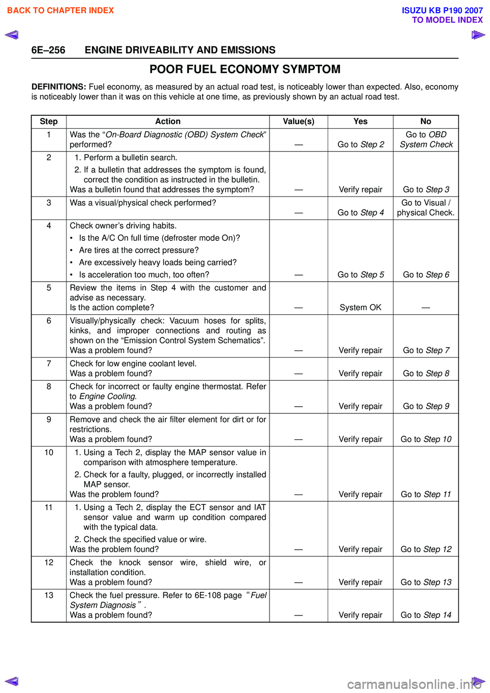
6E–256 ENGINE DRIVEABILITY AND EMISSIONS
POOR FUEL ECONOMY SYMPTOM
DEFINITIONS: Fuel economy, as measured by an actual road test, is noticeably lower than expected. Also, economy
is noticeably lower than it was on this vehicle at one time, as previously shown by an actual road test.
Step Action Value(s) Yes No
1 Was the “ On-Board Diagnostic (OBD) System Check ”
performed? — Go to Step 2Go to
OBD
System Check
2 1. Perform a bulletin search. 2. If a bulletin that addresses the symptom is found,correct the condition as instructed in the bulletin.
Was a bulletin found that addresses the symptom? — Verify repair Go to Step 3
3 Was a visual/physical check performed? —Go to Step 4Go to Visual /
physical Check.
4 Check owner’s driving habits. • Is the A/C On full time (defroster mode On)?
• Are tires at the correct pressure?
• Are excessively heavy loads being carried?
• Is acceleration too much, too often? — Go to Step 5Go to Step 6
5 Review the items in Step 4 with the customer and advise as necessary.
Is the action complete? — System OK —
6 Visually/physically check: Vacuum hoses for splits, kinks, and improper connections and routing as
shown on the “Emission Control System Schematics”.
Was a problem found? — Verify repair Go to Step 7
7 Check for low engine coolant level. Was a problem found? — Verify repair Go to Step 8
8 Check for incorrect or faulty engine thermostat. Refer to Engine Cooling .
Was a problem found? — Verify repair Go to Step 9
9 Remove and check the air filter element for dirt or for restrictions.
Was a problem found? — Verify repair Go to Step 10
10 1. Using a Tech 2, display the MAP sensor value in comparison with atmosphere temperature.
2. Check for a faulty, plugged, or incorrectly installed MAP sensor.
Was the problem found? — Verify repair Go to Step 11
11 1. Using a Tech 2, display the ECT sensor and IAT sensor value and warm up condition compared
with the typical data.
2. Check the specified value or wire.
Was the problem found? — Verify repair Go to Step 12
12 Check the knock sensor wire, shield wire, or installation condition.
Was a problem found? — Verify repair Go to Step 13
13 Check the fuel pressure. Refer to 6E-108 page “Fuel
System Diagnosis
” .
Was a problem found? — Verify repair Go to Step 14
BACK TO CHAPTER INDEX
TO MODEL INDEX
ISUZU KB P190 2007
Page 2442 of 6020
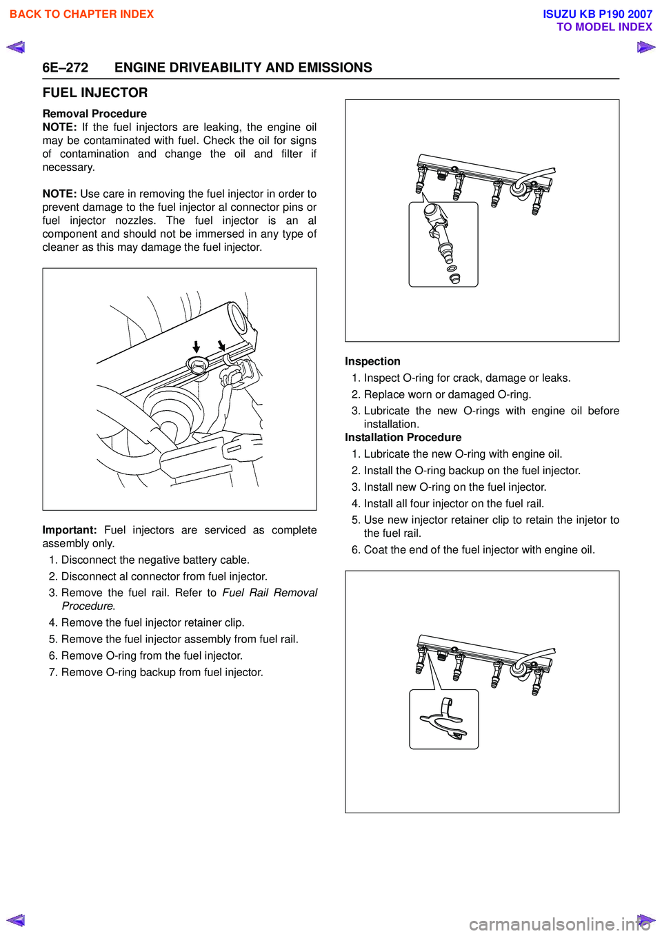
6E–272 ENGINE DRIVEABILITY AND EMISSIONS
FUEL INJECTOR
Removal Procedure
NOTE: If the fuel injectors are leaking, the engine oil
may be contaminated with fuel. Check the oil for signs
of contamination and change the oil and filter if
necessary.
NOTE: Use care in removing the fuel injector in order to
prevent damage to the fuel injector al connector pins or
fuel injector nozzles. The fuel injector is an al
component and should not be immersed in any type of
cleaner as this may damage the fuel injector.
Important: Fuel injectors are serviced as complete
assembly only.
1. Disconnect the negative battery cable.
2. Disconnect al connector from fuel injector.
3. Remove the fuel rail. Refer to Fuel Rail Removal
Procedure .
4. Remove the fuel injector retainer clip.
5. Remove the fuel injector assembly from fuel rail.
6. Remove O-ring from the fuel injector.
7. Remove O-ring backup from fuel injector. Inspection
1. Inspect O-ring for crack, damage or leaks.
2. Replace worn or damaged O-ring.
3. Lubricate the new O-rings with engine oil before installation.
Installation Procedure
1. Lubricate the new O-ring with engine oil.
2. Install the O-ring backup on the fuel injector.
3. Install new O-ring on the fuel injector.
4. Install all four injector on the fuel rail.
5. Use new injector retainer clip to retain the injetor to the fuel rail.
6. Coat the end of the fuel injector with engine oil.
BACK TO CHAPTER INDEX
TO MODEL INDEX
ISUZU KB P190 2007
Page 2771 of 6020
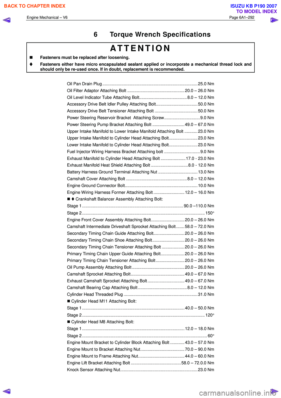
Engine Mechanical – V6 Page 6A1–292
6 Torque Wrench Specifications
ATTENTION
�„
�„�„
�„
Fasteners must be replaced after loosening.
Fasteners either have micro encapsulated sealant applied or incorporate a mechanical thread lock and
should only be re-used once. If in doubt, replacement is recommended.
Oil Pan Drain Plug ................................................................................ 25.0 Nm
Oil Filter Adaptor Attaching Bolt ................................................ 20.0 – 26.0 Nm
Oil Level Indicator Tube Attaching Bolt........................................ 8.0 – 12.0 Nm
Accessory Drive Belt Idler Pulley Attaching Bolt................................... 50.0 Nm
Accessory Drive Belt Tensioner Attaching Bolt .................................... 50.0 Nm
Power Steering Reservoir Bracket Attaching Screw.............................. 9.0 Nm
Power Steering Pump Bracket Attaching Bolt ........................... 49.0 – 67.0 Nm
Upper Intake Manifold to Lower Intake Manifold Attaching Bolt ........... 23.0 Nm
Upper Intake Manifold to Cylinder Head Attaching Bolt........................ 23.0 Nm
Lower Intake Manifold to Cylinder Head Attaching Bolt........................ 23.0 Nm
Fuel Injector Wiring Harness Bracket Attaching bolt .............................. 9.0 Nm
Exhaust Manifold to Cylinder Head Attaching Bolt ..................... 17.0 - 23.0 Nm
Exhaust Manifold Heat Shield Attaching Bolt ............................... 8.0 - 12.0 Nm
Battery Harness Ground Terminal Attaching Nut ................................. 13.0 Nm
Camshaft Cover Attaching Bolt ................................................... 8.0 – 12.0 Nm
Engine Ground Connector Bolt............................................................. 10.0 Nm
Engine Wiring Harness Former Attaching Bolt .......................... 12.0 – 16.0 Nm
�„ Crankshaft Balancer Assembly Attaching Bolt:
Stage 1 ..................................................................................... 90.0 –110.0 Nm
Stage 2 ....................................................................................................... 150 °
Engine Front Cover Assembly Attaching Bolt ............................ 20.0 – 26.0 Nm
Camshaft Intermediate Driveshaft Sprocket Attaching Bolt ....... 58.0 – 72.0 Nm
Secondary Timing Chain Guide Attaching Bolt.......................... 20.0 – 26.0 Nm
Secondary Timing Chain Shoe Attaching Bolt ........................... 20.0 – 26.0 Nm
Secondary Timing Chain Tensioner Attaching Bolt ................... 20.0 – 26.0 Nm
Primary Timing Chain Upper Guide Attaching Bolt.................... 20.0 – 26.0 Nm
Primary Timing Chain Tensioner Attaching Bolt ........................ 20.0 – 26.0 Nm
Oil Pump Assembly Attaching Bolt ............................................ 20.0 – 26.0 Nm
Camshaft Sprocket Attaching Bolt ............................................. 49.0 – 67.0 Nm
Exhaust Camshaft Sprocket Attaching Bolt ............................... 49.0 – 67.0 Nm
Camshaft Bearing Cap Attaching Bolt ......................................... 8.0 – 12.0 Nm
Cylinder Head Threaded Plug .............................................................. 31.0 Nm
�„ Cylinder Head M11 Attaching Bolt:
Stage 1 ...................................................................................... 40.0 – 50.0 Nm
Stage 2 ....................................................................................................... 120 °
�„ Cylinder Head M8 Attaching Bolt:
Stage 1 ...................................................................................... 12.0 – 18.0 Nm
Stage 2 ......................................................................................................... 60 °
Engine Mount Bracket to Cylinder Block Attaching Bolt ............ 43.0 – 57.0 Nm
Engine Mount to Bracket Attaching Nut ..................................... 70.0 – 90.0 Nm
Engine Mount to Frame Attaching Nut....................................... 44.0 – 60.0 Nm
Engine Lift Bracket Attaching Bolt .......................................... 58.0 – 72.0.0 Nm
Knock Sensor Attaching Nut................................................................. 23.0 Nm
BACK TO CHAPTER INDEX
TO MODEL INDEX
ISUZU KB P190 2007
Page 3128 of 6020
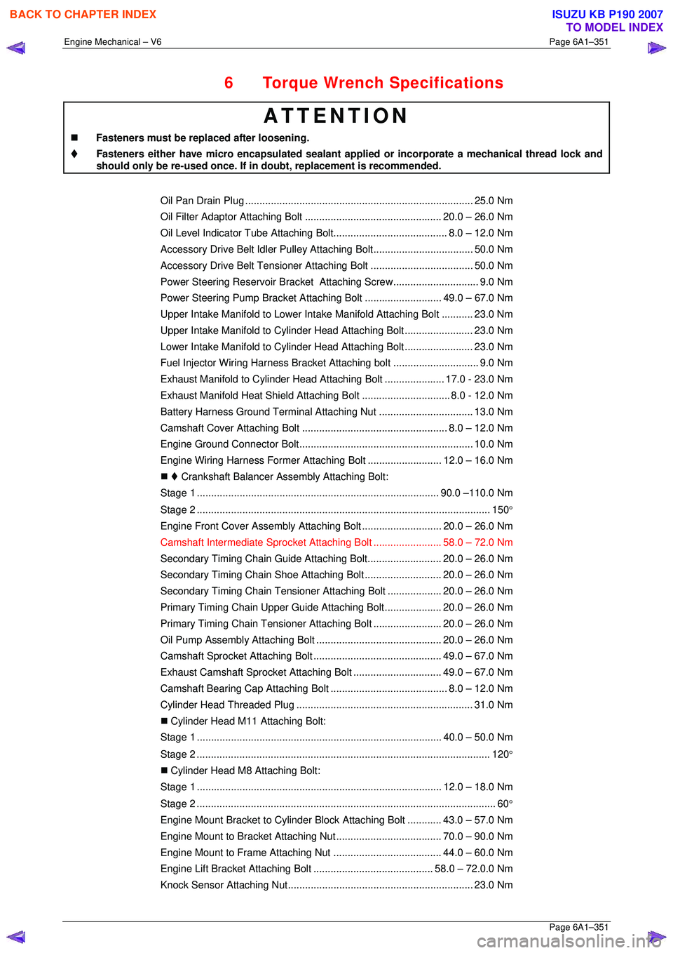
Engine Mechanical – V6 Page 6A1–351
Page 6A1–351
6 Torque Wrench Specifications
ATTENTION
�„ Fasteners must be replaced after loosening.
Fasteners either have micro encapsulated sealant a pplied or incorporate a mechanical thread lock and
should only be re-used once. If in doubt, replacement is recommended.
Oil Pan Drain Plug ................................................................................ 25.0 Nm
Oil Filter Adaptor Attach ing Bolt................................................ 20.0 – 26.0 Nm
Oil Level Indicator Tube Atta ching Bolt........................................ 8.0 – 12.0 Nm
Accessory Drive Belt Idler Pu lley Attaching Bolt................................... 50.0 Nm
Accessory Drive Belt Tensio ner Attaching Bolt .................................... 50.0 Nm
Power Steering Reserv oir Bracket Attaching Screw.............................. 9.0 Nm
Power Steering Pump Bracket A ttaching Bolt ........................... 49. 0 – 67.0 Nm
Upper Intake Manifold to Lower Intake Manifold Attaching Bolt ........... 23.0 Nm
Upper Intake Manifold to Cylinder Head Attaching Bolt........................ 23.0 Nm
Lower Intake Manifold to Cylind er Head Attaching Bolt........................ 23.0 Nm
Fuel Injector Wiring Harness Br acket Attaching bolt .............................. 9. 0 Nm
Exhaust Manifold to Cylinder He ad Attaching Bolt..................... 17.0 - 23.0 Nm
Exhaust Manifold Heat Shield Attaching Bolt ............................... 8.0 - 12.0 Nm
Battery Harness Ground Terminal Attaching Nut ................................. 13. 0 Nm
Camshaft Cover Attachi ng Bolt................................................... 8.0 – 12.0 Nm
Engine Ground Connec tor Bolt............................................................. 10.0 Nm
Engine Wiring Harness Former A ttaching Bolt .......................... 12.0 – 16.0 Nm
�„ Crankshaft Balancer A ssembly Attaching Bolt:
Stage 1 ..................................................................................... 90.0 –110.0 Nm
Stage 2 ....................................................................................................... 150 °
Engine Front Cover Assembly A ttaching Bolt ............................ 20. 0 – 26.0 Nm
Camshaft Intermediate Sprocket Attaching Bolt ........................ 58. 0 – 72.0 Nm
Secondary Timing Chai n Guide Attaching Bolt.......................... 20.0 – 26.0 Nm
Secondary Timing Chai n Shoe Attaching Bolt ........................... 20.0 – 26.0 Nm
Secondary Timing Chain Tensioner Attachi ng Bolt ................... 20.0 – 26.0 Nm
Primary Timing Chain Upper Gui de Attaching Bolt.................... 20.0 – 26.0 Nm
Primary Timing Chain Tensioner Attaching Bolt........................ 20. 0 – 26.0 Nm
Oil Pump Assembly Attach ing Bolt............................................ 20.0 – 26.0 Nm
Camshaft Sprocket Attachi ng Bolt............................................. 49.0 – 67.0 Nm
Exhaust Camshaft Sprocket Atta ching Bolt............................... 49.0 – 67.0 Nm
Camshaft Bearing Cap Attach ing Bolt......................................... 8.0 – 12.0 Nm
Cylinder Head Thr eaded Plug.............................................................. 31.0 Nm
�„ Cylinder Head M11 Attaching Bolt:
Stage 1 ...................................................................................... 40.0 – 50.0 Nm
Stage 2 ....................................................................................................... 120 °
�„ Cylinder Head M8 Attaching Bolt:
Stage 1 ...................................................................................... 12.0 – 18.0 Nm
Stage 2 ......................................................................................................... 60 °
Engine Mount Bracket to Cylinder Bl ock Attaching Bolt............ 43.0 – 57.0 Nm
Engine Mount to Bracket Atta ching Nut..................................... 70.0 – 90.0 Nm
Engine Mount to Frame Atta ching Nut...................................... 44.0 – 60.0 Nm
Engine Lift Bracket Attachi ng Bolt.......................................... 58.0 – 72.0.0 Nm
Knock Sensor Attach ing Nut................................................................. 23.0 Nm
BACK TO CHAPTER INDEX
TO MODEL INDEX
ISUZU KB P190 2007