2007 ISUZU KB P190 fuel filter
[x] Cancel search: fuel filterPage 3314 of 6020
Engine Management – V6 – Diagnostics Page 6C1-2–36
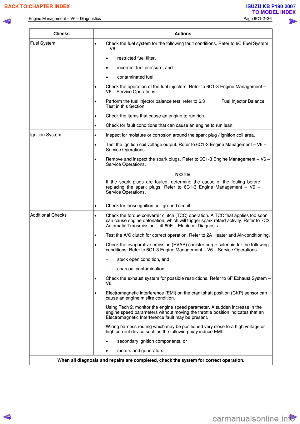
Checks Actions
Fuel System
• Check the fuel system for the following fault conditions. Refer to 6C Fuel System
– V6.
• restricted fuel filter,
• incorrect fuel pressure, and
• contaminated fuel.
• Check the operation of the fuel injectors. Refer to 6C1-3 Engine Management –
V6 – Service Operations.
• Perform the fuel injector balance test, refer to 6.3 Fuel Injector Balance
Test in this Section.
• Check the items that cause an engine to run rich.
• Check for fault conditions that can cause an engine to run lean.
Ignition System
• Inspect for moisture or corrosion around the spark plug / ignition coil area.
• Test the ignition coil voltage output. Refer to 6C1-3 Engine Management – V6 –
Service Operations.
• Remove and inspect the spark plugs. Refer to 6C1-3 Engine Management – V6 –
Service Operations.
NOTE
If the spark plugs are fouled, determine the cause of the fouling before
replacing the spark plugs. Refer to 6C1-3 Engine Management – V6 –
Service Operations.
• Check for loose ignition coil ground circuit.
Additional Checks
• Check the torque converter clutch (TCC) operation. A TCC that applies too soon
can cause engine detonation, which will trigger spark retard activity. Refer to 7C2
Automatic Transmission – 4L60E – Electrical Diagnosis.
• Test the A/C clutch for correct operation. Refer to 2A Heater and Air-conditioning.
• Check the evaporative emission (EVAP) canister purge solenoid for the following
conditions: Refer to 6C1-3 Engine Management – V6 – Service Operations.
− stuck open condition, and
− charcoal contamination.
• Check the exhaust system for possible restrictions. Refer to 6F Exhaust System –
V6.
• Electromagnetic interference (EMI) on the crankshaft position (CKP) sensor can
cause an engine misfire condition.
Using Tech 2, monitor the engine speed parameter. A sudden increase in the engine speed parameters without moving the throttle position indicates that an
Electromagnetic Interference fault may be present.
W iring harness routing which may be positioned very close to a high voltage or high current device such as the following may induce EMI:
• secondary ignition components, or
• motors and generators.
When all diagnosis and repairs are completed, check the system for correct operation.
BACK TO CHAPTER INDEX
TO MODEL INDEX
ISUZU KB P190 2007
Page 3324 of 6020
Engine Management – V6 – Diagnostics Page 6C1-2–46
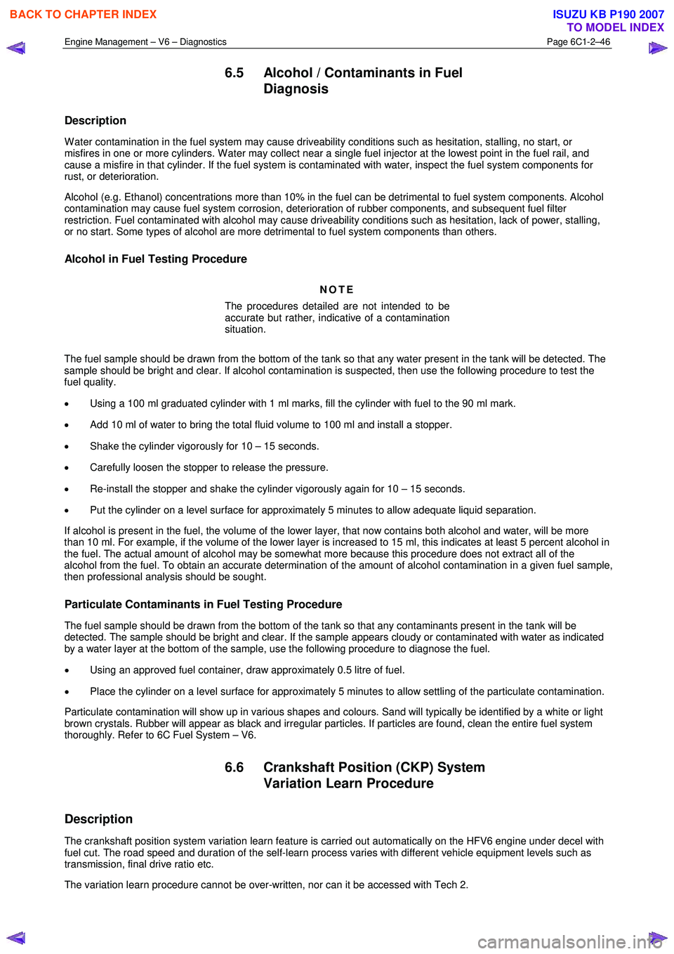
6.5 Alcohol / Contaminants in Fuel
Diagnosis
Description
W ater contamination in the fuel system may cause driveability conditions such as hesitation, stalling, no start, or
misfires in one or more cylinders. W ater may collect near a single fuel injector at the lowest point in the fuel rail, and
cause a misfire in that cylinder. If the fuel system is contaminated with water, inspect the fuel system components for
rust, or deterioration.
Alcohol (e.g. Ethanol) concentrations more than 10% in the fuel can be detrimental to fuel system components. Alcohol
contamination may cause fuel system corrosion, deterioration of rubber components, and subsequent fuel filter
restriction. Fuel contaminated with alcohol may cause driveability conditions such as hesitation, lack of power, stalling,
or no start. Some types of alcohol are more detrimental to fuel system components than others.
Alcohol in Fuel Testing Procedure
NOTE
The procedures detailed are not intended to be
accurate but rather, indicative of a contamination
situation.
The fuel sample should be drawn from the bottom of the tank so that any water present in the tank will be detected. The
sample should be bright and clear. If alcohol contamination is suspected, then use the following procedure to test the
fuel quality.
• Using a 100 ml graduated cylinder with 1 ml marks, fill the cylinder with fuel to the 90 ml mark.
• Add 10 ml of water to bring the total fluid volume to 100 ml and install a stopper.
• Shake the cylinder vigorously for 10 – 15 seconds.
• Carefully loosen the stopper to release the pressure.
• Re-install the stopper and shake the cylinder vigorously again for 10 – 15 seconds.
• Put the cylinder on a level surface for approximately 5 minutes to allow adequate liquid separation.
If alcohol is present in the fuel, the volume of the lower layer, that now contains both alcohol and water, will be more
than 10 ml. For example, if the volume of the lower layer is increased to 15 ml, this indicates at least 5 percent alcohol in
the fuel. The actual amount of alcohol may be somewhat more because this procedure does not extract all of the
alcohol from the fuel. To obtain an accurate determination of the amount of alcohol contamination in a given fuel sample,
then professional analysis should be sought.
Particulate Contaminants in Fuel Testing Procedure
The fuel sample should be drawn from the bottom of the tank so that any contaminants present in the tank will be
detected. The sample should be bright and clear. If the sample appears cloudy or contaminated with water as indicated
by a water layer at the bottom of the sample, use the following procedure to diagnose the fuel.
• Using an approved fuel container, draw approximately 0.5 litre of fuel.
• Place the cylinder on a level surface for approximately 5 minutes to allow settling of the particulate contamination.
Particulate contamination will show up in various shapes and colours. Sand will typically be identified by a white or light
brown crystals. Rubber will appear as black and irregular particles. If particles are found, clean the entire fuel system
thoroughly. Refer to 6C Fuel System – V6.
6.6 Crankshaft Position (CKP) System
Variation Learn Procedure
Description
The crankshaft position system variation learn feature is carried out automatically on the HFV6 engine under decel with
fuel cut. The road speed and duration of the self-learn process varies with different vehicle equipment levels such as
transmission, final drive ratio etc.
The variation learn procedure cannot be over-written, nor can it be accessed with Tech 2.
BACK TO CHAPTER INDEX
TO MODEL INDEX
ISUZU KB P190 2007
Page 3385 of 6020
Engine Management – V6 – Diagnostics Page 6C1-2–107
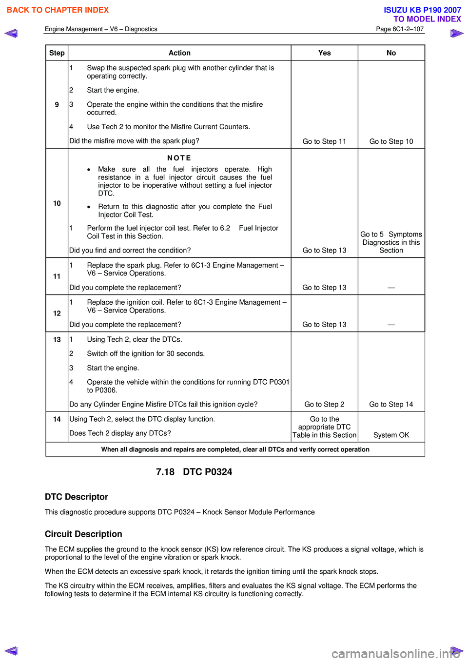
Step Action Yes No
9 1 Swap the suspected spark plug with another cylinder that is
operating correctly.
2 Start the engine.
3 Operate the engine within the conditions that the misfire occurred.
4 Use Tech 2 to monitor the Misfire Current Counters.
Did the misfire move with the spark plug? Go to Step 11 Go to Step 10
10 NOTE
• Make sure all the fuel injectors operate. High
resistance in a fuel injector circuit causes the fuel
injector to be inoperative without setting a fuel injector
DTC.
• Return to this diagnostic after you complete the Fuel
Injector Coil Test.
1 Perform the fuel injector coil test. Refer to 6.2 Fuel Injector Coil Test in this Section.
Did you find and correct the condition? Go to Step 13 Go to 5 Symptoms
Diagnostics in this Section
11 1 Replace the spark plug. Refer to 6C1-3 Engine Management –
V6 – Service Operations.
Did you complete the replacement? Go to Step 13 —
12 1 Replace the ignition coil. Refer to 6C1-3 Engine Management –
V6 – Service Operations.
Did you complete the replacement? Go to Step 13 —
13 1 Using Tech 2, clear the DTCs.
2 Switch off the ignition for 30 seconds.
3 Start the engine.
4 Operate the vehicle within the conditions for running DTC P0301 to P0306.
Do any Cylinder Engine Misfire DTCs fail this ignition cycle? Go to Step 2 Go to Step 14
14 Using Tech 2, select the DTC display function.
Does Tech 2 display any DTCs? Go to the
appropriate DTC
Table in this Section System OK
When all diagnosis and repairs are completed, clear all DTCs and verify correct operation
7.18 DTC P0324
DTC Descriptor
This diagnostic procedure supports DTC P0324 – Knock Sensor Module Performance
Circuit Description
The ECM supplies the ground to the knock sensor (KS) low reference circuit. The KS produces a signal voltage, which is
proportional to the level of the engine vibration or spark knock.
W hen the ECM detects an excessive spark knock, it retards the ignition timing until the spark knock stops.
The KS circuitry within the ECM receives, amplifies, filters and evaluates the KS signal voltage. The ECM performs the
following tests to determine if the ECM internal KS circuitry is functioning correctly.
BACK TO CHAPTER INDEX
TO MODEL INDEX
ISUZU KB P190 2007
Page 3468 of 6020
Engine Management – V6 – Diagnostics Page 6C1-2–190
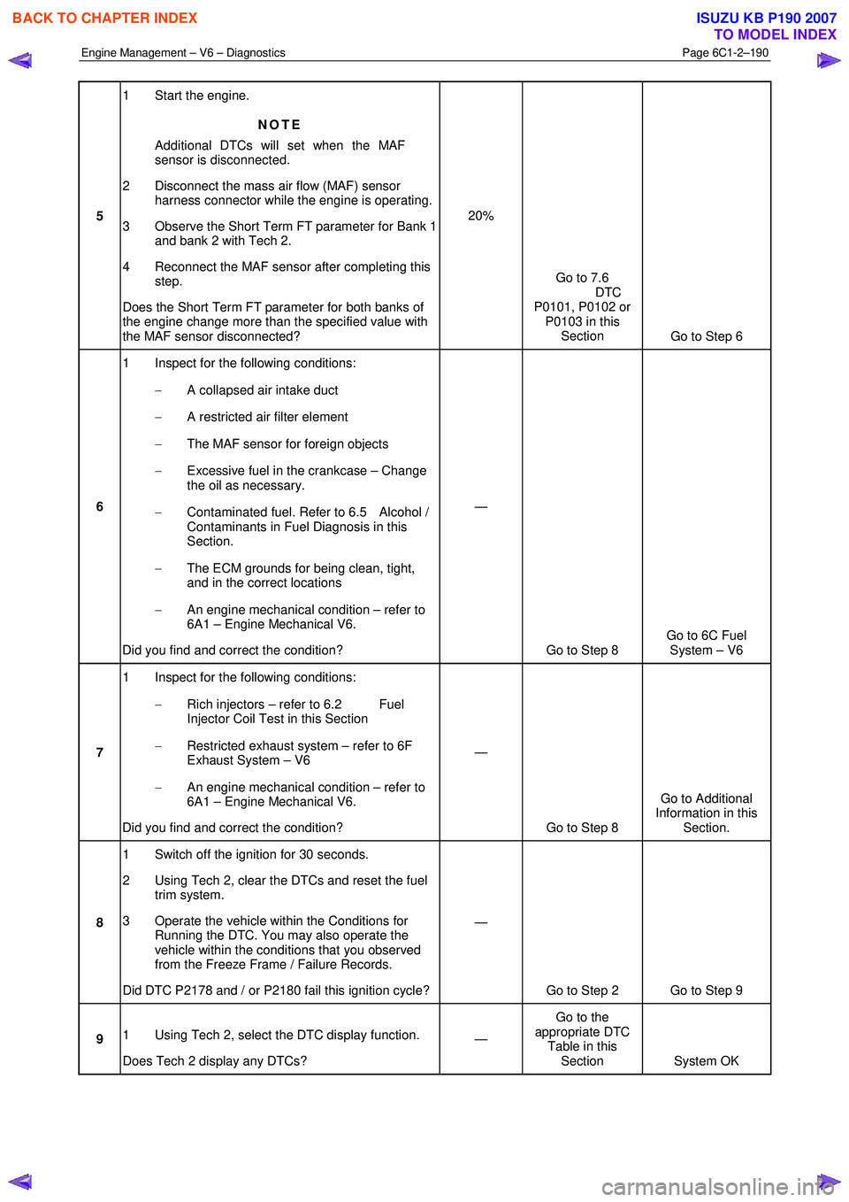
5 1 Start the engine.
NOTE
Additional DTCs will set when the MAF
sensor is disconnected.
2 Disconnect the mass air flow (MAF) sensor harness connector while the engine is operating.
3 Observe the Short Term FT parameter for Bank 1 and bank 2 with Tech 2.
4 Reconnect the MAF sensor after completing this step.
Does the Short Term FT parameter for both banks of
the engine change more than the specified value with
the MAF sensor disconnected? 20%
Go to 7.6
DTC
P0101, P0102 or P0103 in this Section Go to Step 6
6 1 Inspect for the following conditions:
− A collapsed air intake duct
− A restricted air filter element
− The MAF sensor for foreign objects
− Excessive fuel in the crankcase – Change
the oil as necessary.
− Contaminated fuel. Refer to 6.5 Alcohol /
Contaminants in Fuel Diagnosis in this
Section.
− The ECM grounds for being clean, tight,
and in the correct locations
− An engine mechanical condition – refer to
6A1 – Engine Mechanical V6.
Did you find and correct the condition? —
Go to Step 8 Go to 6C Fuel
System – V6
7 1 Inspect for the following conditions:
− Rich injectors – refer to 6.2 Fuel
Injector Coil Test in this Section
− Restricted exhaust system – refer to 6F
Exhaust System – V6
− An engine mechanical condition – refer to
6A1 – Engine Mechanical V6.
Did you find and correct the condition? —
Go to Step 8 Go to Additional
Information in this Section.
8 1 Switch off the ignition for 30 seconds.
2 Using Tech 2, clear the DTCs and reset the fuel trim system.
3 Operate the vehicle within the Conditions for Running the DTC. You may also operate the
vehicle within the conditions that you observed
from the Freeze Frame / Failure Records.
Did DTC P2178 and / or P2180 fail this ignition cycle? —
Go to Step 2 Go to Step 9
9 1 Using Tech 2, select the DTC display function.
Does Tech 2 display any DTCs? —
Go to the
appropriate DTC Table in this Section System OK
BACK TO CHAPTER INDEX
TO MODEL INDEX
ISUZU KB P190 2007
Page 3474 of 6020
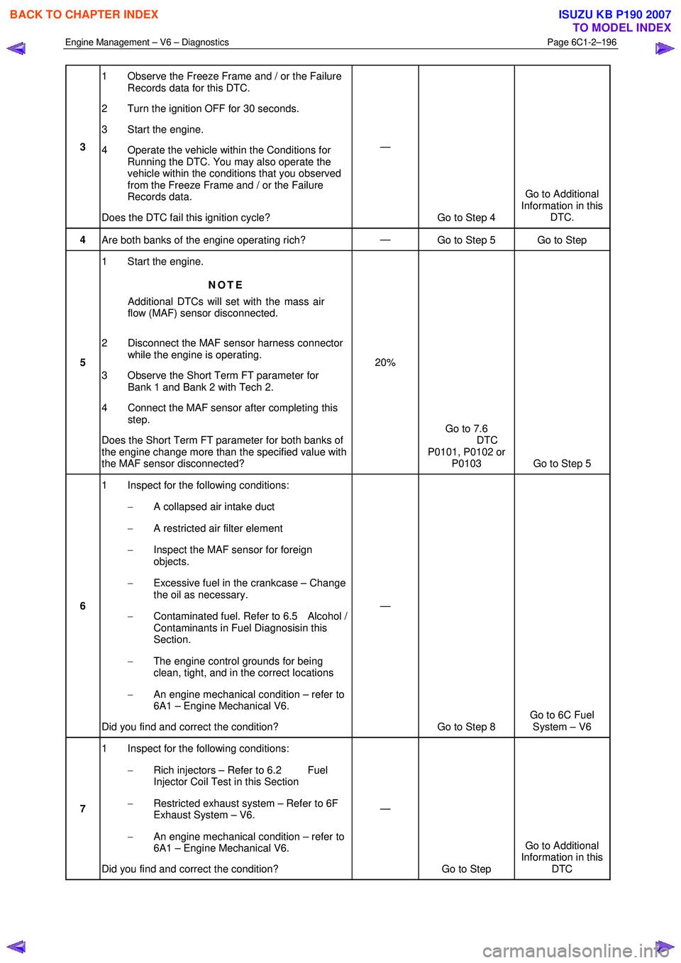
Engine Management – V6 – Diagnostics Page 6C1-2–196
3 1 Observe the Freeze Frame and / or the Failure
Records data for this DTC.
2 Turn the ignition OFF for 30 seconds.
3 Start the engine.
4 Operate the vehicle within the Conditions for Running the DTC. You may also operate the
vehicle within the conditions that you observed
from the Freeze Frame and / or the Failure
Records data.
Does the DTC fail this ignition cycle? —
Go to Step 4 Go to Additional
Information in this DTC.
4 Are both banks of the engine operating rich? —
Go to Step 5 Go to Step
5 1 Start the engine.
NOTE
Additional DTCs will set with the mass air
flow (MAF) sensor disconnected.
2 Disconnect the MAF sensor harness connector while the engine is operating.
3 Observe the Short Term FT parameter for Bank 1 and Bank 2 with Tech 2.
4 Connect the MAF sensor after completing this step.
Does the Short Term FT parameter for both banks of
the engine change more than the specified value with
the MAF sensor disconnected? 20%
Go to 7.6
DTC
P0101, P0102 or P0103 Go to Step 5
6 1 Inspect for the following conditions:
− A collapsed air intake duct
− A restricted air filter element
− Inspect the MAF sensor for foreign
objects.
− Excessive fuel in the crankcase – Change
the oil as necessary.
− Contaminated fuel. Refer to 6.5 Alcohol /
Contaminants in Fuel Diagnosisin this
Section.
− The engine control grounds for being
clean, tight, and in the correct locations
− An engine mechanical condition – refer to
6A1 – Engine Mechanical V6.
Did you find and correct the condition? —
Go to Step 8 Go to 6C Fuel
System – V6
7 1 Inspect for the following conditions:
− Rich injectors – Refer to 6.2 Fuel
Injector Coil Test in this Section
− Restricted exhaust system – Refer to 6F
Exhaust System – V6.
− An engine mechanical condition – refer to
6A1 – Engine Mechanical V6.
Did you find and correct the condition? —
Go to Step Go to Additional
Information in this DTC
BACK TO CHAPTER INDEX
TO MODEL INDEX
ISUZU KB P190 2007
Page 3530 of 6020
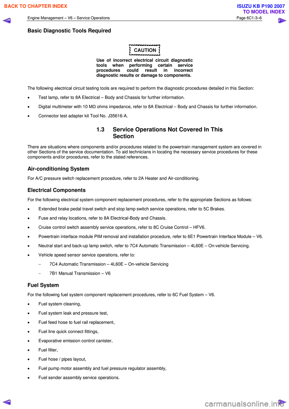
Engine Management – V6 – Service Operations Page 6C1-3–6
Basic Diagnostic Tools Required
Use of incorrect electrical circuit diagnostic
tools when performing certain service
procedures could result in incorrect
diagnostic results or damage to components.
The following electrical circuit testing tools are required to perform the diagnostic procedures detailed in this Section:
• Test lamp, refer to 8A Electrical – Body and Chassis for further information.
• Digital multimeter with 10 M Ω ohms impedance, refer to 8A Electrical – Body and Chassis for further information.
• Connector test adapter kit Tool No. J35616-A.
1.3 Service Operations Not Covered In This
Section
There are situations where components and/or procedures related to the powertrain management system are covered in
other Sections of the service documentation. To aid technicians in locating the necessary service procedures for these
components and/or procedures, refer to the stated references.
Air-conditioning System
For A/C pressure switch replacement procedure, refer to 2A Heater and Air-conditioning.
Electrical Components
For the following electrical system component replacement procedures, refer to the appropriate Sections as follows:
• Extended brake pedal travel switch and stop lamp switch service operations, refer to 5C Brakes.
• Fuse and relay locations, refer to 8A Electrical-Body and Chassis.
• Cruise control switch assembly service operations, refer to 8C Cruise Control – HFV6.
• Powertrain interface module PIM removal and installation procedure, refer to 6E1 Powertrain Interface Module – V6.
• Neutral start and back-up lamp switch, refer to 7C4 Automatic Transmission – 4L60E – On-vehicle Servicing.
• Vehicle speed sensor service operations, refer to:
− 7C4 Automatic Transmission – 4L60E – On-vehicle Servicing
− 7B1 Manual Transmission – V6
Fuel System
For the following fuel system component replacement procedures, refer to 6C Fuel System – V6.
• Fuel system cleaning,
• Fuel system leak and pressure test,
• Fuel feed hose to fuel rail replacement,
• Fuel line quick connect fittings,
• Evaporative emission control canister,
• Fuel filter,
• Fuel hose / pipes layout,
• Fuel pump motor assembly and fuel pressure regulator assembly,
• Fuel sender assembly service operations.
BACK TO CHAPTER INDEX
TO MODEL INDEX
ISUZU KB P190 2007
Page 4963 of 6020
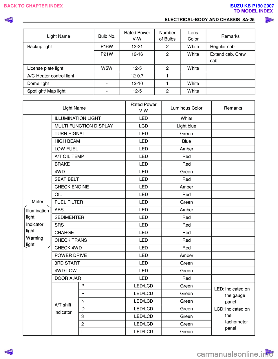
ELECTRICAL-BODY AND CHASSIS 8A-25
Light Name Bulb No. Rated Power
V-W Number
of Bulbs Lens
Color Remarks
P16W 12-21 2 W hite Regular cab Backup light
P21W 12-16 2 W hite Extend cab, Crew cab
License plate light W 5W 12-5 2 W hite
A/C-Heater control light - 12-0.7 1 -
Dome light - 12-10 1 W hite
Spotlight/ Map light - 12-5 2 W hite
Light Name Rated Power
V-W Luminous Color Remarks
ILLUMINATION
LIGHT LED W hite
MULTI FUNCTION DISPLAY LCD Light blue
TURN SIGNAL LED Green
HIGH BEAM LED Blue
LOW FUEL LED Amber
A/T OIL TEMP LED Red
BRAKE LED Red
4W D LED Green
SEAT BELT LED Red
CHECK ENGINE LED Amber
OIL LED Red
FUEL FILTER LED Green
ABS LED Amber
SEDIMENTER LED Red
SRS LED Red
CHARGE LED Red
CHECK TRANS LED Red
CHECK 4W D LED Red
POW ER DRIVE LED Amber
3RD START LED Green
4W D-LOW LED Green
DOOR AJAR LED Red
P LED/LCD Green
R LED/LCD Green
N LED/LCD Green
D LED/LCD Green
3 LED/LCD Green
2 LED/LCD Green
A/T shift
indicator
L LED/LCD Green LED: Indicated on
the gauge
panel
LCD: Indicated on the
tachometer
panel
Meter
Illumination
light,
Indicator
light,
W arning
light
BACK TO CHAPTER INDEX TO MODEL INDEXISUZU KB P190 2007
Page 5303 of 6020
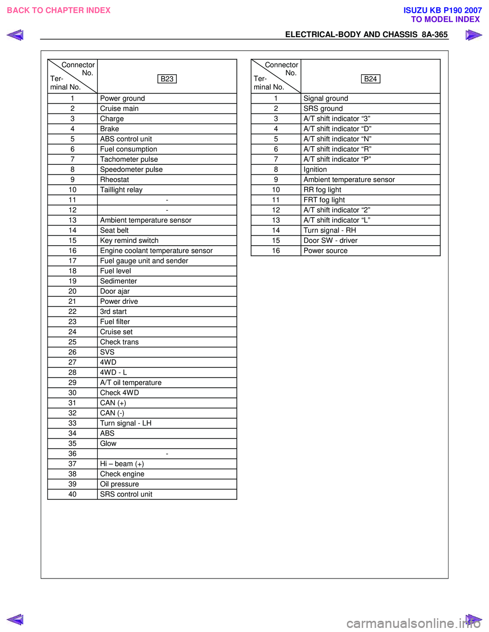
ELECTRICAL-BODY AND CHASSIS 8A-365
Connector
Ter- No.
minal No.
B23
1 Power ground
2 Cruise main
3 Charge
4 Brake
5 ABS control unit
6 Fuel consumption
7 Tachometer pulse
8 Speedometer pulse
9 Rheostat
10 Taillight relay
11 -
12 -
13 Ambient temperature sensor
14 Seat belt
15 Key remind switch
16 Engine coolant temperature sensor
17 Fuel gauge unit and sender
18 Fuel level
19 Sedimenter
20 Door ajar
21 Power drive
22 3rd start
23 Fuel filter
24 Cruise set
25 Check trans
26 SVS
27 4W D
28 4W D - L
29 A/T oil temperature
30 Check 4W D
31 CAN (+)
32 CAN (-)
33 Turn signal - LH
34 ABS
35 Glow
36 -
37 Hi – beam (+)
38 Check engine
39 Oil pressure
40 SRS control unit
Connector
Ter- No.
minal No.
B24
1 Signal ground
2 SRS ground
3 A/T shift indicator “3”
4 A/T shift indicator “D”
5 A/T shift indicator “N”
6 A/T shift indicator “R”
7 A/T shift indicator “P”
8 Ignition
9 Ambient temperature sensor
10 RR fog light
11 FRT fog light
12 A/T shift indicator “2”
13 A/T shift indicator “L”
14 Turn signal - RH
15 Door SW - driver
16 Power source
BACK TO CHAPTER INDEX TO MODEL INDEXISUZU KB P190 2007