Page 4559 of 6020

Torque: 6 N⋅
⋅⋅
⋅
m (0.6 kgf ⋅
⋅⋅
⋅
m/52 lb ⋅
⋅⋅
⋅
in)
• Remove the holding fixture from the transmission case.
RTW 47ASH001001")
7A4-82 UNIT REPAIR (JR405E)
Torque: 6 N⋅
⋅⋅
⋅
m (0.6 kgf ⋅
⋅⋅
⋅
m/52 lb ⋅
⋅⋅
⋅
in)
• Remove the holding fixture from the transmission case.
RTW 47ASH001001
23.Speed sensor and turbine sensor
• Apply ATF to the new O-rings and install them in the
speed sensor (2) and the turbine sensor (3).
• Install the speed sensor and the turbine sensor. Tighten
the bolt to the specified torque.
Torque: 6 N ⋅
⋅⋅
⋅
m (0.6 kgf ⋅
⋅⋅
⋅
m/52 Ib ⋅
⋅⋅
⋅
in)
24.Torque converter • Pour the new ATF into the torque converter.
• Shake the torque converter to thoroughly clean the
inside.
• Drain the ATF from the torque converter.
• Pour the new ATF into the torque converter.
NOTE:
If significant amounts of foreign material (clutch facing,
metallic fragments, etc.) are found in the automatic
transmission at time of disassembly, the existing torque
converter must be replaced with a new one.
RTW 47ASH000901
•
Install the torque converter.
• Measure the torque converter end play (A).
If the measured value is greater than the specified
minimum, the torque converter is correctly installed.
Torque converter end pay (Minimum): 67 mm (2.64
in)
BACK TO CHAPTER INDEX
TO MODEL INDEX
ISUZU KB P190 2007
Page 4572 of 6020
7B-8 MSG MODEL
Exhaust Pipe
1. Remove the exhaust pipe bracket from the transmission
case.
2. Remove the exhaust pipe.
Rear Propeller Shaft (Dual Shaft Type)
1. Apply setting marks to the 2nd propeller shaft flange yoke.
This will prevent mispositioning during the installation procedure.
2. Remove the 2nd propeller shaft flange yoke nuts at the drive pinion side
1.
3. Remove the center bearing retainer bolts
2 .
4. Remove the 1st propeller shaft with the center bearing and the 2nd propeller shaft.
Pull the 1st propeller shaft toward the rear of the vehicle until the spline yoke is free of the transmission main shaft.
Harness Connector
Disconnect the back up light switch connector and the
speedometer sensor connector.
Slave Cylinder
Remove the slave cylinder from the transmission case.
BACK TO CHAPTER INDEX
TO MODEL INDEX
ISUZU KB P190 2007
Page 4577 of 6020

MSG MODEL 7B-13
Starter Motor
1. Install the starter motor to the engine rear plate.
2. Tighten the starter motor bolts to the specified torque.
Starter Motor Torque N⋅m (kgf ⋅m/lb ⋅ft)
78 (8.0 / 58)
Slave Cylinder
Install the slave cylinder to the transmission case.
Slave Cylinder Bolt Torque N ⋅m (kgf ⋅m/lb ⋅ft
)
78 (8.0 / 58)
Harness Connector
Connect the back up light switch connector and speedometer
sensor connector.
Rear Propeller Shaft (Dual Shaft Type)
1. Place the center bearing and retainer 1 together with the
1st propeller shaft
2 and 2nd propeller shaft 7on the No.4
crossmember
3.
2. Insert the splined yoke
4 into the transmission main shaft
spline
5.
3. Tighten the center bearing retainer bolts
6 to the specified
torque.
Center Bearing Retainer Bolt Torque N ⋅m (kgf ⋅m/lb ⋅ft)
61 (6.2 / 45)
4. Connect the 2nd propeller shaft
7 and drive pinion side 8.
Be sure to align the setting marks applied at disassembly.
5. Tighten the coupling bolts to the specified torque.
Propeller Shaft Flange Yoke Bolt
Torque N ⋅m (kgf ⋅m/lb ⋅ft)
M8 : 35 (3.6 / 26)
M10 : 63 (6.4 / 46)
Exhaust Pipe
1. Install the exhaust pipe to the exhaust manifold and the 2nd
exhaust pipe.
2. Install the exhaust pipe bracket to the transmission case.
BACK TO CHAPTER INDEX
TO MODEL INDEX
ISUZU KB P190 2007
Page 4579 of 6020
MSG MODEL 7B-15
DISASSEMBLY
MAJOR COMPONENTS
RTW 47BLF000301
Disassembly Steps
1. Clutch shift block and release bearing
2. Clutch shift fork
3. Speedometer sensor
4. Speedometer driven gear assembly
5. Gear control box assembly
� 6. Front cover with oil seal
� 7. Counter gear snap ring
� 8. Bearing snap ring
9. Rear cover with oil seal
10. Transmission case
11. Intermediate plate with gear assembly
BACK TO CHAPTER INDEX
TO MODEL INDEX
ISUZU KB P190 2007
Page 4604 of 6020
7B-40 MSG MODEL
MAJOR COMPONENTS
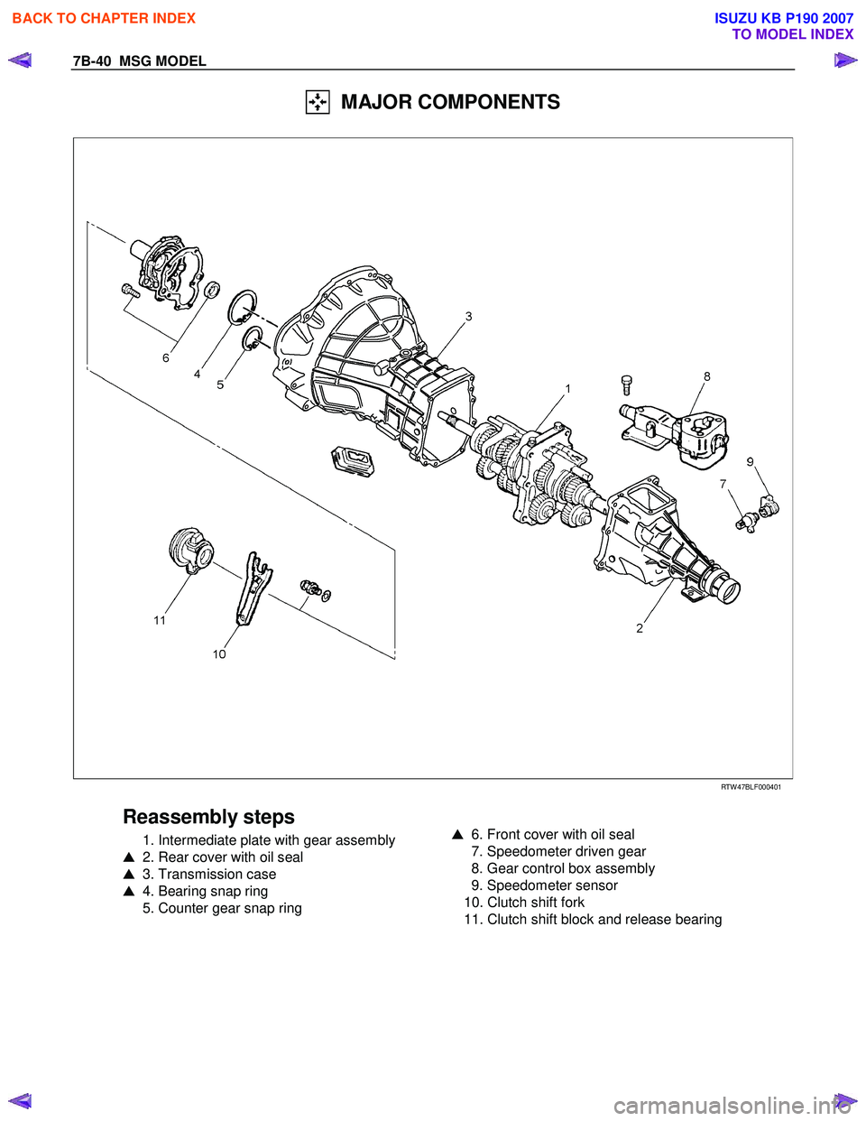
RTW 47BLF000401
Reassembly steps
1. Intermediate plate with gear assembly
� 2. Rear cover with oil seal
� 3. Transmission case
� 4. Bearing snap ring
5. Counter gear snap ring
� 6. Front cover with oil seal
7. Speedometer driven gear
8. Gear control box assembly
9. Speedometer sensor
10. Clutch shift fork
11. Clutch shift block and release bearing
BACK TO CHAPTER INDEX
TO MODEL INDEX
ISUZU KB P190 2007
Page 4615 of 6020
MANUAL TRANSMISSION 7B1-9
6. Remove the gear control lever.
7. Raise and support the vehicle with suitable stands.
8. Remove the rear propeller shaft.
NOTE: Apply alignment marks on the flange at the
differential side.
401RS023
9. Loosen the front exhaust pipe fixing nuts at the engine side but do not remove them. (Diesel engine
only)
RTW 67BSH000101
10. Disconnect the harness connectors and clips on the
transmission.
• Neutral Switch
• Back up Switch
• Car Speed Sensor
11. Remove the fuel pipe bracket with pipes from the transmission.
Diesel engine
220R300012
Legend
(1) Bolt
(2) Nut
(3) Fuel Pipe Assembly
C24SE
Scan-1
BACK TO CHAPTER INDEX
TO MODEL INDEX
ISUZU KB P190 2007
Page 4620 of 6020

NOTE: Tighten the lower bolt temporarily.
After installing the fuel pipe assembly, tighten the bolt to
the specified t")
7B1-14 MANUAL TRANSMISSION
5. Install the starter. (Diesel engine only)
NOTE: Tighten the lower bolt temporarily.
After installing the fuel pipe assembly, tighten the bolt to
the specified torque.
Torque: 76 N ⋅
⋅⋅
⋅
m (7.7 kgf ⋅
⋅⋅
⋅
m/56 lb ⋅
⋅⋅
⋅
ft)
6. Install the rear support rubber on the transmission and tighten the nuts to the specified torque.
Torque: 52 N ⋅
⋅⋅
⋅
m (5.3 kgf ⋅
⋅⋅
⋅
m/38 lb ⋅
⋅⋅
⋅
ft)
7. Install the middle part of the transmission crossmember and the bolts.
Tighten the nuts to the specified torque.
Torque: 67 N ⋅
⋅⋅
⋅
m (6.8 kgf ⋅
⋅⋅
⋅
m/49 lb ⋅
⋅⋅
⋅
ft)
8. Install the engine rear mount nuts fixing on the transmission crossmember.
Torque: 52 N ⋅
⋅⋅
⋅
m (5.3 kgf ⋅
⋅⋅
⋅
m/38 lb ⋅
⋅⋅
⋅
ft)
Remove the transmission jack from transmission
side.
9. Apply grease to the top hole portion of the shift fork. Install the slave cylinder and tighten the bolts to the
specified torque.
Torque: 76 N ⋅
⋅⋅
⋅
m (7.7 kgf ⋅
⋅⋅
⋅
m/56 lb ⋅
⋅⋅
⋅
ft)
10. Install the fuel pipe brackets on the transmission.
Install the fuel pipe assembly to the fuel brackets.
Torque: Bolt & Nut 76 N ⋅
⋅⋅
⋅
m (7.7 kgf ⋅
⋅⋅
⋅
m/56 lb ⋅
⋅⋅
⋅
ft)
Nut 37 N ⋅
⋅⋅
⋅
m (3.8 kgf ⋅
⋅⋅
⋅
m/27 lb ⋅
⋅⋅
⋅
ft)
Diesel engine
220R300012
Legend
(1) Bolt
(2) Nut
(3) Fuel Pipe Assembly
C24SE
Scan-1
11. Connect the transmission harness connectors and
clip. Connector: neutral switch, car speed sensor,
and backup switch.
12. Tighten the exhaust pipe fixing nuts to the specified torque. (Diesel engine only)
Torque: 67 N ⋅
⋅⋅
⋅
m (6.8 kgf ⋅
⋅⋅
⋅
m/49 lb ⋅
⋅⋅
⋅
ft)
RTW 67BSH000101
BACK TO CHAPTER INDEX
TO MODEL INDEX
ISUZU KB P190 2007
Page 4622 of 6020
7B1-16 MANUAL TRANSMISSION
Transmission Case
Major Component
RTW 77BLF003301
Legend
(1) Gear Control Box Assembly and Gasket (7) Shift Fork and Cover: Diesel engine
(2) Speedometer Sensor and Driven Gear (8) Counter Front Bearing Snap Ring
(3) Rear Cover Assembly (9) Front Cover (with Oil Seal)
(4) Intermediate Plate with Gear Assembly (10) Top Gear Bearing Snap Ring
(5) Transmission Case (11) Release Bearing: C24SE
(6) Release Bearing (with Spring) : Diesel engine (12) Shift Fork: C24SE
BACK TO CHAPTER INDEX
TO MODEL INDEX
ISUZU KB P190 2007

1. Apply setting")


 Gear Control Box Assembly and Gasket (7) Shift Fork and Cover: Diesel engine
(2) Spe")