Page 1632 of 6020
 6E-15
DLC and CAN (High output)
RTW76EXF005101
164 5 B-58 71
614
B-58
C-19�
Meter(+B)
10A EHCU C-67 (11)
SRS control unit B-31 (2)
Anti-theft control unit B-44 (2")
ENGINE CONTROL SYSTEM (4JK1/4JJ1) 6E-15
DLC and CAN (High output)
RTW76EXF005101
164 5 B-58 71
614
B-58
C-19�
Meter(+B)
10A EHCU C-67 (11)
SRS control unit B-31 (2)
Anti-theft control unit B-44 (2)
Fuse/
relay
box
(Cabin)
0.5�
RED/
YEL
ICU
IP cluster
DLCICU
H-18
C-2
0.5�
BLK
0.5�
BLK
0.5�
RED/
YEL
+B 2�
BLK
B-82�
Weld
splice 6 2BLK
13
3 B-56
ECM
Keyword 2000 0.5
BLK/
GRN
0.5
VIO/
GRN
0.3
BLK/
GRN
0.5�
BLU0.5�
YEL
Diagnostic
switch
Diagnostic switch CAN
high CAN
low
Ground Ground 2
H-18(RHD)
H-48(LHD)
7(RHD)
12(LHD) CAN
low
CAN
high
CANlow
CAN
high
67
66
177
C-58
C-94
56 0.5
BLU
0.5�
YEL
B-68
0.5�
BLU
4
3
2 4
3
2
C-135
J/C 1
C-136
J/C 20.5�
YEL
0.5BLU
0.5YEL
Except
Thailand
equipment TCM A/T
45 H-44 CAN
low
CAN
high
2
8
C-139
0.5�
BLU
4
3
2 4
3
2
C-150
J/C 5
C-151
J/C 6 0.5�
YEL
0.5�
BLU 0.5�
YEL 0.5BLU
0.5YEL DRM
(Euro 4
Specification)
CAN low
CAN
high
0.5�
BLU
3
1 2 3
1 2
B-103
J/C 3
B-104
J/C 4 0.5�
YEL
0.5�
BLU 0.5�
YEL
22
11
H-6 M/T
Thailand
equipment
11
12
H-18
A/T
Thailand
equipment
21
1
H-7
BACK TO CHAPTER INDEX
TO MODEL INDEX
ISUZU KB P190 2007
Page 1633 of 6020

Gauges
RTW76EXF004701
Fuel
consumption
signal
output
11 676
8
7 5 B-56
C-107 8 B-24
17
0.3�
BLK/
YEL
0.5�
YEL
0.5�
YEL
0.5�
YEL
0.5�
BLK
0.85�
BLK 6
7 0.")
6E-16 ENGINE CONTROL SYSTEM (4JK1/4JJ1)
Gauges
RTW76EXF004701
Fuel
consumption
signal
output
11 676
8
7 5 B-56
C-107 8 B-24
17
0.3�
BLK/
YEL
0.5�
YEL
0.5�
YEL
0.5�
YEL
0.5�
BLK
0.85�
BLK 6
7 0.5
BLK/
YEL 0.5
BLK/
YEL
0.5�
BLK/
YEL 0.5
BLK/
YEL 0.5
BLK/
YEL
0.5
BLK/
YEL 0.5�
BLK
0.85�
BLK
0.85�
BLK
0.85�
BLK
0.85�
BLK 0.5�
BLK
0.5�
BLK0.5�
WHT
0.5�
BLK/
RED
0.3�
BLK/
RED
20
13
23 0.3�
YEL/
RED
0.3�
YEL/
RED 0.5
YEL/
BLK
0.5�
YEL/
BLK
0.5�
YEL/
RED 0.5�
YEL/
BLK
0.5�
GRN/
RED
ECM(27)
ECM(26) 0.3�
BLK/
RED
0.5�
BLK/
RED
4
20.3�
ORN/
WHT
0.5�
ORN/
WHT
Fuel
tank
sender
unit
10 C-94
TCM
Engine
speed
signal
inputTCM
7 C-94
62 C-58 A/T
Engine
speed
signal
output
33 IP
cluster
70 B-23
B-24
B-23
H-18
H-4
12
5
H-9
F-2
F-2
3
22 E-41
31
H-4
2 H-6
H-4 M/T
A/T 4WD
A/T 2WD
10
H-15
E-10
E-10 4
C-58
ECT
sensor
VSS
E-44
E-44
1
2 3
C-14�
Meter
10A
Fuse/
relay
box
(Cabin) Speedometer
Fuel gaugeEngine coolant
temperature gauge
Tachometer Multi display
ECM
Signal
ECM
+B VSS
signal
output
BACK TO CHAPTER INDEX
TO MODEL INDEX
ISUZU KB P190 2007
Page 1638 of 6020
ENGINE CONTROL SYSTEM (4JK1/4JJ1) 6E-21
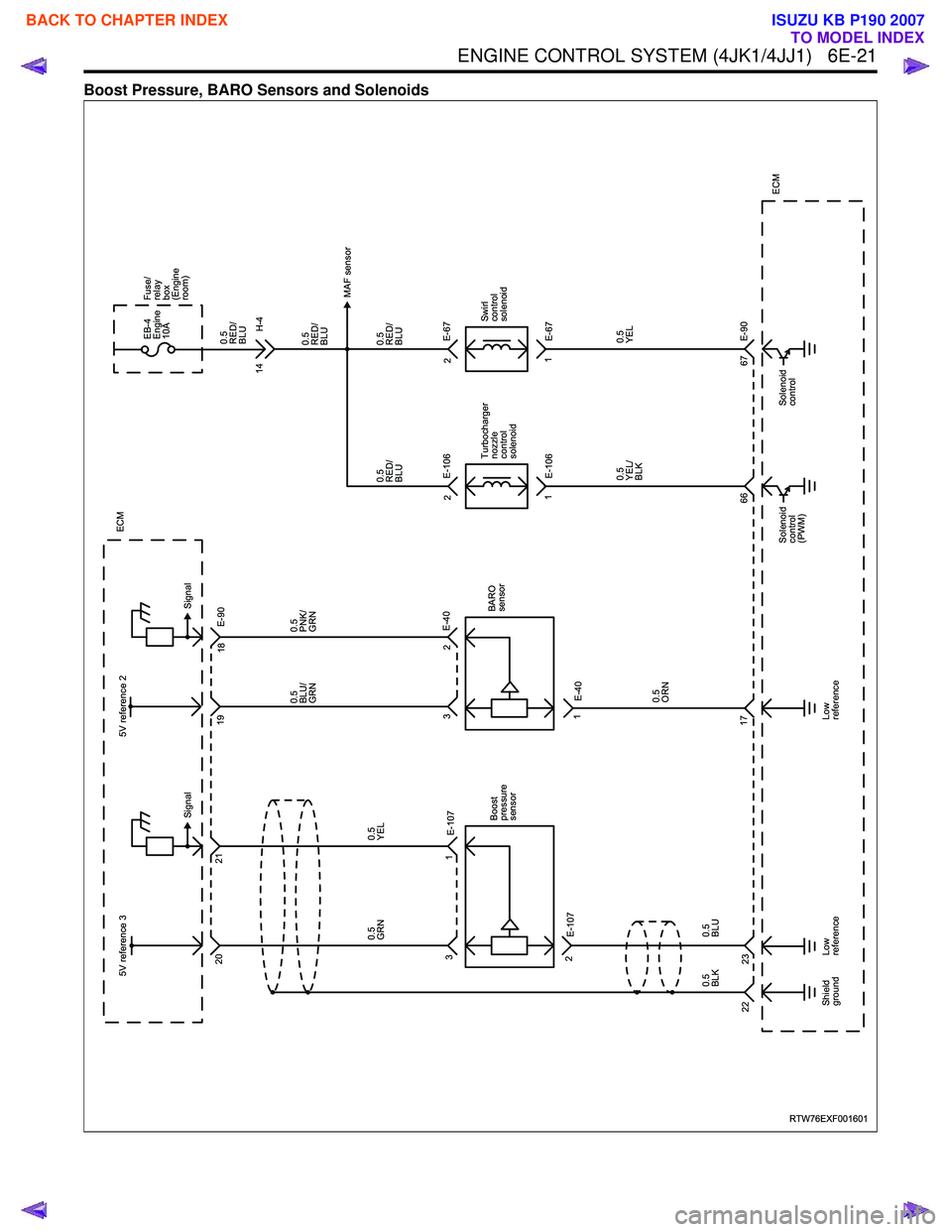
Boost Pressure, BARO Sensors and Solenoids
RTW76EXF001601
0.5�
BLK23
22 5V reference 3
20
31 E-107
0.5
YEL
0.5
GRN
2 E-107
0.5�
BLU Boost
pressure
sensor
21
Low
reference
Shield
ground Signal
MAF sensor
ECM
ECM
Signal
E-90
0.5�
BLU/
GRN
3 E-40
17 1
E-40
0.5�
ORN BARO
sensor
5V reference 2
Low
reference
19
2
18
0.5�
PNK/
GRN
E-106
E-106 Turbocharger
nozzle
control
solenoid
0.5�
RED/
BLU
0.5�
YEL/
BLK
66
Solenoid
control
(PWM) 2
1 E-67
E-90
E-67
Swirl
control
solenoid
0.5�
RED/
BLU
0.5�
RED/
BLU
0.5�
YEL
67
Solenoid
control 2
1
14
0.5�
RED/
BLU
H-4
EB-4
Engine
10A
Fuse/
relay
box
(Engine
room)
BACK TO CHAPTER INDEX
TO MODEL INDEX
ISUZU KB P190 2007
Page 1639 of 6020
6E-22 ENGINE CONTROL SYSTEM (4JK1/4JJ1)
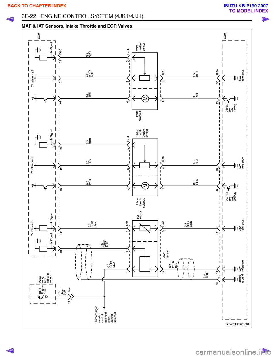
MAF & IAT Sensors, Intake Throttle and EGR Valves
RTW76EXF001501
Intake
throttle
position
sensor
Intake
throttle
solenoid 6
35 3
0.5�
WHT
0.5�
ORN
0.5�
GRY
0.5�
BLU E-38
56 1
0.5�
RED E-71
E-90
63 6
0.5�
YEL
36
57
55
5
2 5V reference 3
5V reference
ECM
ECM
Control
low
side
(PWM) Control
low
side
(PWM) 30
5V reference 2
0.5�
WHT/
BLU
31
0.5�
GRY
0.5�
RED
0.5
BRN
EGR
solenoid EGR
position
sensor
32
62 E-90
43 1
2
Low
reference Low
reference
Low
reference
Low
reference
Shield
ground 41
0.5
BLU/
RED
0.5�
BLU/
GRN
0.5�
BLK 0.5
WHT/
BLU MAF
sensor Signal
Signal
Signal
Signal
40
0.5�
RED/
BLU 0.5�
ORN/
BLU
4
3
1 E-47
5
61
43
42 2
E-47IAT
sensor
14
0.5�
RED/
BLU
H-4
EB-4
Engine
10A Fuse/
relay
box
(Engine
room)
E-38E-71
Turbocharger
nozzle
control
solenoid
Swirl
control
solenoid +B
+B
BACK TO CHAPTER INDEX
TO MODEL INDEX
ISUZU KB P190 2007
Page 1641 of 6020
6E-24 ENGINE CONTROL SYSTEM (4JK1/4JJ1)
A/C Control System and Glow Control System
RTW76EXF001701
9 C-107C-58
X-14
X-14 A/C
compressor
relay
13
5 2 X-5
X-5
H-4 Glow
relay
42
1
3
ECM
Ignition
signal
Thermo
relay
signal X-15
X-15 Thermo
relay
Refrigerant
pressure
switch 0.5�
GRN/
YEL 0.5�
GRN/
BLK 0.5�
GRN/
ORN
0.5�
GRN/
BLK 0.5�
GRN/
ORN
3�
BLK/
RED
Glow
plug
Compressor
clutch
Relay
control Relay
control
H-4
E-3�
( )=A/T 0.5�
BRN
0.5�
GRN/
RED 0.5�
BLK/
BLU
0.5�
WHT/
GRN 3
RED/
WHT
3�
BLK/
RED
0.5�
GRN/
BLK
0.5�
BRN
0.5�
BRNEB-13�
A/C�
10A Fuse/
relay
box
(Engine room)
0.5�
BRN
23 1
5
1 SBF8�
Glow
60A Fuse/
relay
box
(Cabin)
C-6�
Engine
10A
0.5�
WHT/
GRN
0.5�
WHT/
GRN
Starter
cut
relay Refer to
Power distribution
15 19
(28)
E-49
72
37
55
4
BACK TO CHAPTER INDEX
TO MODEL INDEX
ISUZU KB P190 2007
Page 1642 of 6020
ENGINE CONTROL SYSTEM (4JK1/4JJ1) 6E-25
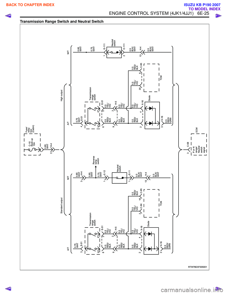
Transmission Range Switch and Neutral Switch
RTW76EXF005001
E-51
H-5
E-51
Transmission
range
switch
3
2
8 NP
X-16
X-16 C-94 C-95
TCM
Diode
4
2
3 0.75�
WHT
0.5�
RED/
BLK
0.5�
RED/
BLK
0.5�
RED/
BLK 0.5�
YEL/
VIO
0.5�
YEL/
VIO
0.5�
YEL/
VIO 0.5�
YEL/
VIO 0.5�
RED/
BLK
0.5�
RED/
GRN
9
2
10
2 Neutral
switch
M/T
Standard output
A/T
0.5�
BLK/
WHT Reverse
lamp
switch
0.5�
BLK/
WHT
0.85�
WHT
0.85�
WHT
0.75�
WHT
1 E-11
13 H-4 1 E-12 0.85�
WHT
3 H-4
3 H-4 E-51
H-5
E-51
Transmission
range
switch
4
5
6 NP
X-16
X-16 C-95
TCM
Diode
4
2
3 0.75�
WHT
0.5�
RED/
BLK
0.5�
RED/
BLK
0.5�
RED/
BLK 0.5�
YEL/
VIO
0.5�
YEL/
VIO
0.5�
YEL/
VIO 0.5�
YEL/
VIO 0.5�
RED/
BLK
0.5�
RED/
GRN
9
2
8
20 Neutral
switch
M/T
High output
A/T
0.5�
BLK/
WHT
0.5�
BLK/
WHT
0.85�
WHT
0.75�
WHT
2 E-111
13 H-4 1 E-111
C-10
Back up
15A
Fuse/
relay
box
(Cabin)
3 C-58 ECM
PorN
range/
Neutral
switch
signal
BACK TO CHAPTER INDEX
TO MODEL INDEX
ISUZU KB P190 2007
Page 1643 of 6020
6E-26 ENGINE CONTROL SYSTEM (4JK1/4JJ1)
Brake Switch and Cruise Control
RTW76EXF004001
Brake
switch
C-44
4
C-44
3 Cruise
main
switch
Fuse /
relay
box
(Cabin)
4
3
3
1
4
2 0.5
GRY/
GRN
0.5
WHT/
GRN
0.5
GRN/
WHT
0.5
WHT/
GRN 6
12 0.3
GRN/
RED
0.3
RED/
GRN B-67
2
B-67
1
10
13
0.5
GRN/
WHT
H-18
50
0.5
WHT/
GRN
0.5
GRN 6
14
1
21 0.5
BRN/
YEL
9
29 Combination
switch
Set /
coast
switch
Resume /
accel.
switch
Cancel
switch
ECM
0.5
LT GRN
Set /
coast
switch
signal
Resume /
accel.
switch
signal
Cancel
switch
signal
IP cluster
Weld
splice2
Weld
splice 1
Cruise
main
switch
signal
Brake
switch 2
(Cruise release)
Brake
switch 1
(Stop lamp) B-59
C-58
12
30
0.5
WHT/
GRN
B-59
11
0.5
WHT/
GRN
0.5
WHT/
GRN
0.5
WHT/
GRN
0.5
RED
0.85
RED 0.85
GRN
H-7
C-107
9 C-6
Engine
10A
C-15
STOP
15A
Lamp
control
Except
Euro 4
Specification
Euro 4
Specification
BACK TO CHAPTER INDEX
TO MODEL INDEX
ISUZU KB P190 2007
Page 1673 of 6020

Scan Tool Does Not Power Up
Circuit Description
The data link connector (DLC) is a standardized 16-
cavity connector. Connector design and location is
dict")
6E-56 ENGINE CONTROL SYSTEM (4JK1/4JJ1)
Scan Tool Does Not Power Up
Circuit Description
The data link connector (DLC) is a standardized 16-
cavity connector. Connector design and location is
dictated by an industry wide standard, and is required
to provide the following:
• Scan tool power battery positive voltage at terminal 16.
• Scan tool power ground at terminal 4. • Common signal ground at terminal 5.
The scan tool will power up with the ignition OFF.
Some modules however, will not communicate unless
the ignition is ON.
Schematic Reference: Engine Controls Schematics
Connector End View Reference: Engine Controls
Connector End Views or ECM Connector End Views
Circuit/ System Testing Scan Tool Does Not Power Up
Step Action Value(s)Yes No
1 Important
: Make sure the scan tool works properly
on another vehicle before using this chart.
1. Turn OFF the ignition.
2. Inspect the Meter (+B) (10A) fuse in the cabin fuse block.
Is the Meter (+B) (10A) fuse open? —
Go to Step 2 Go to Step 3
2 Replace the Meter (+B) (10A) fuse. If the fuse
continues to open, repair the short to ground on
one of the circuits that is fed by the Meter (+B)
(10A) fuse or replace the shorted attached
component.
Did you complete the repair? —
Go to Step 7
—
31. Check each circuit at the data link connector
(DLC) (B-58) for a backed out, spread or
missing terminal.
2. Repair the terminal as necessary.
Did you find and complete the repair? —
Go to Step 7 Go to Step 4
4 Connect a test lamp between the +B circuit (pin 16
of B-58) at the DLC and a known good ground.
Does the test lamp illuminate? —
Go to Step 6 Go to Step 5
5 Repair the open in the battery voltage circuit to the
DLC.
Did you complete the repair? —
Go to Step 7
—
61. Test each ground circuit at the DLC (pins 4
and 5 of B-58) for an open circuit or high
resistance.
2. Repair the circuit(s), clean or tighten ground as necessary.
Did you find and correct the condition? —
Go to Step 7 Go to Intermittent
Conditions
7 1. Connect the scan tool to the DLC.
2. Attempt to turn ON the scan tool.
Does the scan tool ON? —
System OK Go to Step 1
BACK TO CHAPTER INDEX
TO MODEL INDEX
ISUZU KB P190 2007

A/C Control System and Glow Control System
RTW76EXF001701
9 C-107C-58
X-14
X-14 A/C
compressor
relay
13
5 2 X-5
X-5
H-4 Glow
relay
42
1
3
ECM
Ignition
sig")

Brake Switch and Cruise Control
RTW76EXF004001
Brake
switch
C-44
4
C-44
3 Cruise
main
switch
Fuse /
relay
box
(Cabin)
4
3
3
1
4
2 0.5
GRY/
GRN
0.5
WHT/")