2007 ISUZU KB P190 fuse
[x] Cancel search: fusePage 1720 of 6020
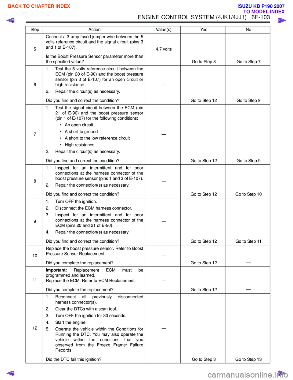
ENGINE CONTROL SYSTEM (4JK1/4JJ1) 6E-103
5Connect a 3-amp fused jumper wire between the 5
volts reference circuit and the signal circuit (pins 3
and 1 of E-107).
Is the Boost Pressure Sensor parameter more than
the specified value? 4.7 volts
Go to Step 8 Go to Step 7
6 1. Test the 5 volts reference circuit between the
ECM (pin 20 of E-90) and the boost pressure
sensor (pin 3 of E-107) for an open circuit or
high resistance.
2. Repair the circuit(s) as necessary.
Did you find and correct the condition? —
Go to Step 12 Go to Step 9
7 1. Test the signal circuit between the ECM (pin
21 of E-90) and the boost pressure sensor
(pin 1 of E-107) for the following conditions:
• An open circuit
• A short to ground
• A short to the low reference circuit
• High resistance
2. Repair the circuit(s) as necessary.
Did you find and correct the condition? —
Go to Step 12 Go to Step 9
8 1. Inspect for an intermittent and for poor
connections at the harness connector of the
boost pressure sensor (pins 1 and 3 of E-107).
2. Repair the connection(s) as necessary.
Did you find and correct the condition? —
Go to Step 12 Go to Step 10
9 1. Turn OFF the ignition.
2. Disconnect the ECM harness connector.
3. Inspect for an intermittent and for poor connections at the harness connector of the
ECM (pins 20 and 21 of E-90).
4. Repair the connection(s) as necessary.
Did you find and correct the condition? —
Go to Step 12 Go to Step 11
10 Replace the boost pressure sensor. Refer to Boost
Pressure Sensor Replacement.
Did you complete the replacement? —
Go to Step 12
—
11Important:
Replacement ECM must be
programmed and learned.
Replace the ECM. Refer to ECM Replacement.
Did you complete the replacement? —
Go to Step 12
—
121. Reconnect all previously disconnected
harness connector(s).
2. Clear the DTCs with a scan tool.
3. Turn OFF the ignition for 30 seconds.
4. Start the engine.
5. Operate the vehicle within the Conditions for Running the DTC. You may also operate the
vehicle within the conditions that you
observed from the Freeze Frame/ Failure
Records.
Did the DTC fail this ignition? —
Go to Step 3 Go to Step 13
Step
Action Value(s)Yes No
BACK TO CHAPTER INDEX
TO MODEL INDEX
ISUZU KB P190 2007
Page 1725 of 6020
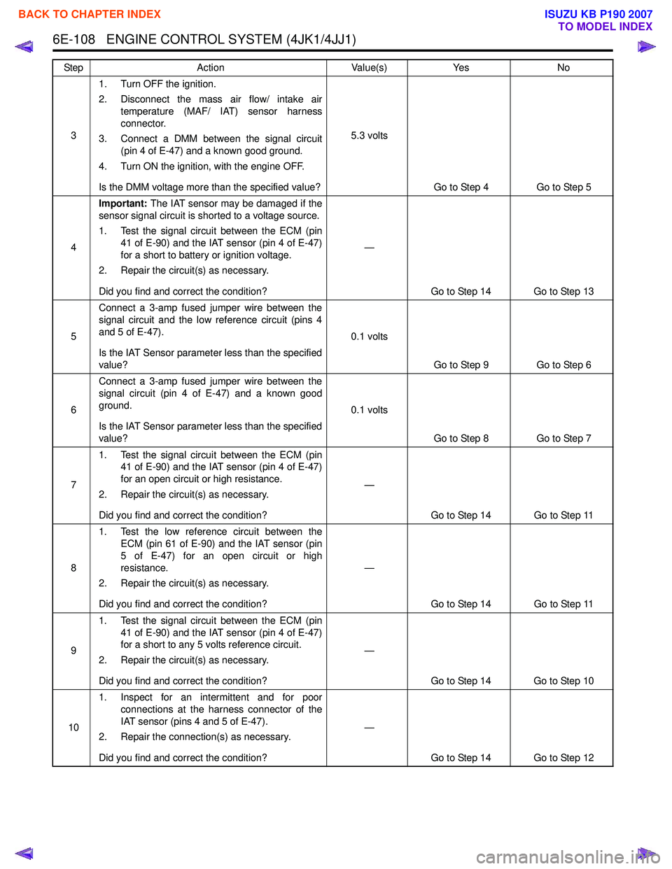
6E-108 ENGINE CONTROL SYSTEM (4JK1/4JJ1)
31. Turn OFF the ignition.
2. Disconnect the mass air flow/ intake air temperature (MAF/ IAT) sensor harness
connector.
3. Connect a DMM between the signal circuit (pin 4 of E-47) and a known good ground.
4. Turn ON the ignition, with the engine OFF.
Is the DMM voltage more than the specified value? 5.3 volts
Go to Step 4 Go to Step 5
4 Important:
The IAT sensor may be damaged if the
sensor signal circuit is shorted to a voltage source.
1. Test the signal circuit between the ECM (pin 41 of E-90) and the IAT sensor (pin 4 of E-47)
for a short to battery or ignition voltage.
2. Repair the circuit(s) as necessary.
Did you find and correct the condition? —
Go to Step 14 Go to Step 13
5 Connect a 3-amp fused jumper wire between the
signal circuit and the low reference circuit (pins 4
and 5 of E-47).
Is the IAT Sensor parameter less than the specified
value? 0.1 volts
Go to Step 9 Go to Step 6
6 Connect a 3-amp fused jumper wire between the
signal circuit (pin 4 of E-47) and a known good
ground.
Is the IAT Sensor parameter less than the specified
value? 0.1 volts
Go to Step 8 Go to Step 7
7 1. Test the signal circuit between the ECM (pin
41 of E-90) and the IAT sensor (pin 4 of E-47)
for an open circuit or high resistance.
2. Repair the circuit(s) as necessary.
Did you find and correct the condition? —
Go to Step 14 Go to Step 11
8 1. Test the low reference circuit between the
ECM (pin 61 of E-90) and the IAT sensor (pin
5 of E-47) for an open circuit or high
resistance.
2. Repair the circuit(s) as necessary.
Did you find and correct the condition? —
Go to Step 14 Go to Step 11
9 1. Test the signal circuit between the ECM (pin
41 of E-90) and the IAT sensor (pin 4 of E-47)
for a short to any 5 volts reference circuit.
2. Repair the circuit(s) as necessary.
Did you find and correct the condition? —
Go to Step 14 Go to Step 10
10 1. Inspect for an intermittent and for poor
connections at the harness connector of the
IAT sensor (pins 4 and 5 of E-47).
2. Repair the connection(s) as necessary.
Did you find and correct the condition? —
Go to Step 14 Go to Step 12
Step
Action Value(s)Yes No
BACK TO CHAPTER INDEX
TO MODEL INDEX
ISUZU KB P190 2007
Page 1731 of 6020
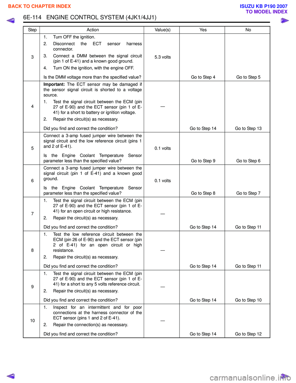
6E-114 ENGINE CONTROL SYSTEM (4JK1/4JJ1)
31. Turn OFF the ignition.
2. Disconnect the ECT sensor harness connector.
3. Connect a DMM between the signal circuit (pin 1 of E-41) and a known good ground.
4. Turn ON the ignition, with the engine OFF.
Is the DMM voltage more than the specified value? 5.3 volts
Go to Step 4 Go to Step 5
4 Important:
The ECT sensor may be damaged if
the sensor signal circuit is shorted to a voltage
source.
1. Test the signal circuit between the ECM (pin 27 of E-90) and the ECT sensor (pin 1 of E-
41) for a short to battery or ignition voltage.
2. Repair the circuit(s) as necessary.
Did you find and correct the condition? —
Go to Step 14 Go to Step 13
5 Connect a 3-amp fused jumper wire between the
signal circuit and the low reference circuit (pins 1
and 2 of E-41).
Is the Engine Coolant Temperature Sensor
parameter less than the specified value? 0.1 volts
Go to Step 9 Go to Step 6
6 Connect a 3-amp fused jumper wire between the
signal circuit (pin 1 of E-41) and a known good
ground.
Is the Engine Coolant Temperature Sensor
parameter less than the specified value? 0.1 volts
Go to Step 8 Go to Step 7
7 1. Test the signal circuit between the ECM (pin
27 of E-90) and the ECT sensor (pin 1 of E-
41) for an open circuit or high resistance.
2. Repair the circuit(s) as necessary.
Did you find and correct the condition? —
Go to Step 14 Go to Step 11
8 1. Test the low reference circuit between the
ECM (pin 26 of E-90) and the ECT sensor (pin
2 of E-41) for an open circuit or high
resistance.
2. Repair the circuit(s) as necessary.
Did you find and correct the condition? —
Go to Step 14 Go to Step 11
9 1. Test the signal circuit between the ECM (pin
27 of E-90) and the ECT sensor (pin 1 of E-
41) for a short to any 5 volts reference circuit.
2. Repair the circuit(s) as necessary.
Did you find and correct the condition? —
Go to Step 14 Go to Step 10
10 1. Inspect for an intermittent and for poor
connections at the harness connector of the
ECT sensor (pins 1 and 2 of E-41).
2. Repair the connection(s) as necessary.
Did you find and correct the condition? —
Go to Step 14 Go to Step 12
Step
Action Value(s)Yes No
BACK TO CHAPTER INDEX
TO MODEL INDEX
ISUZU KB P190 2007
Page 1734 of 6020
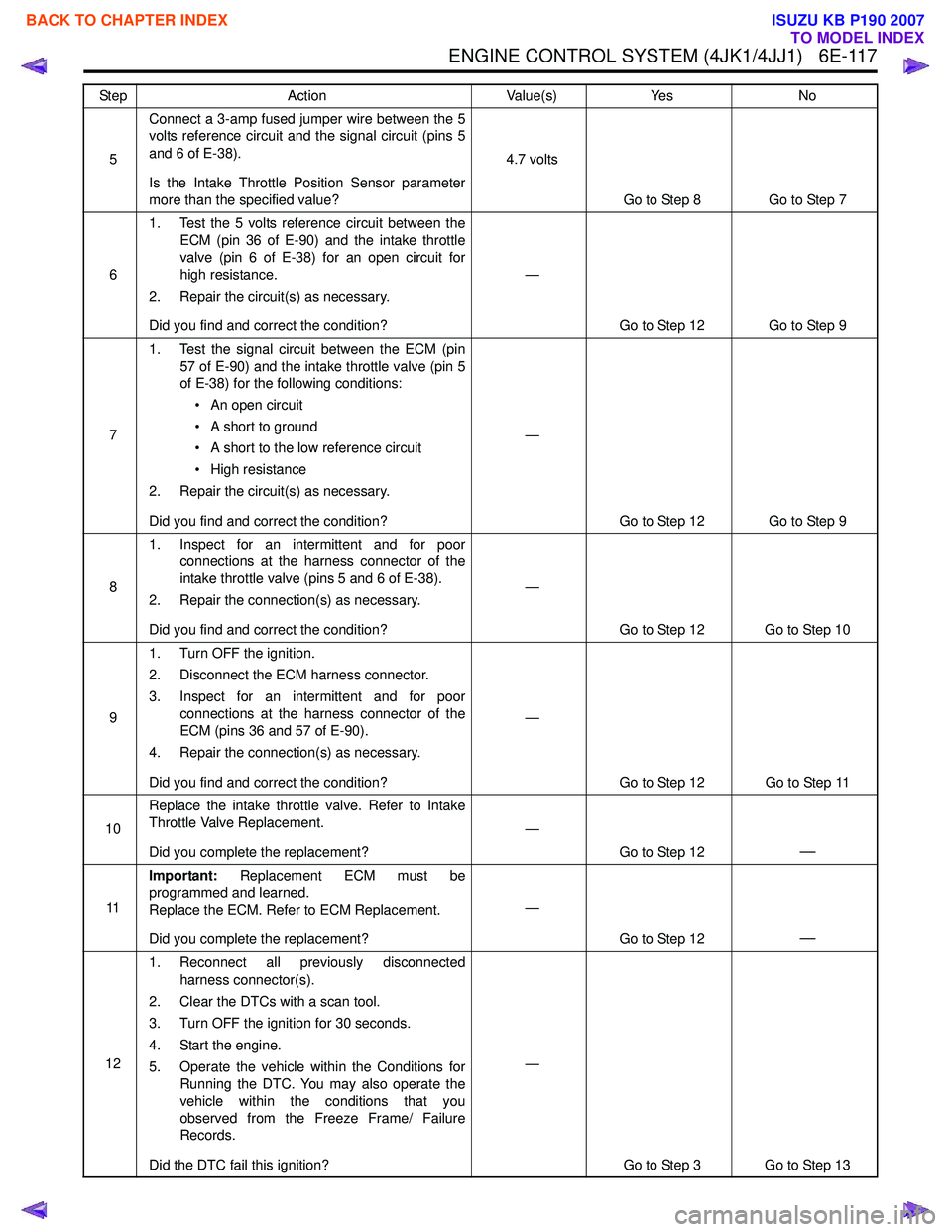
ENGINE CONTROL SYSTEM (4JK1/4JJ1) 6E-117
5Connect a 3-amp fused jumper wire between the 5
volts reference circuit and the signal circuit (pins 5
and 6 of E-38).
Is the Intake Throttle Position Sensor parameter
more than the specified value? 4.7 volts
Go to Step 8 Go to Step 7
6 1. Test the 5 volts reference circuit between the
ECM (pin 36 of E-90) and the intake throttle
valve (pin 6 of E-38) for an open circuit for
high resistance.
2. Repair the circuit(s) as necessary.
Did you find and correct the condition? —
Go to Step 12 Go to Step 9
7 1. Test the signal circuit between the ECM (pin
57 of E-90) and the intake throttle valve (pin 5
of E-38) for the following conditions:
• An open circuit
• A short to ground
• A short to the low reference circuit
• High resistance
2. Repair the circuit(s) as necessary.
Did you find and correct the condition? —
Go to Step 12 Go to Step 9
8 1. Inspect for an intermittent and for poor
connections at the harness connector of the
intake throttle valve (pins 5 and 6 of E-38).
2. Repair the connection(s) as necessary.
Did you find and correct the condition? —
Go to Step 12 Go to Step 10
9 1. Turn OFF the ignition.
2. Disconnect the ECM harness connector.
3. Inspect for an intermittent and for poor connections at the harness connector of the
ECM (pins 36 and 57 of E-90).
4. Repair the connection(s) as necessary.
Did you find and correct the condition? —
Go to Step 12 Go to Step 11
10 Replace the intake throttle valve. Refer to Intake
Throttle Valve Replacement.
Did you complete the replacement? —
Go to Step 12
—
11Important:
Replacement ECM must be
programmed and learned.
Replace the ECM. Refer to ECM Replacement.
Did you complete the replacement? —
Go to Step 12
—
121. Reconnect all previously disconnected
harness connector(s).
2. Clear the DTCs with a scan tool.
3. Turn OFF the ignition for 30 seconds.
4. Start the engine.
5. Operate the vehicle within the Conditions for Running the DTC. You may also operate the
vehicle within the conditions that you
observed from the Freeze Frame/ Failure
Records.
Did the DTC fail this ignition? —
Go to Step 3 Go to Step 13
Step
Action Value(s)Yes No
BACK TO CHAPTER INDEX
TO MODEL INDEX
ISUZU KB P190 2007
Page 1739 of 6020
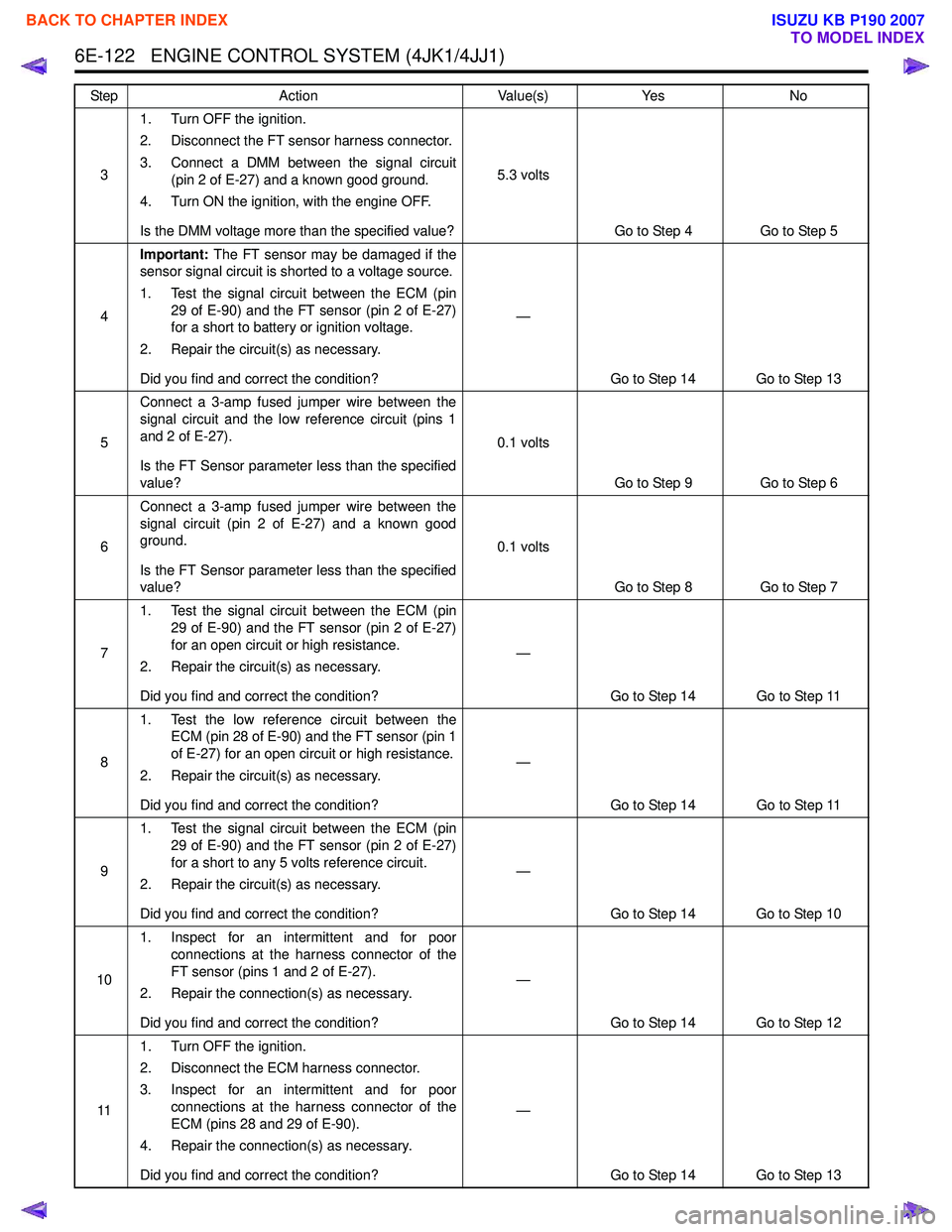
6E-122 ENGINE CONTROL SYSTEM (4JK1/4JJ1)
31. Turn OFF the ignition.
2. Disconnect the FT sensor harness connector.
3. Connect a DMM between the signal circuit (pin 2 of E-27) and a known good ground.
4. Turn ON the ignition, with the engine OFF.
Is the DMM voltage more than the specified value? 5.3 volts
Go to Step 4 Go to Step 5
4 Important:
The FT sensor may be damaged if the
sensor signal circuit is shorted to a voltage source.
1. Test the signal circuit between the ECM (pin 29 of E-90) and the FT sensor (pin 2 of E-27)
for a short to battery or ignition voltage.
2. Repair the circuit(s) as necessary.
Did you find and correct the condition? —
Go to Step 14 Go to Step 13
5 Connect a 3-amp fused jumper wire between the
signal circuit and the low reference circuit (pins 1
and 2 of E-27).
Is the FT Sensor parameter less than the specified
value? 0.1 volts
Go to Step 9 Go to Step 6
6 Connect a 3-amp fused jumper wire between the
signal circuit (pin 2 of E-27) and a known good
ground.
Is the FT Sensor parameter less than the specified
value? 0.1 volts
Go to Step 8 Go to Step 7
7 1. Test the signal circuit between the ECM (pin
29 of E-90) and the FT sensor (pin 2 of E-27)
for an open circuit or high resistance.
2. Repair the circuit(s) as necessary.
Did you find and correct the condition? —
Go to Step 14 Go to Step 11
8 1. Test the low reference circuit between the
ECM (pin 28 of E-90) and the FT sensor (pin 1
of E-27) for an open circuit or high resistance.
2. Repair the circuit(s) as necessary.
Did you find and correct the condition? —
Go to Step 14 Go to Step 11
9 1. Test the signal circuit between the ECM (pin
29 of E-90) and the FT sensor (pin 2 of E-27)
for a short to any 5 volts reference circuit.
2. Repair the circuit(s) as necessary.
Did you find and correct the condition? —
Go to Step 14 Go to Step 10
10 1. Inspect for an intermittent and for poor
connections at the harness connector of the
FT sensor (pins 1 and 2 of E-27).
2. Repair the connection(s) as necessary.
Did you find and correct the condition? —
Go to Step 14 Go to Step 12
11 1. Turn OFF the ignition.
2. Disconnect the ECM harness connector.
3. Inspect for an intermittent and for poor connections at the harness connector of the
ECM (pins 28 and 29 of E-90).
4. Repair the connection(s) as necessary.
Did you find and correct the condition? —
Go to Step 14 Go to Step 13
Step
Action Value(s)Yes No
BACK TO CHAPTER INDEX
TO MODEL INDEX
ISUZU KB P190 2007
Page 1743 of 6020
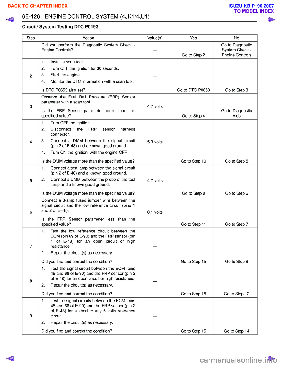
6E-126 ENGINE CONTROL SYSTEM (4JK1/4JJ1)
Circuit/ System Testing DTC P0193
StepAction Value(s)Yes No
1 Did you perform the Diagnostic System Check -
Engine Controls? —
Go to Step 2 Go to Diagnostic
System Check -
Engine Controls
2 1. Install a scan tool.
2. Turn OFF the ignition for 30 seconds.
3. Start the engine.
4. Monitor the DTC Information with a scan tool.
Is DTC P0653 also set? —
Go to DTC P0653 Go to Step 3
3 Observe the Fuel Rail Pressure (FRP) Sensor
parameter with a scan tool.
Is the FRP Sensor parameter more than the
specified value? 4.7 volts
Go to Step 4 Go to Diagnostic
Aids
4 1. Turn OFF the ignition.
2. Disconnect the FRP sensor harness connector.
3. Connect a DMM between the signal circuit (pin 2 of E-48) and a known good ground.
4. Turn ON the ignition, with the engine OFF.
Is the DMM voltage more than the specified value? 5.3 volts
Go to Step 10 Go to Step 5
5 1. Connect a test lamp between the signal circuit
(pin 2 of E-48) and a known good ground.
2. Connect a DMM between the probe of the test lamp and a known good ground.
Is the DMM voltage more than the specified value? 4.7 volts
Go to Step 9 Go to Step 6
6 Connect a 3-amp fused jumper wire between the
signal circuit and the low reference circuit (pins 1
and 2 of E-48).
Is the FRP Sensor parameter less than the
specified value? 0.1 volts
Go to Step 11 Go to Step 7
7 1. Test the low reference circuit between the
ECM (pin 69 of E-90) and the FRP sensor (pin
1 of E-48) for an open circuit or high
resistance.
2. Repair the circuit(s) as necessary.
Did you find and correct the condition? —
Go to Step 15 Go to Step 8
8 1. Test the signal circuit between the ECM (pins
48 and 68 of E-90) and the FRP sensor (pin 2
of E-48) for an open circuit or high resistance.
2. Repair the circuit(s) as necessary.
Did you find and correct the condition? —
Go to Step 15 Go to Step 12
9 1. Test the signal circuits between the ECM (pins
48 and 68 of E-90) and the FRP sensor (pin 2
of E-48) for a short to any 5 volts reference
circuit.
2. Repair the circuit(s) as necessary.
Did you find and correct the condition? —
Go to Step 15 Go to Step 14
BACK TO CHAPTER INDEX
TO MODEL INDEX
ISUZU KB P190 2007
Page 1757 of 6020
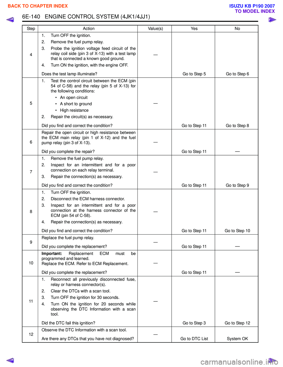
6E-140 ENGINE CONTROL SYSTEM (4JK1/4JJ1)
41. Turn OFF the ignition.
2. Remove the fuel pump relay.
3. Probe the ignition voltage feed circuit of the relay coil side (pin 3 of X-13) with a test lamp
that is connected a known good ground.
4. Turn ON the ignition, with the engine OFF.
Does the test lamp illuminate? —
Go to Step 5 Go to Step 6
5 1. Test the control circuit between the ECM (pin
54 of C-58) and the relay (pin 5 of X-13) for
the following conditions:
• An open circuit
• A short to ground
• High resistance
2. Repair the circuit(s) as necessary.
Did you find and correct the condition? —
Go to Step 11 Go to Step 8
6 Repair the open circuit or high resistance between
the ECM main relay (pin 1 of X-12) and the fuel
pump relay (pin 3 of X-13).
Did you complete the repair? —
Go to Step 11
—
71. Remove the fuel pump relay.
2. Inspect for an intermittent and for a poor connection on each relay terminal.
3. Repair the connection(s) as necessary.
Did you find and correct the condition? —
Go to Step 11 Go to Step 9
8 1. Turn OFF the ignition.
2. Disconnect the ECM harness connector.
3. Inspect for an intermittent and for a poor connection at the harness connector of the
ECM (pin 54 of C-58).
4. Repair the connection(s) as necessary.
Did you find and correct the condition? —
Go to Step 11 Go to Step 10
9 Replace the fuel pump relay.
Did you complete the replacement? —
Go to Step 11
—
10Important:
Replacement ECM must be
programmed and learned.
Replace the ECM. Refer to ECM Replacement.
Did you complete the replacement? —
Go to Step 11
—
111. Reconnect all previously disconnected fuse,
relay or harness connector(s).
2. Clear the DTCs with a scan tool.
3. Turn OFF the ignition for 30 seconds.
4. Turn ON the ignition for 20 seconds while observing the DTC Information with a scan
tool.
Did the DTC fail this ignition? —
Go to Step 3 Go to Step 12
12 Observe the DTC Information with a scan tool.
Are there any DTCs that you have not diagnosed? —
Go to DTC List System OK
Step
Action Value(s)Yes No
BACK TO CHAPTER INDEX
TO MODEL INDEX
ISUZU KB P190 2007
Page 1776 of 6020

ENGINE CONTROL SYSTEM (4JK1/4JJ1) 6E-159
41. Turn OFF the ignition.
2. Replace the glow relay with the starter relay or replace with a known good relay.
3. Perform the Glow Relay Control with a scan tool.
4. Command the relay ON and OFF.
Does the glow relay click with each command? —
Go to Step 8 Go to Step 5
5 1. Turn OFF the ignition.
2. Remove the glow relay.
3. Turn ON the ignition, with the engine OFF.
4. Probe the ignition voltage feed circuit of the relay coil side (pin 2 of X-5) with a test lamp
that is connected to a known good ground.
Does the test lamp illuminate? —
Go to Step 6 Go to Step 7
6 1. Test the control circuit between the ECM (pin
37 of C-58) and the relay (pin 3 of X-5) for the
following conditions:
• An open circuit
• A short to ground
• A short to battery or ignition voltage
2. Repair the circuit(s) as necessary.
Did you find and correct the condition? —
Go to Step 12 Go to Step 9
7 Repair the open circuit or high resistance between
the Engine (10A) fuse and the glow relay coil side
(pin 2 of X-5). Check the Engine (10A) fuse first.
Did you complete the repair? —
Go to Step 12
—
81. Remove the glow relay.
2. Inspect for an intermittent and for a poor connection on each relay terminal.
3. Repair the connection(s) as necessary.
Did you find and correct the condition? —
Go to Step 12 Go to Step 10
9 1. Turn OFF the ignition.
2. Disconnect the ECM harness connector.
3. Inspect for an intermittent and for a poor connection at the harness connector of the
ECM (pin 37 of C-58).
4. Repair the connection(s) as necessary.
Did you find and correct the condition? —
Go to Step 12 Go to Step 11
10 Replace the glow relay.
Did you complete the replacement? —
Go to Step 12
—
11Important:
Replacement ECM must be
programmed and learned.
Replace the ECM. Refer to ECM Replacement.
Did you complete the replacement? —
Go to Step 12
—
Step Action Value(s)Yes No
BACK TO CHAPTER INDEX
TO MODEL INDEX
ISUZU KB P190 2007