2007 ISUZU KB P190 brake sensor
[x] Cancel search: brake sensorPage 2549 of 6020
Engine Mechanical – V6 Page 6A1–70
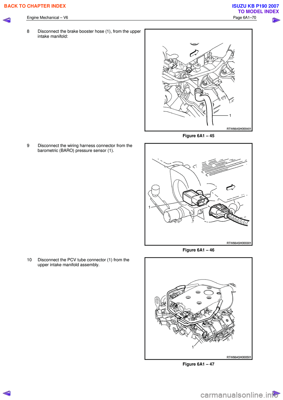
8 Disconnect the brake booster hose (1), from the upper
intake manifold:
Figure 6A1 – 45
9 Disconnect the wiring harness connector from the barometric (BARO) pressure sensor (1).
Figure 6A1 – 46
10 Disconnect the PCV tube connector (1) from the upper intake manifold assembly.
Figure 6A1 – 47
BACK TO CHAPTER INDEX
TO MODEL INDEX
ISUZU KB P190 2007
Page 3244 of 6020
Engine Management – V6 – General Information Page 6C1-1–2
3.9 Serial Data Communication System ................................................................................................................... 17
3.10 Self Diagnostics System ..................................................................................................................................... 17
3.11 Service Programming System ..................................................................................................... ....................... 17
3.12 Immobiliser System ............................................................................................................................................. 18
4 Component Description and Operation ............................................................................................ .19
4.1 A/C Refrigerant Pressure Sensor ....................................................................................................................... 19
4.2 Brake Pedal Switch Assembly ............................................................................................................................ 19
Stop Lamp and Initial Brake Apply Switch ....................................................................................... ................. 19
Stop Lamp Switch ............................................................................................................................................ 19
Initial Brake Apply Switch ..................................................................................................... ............................ 19
4.3 Barometric Pressure Sensor..................................................................................................... .......................... 20
4.4 Camshaft Position Sensor .................................................................................................................................. 20
4.5 Crankshaft Position Sensor ................................................................................................................................ 21
4.6 Clutch Pedal Switch Assembly – Manual Vehicles Only ............................................................................ ...... 22
4.7 Engine Control Module........................................................................................................................................ 22
4.8 Engine Coolant Temperature Sensor .............................................................................................. ................... 23
4.9 Electric Cooling Fans .......................................................................................................................................... 23
4.10 Engine Oil Level and Temperature Sensor ........................................................................................ ................ 24
Engine Oil Temperature Sensor ......................................................................................................................... 24
Engine Oil Level Sensor ...................................................................................................................................... 25
4.11 Engine Oil Pressure Sensor..................................................................................................... ........................... 25
4.12 Fuel Injectors........................................................................................................................................................ 26
4.13 Fuel Rail Assembly ............................................................................................................. ................................. 27
4.14 Heated Oxygen Sensors .......................................................................................................... ............................ 27
LSF 4.2 Two-step Planar Heated Oxygen Sensors .................................................................................. ......... 27
LSU 4.2 Wide-band Planar Heated Oxygen Sensors ................................................................................. ....... 29
4.15 Ignition Coil and Spark Plug ............................................................................................................................... 31
4.16 Intake Air Temperature Sensor .................................................................................................. ......................... 32
4.17 Knock Sensor ....................................................................................................................................................... 32
4.18 Mass Air Flow Sensor........................................................................................................... ............................... 33
Air Intake System ................................................................................................................................................. 33
Mass Air Flow Sensor........................................................................................................... ............................... 33
Construction ..................................................................................................................................................... 34
Operation ......................................................................................................................................................... 34
5 Abbreviations and Glossary of Terms ............................................................................................ ...35
BACK TO CHAPTER INDEX
TO MODEL INDEX
ISUZU KB P190 2007
Page 3261 of 6020
Engine Management – V6 – General Information Page 6C1-1–19
4 Component Description and
Operation
4.1 A/C Refrigerant Pressure Sensor
The engine control module (ECM) applies a positive 5 V reference voltage and ground to the air-conditioner (A/C)
refrigerant pressure sensor. The A/C refrigerant pressure sensor provides signal voltage to the ECM that is proportional
to the A/C refrigerant pressure. The ECM monitors the A/C refrigerant pressure sensor signal voltage to determine the
refrigerant pressure.
• The A/C refrigerant pressure sensor voltage increases as the refrigerant pressure increases.
• W hen the ECM detects the refrigerant pressure exceeds a predetermined value, the ECM activates the cooling
fans to reduce the refrigerant pressure.
• W hen the ECM detects the refrigerant pressure is too high or too low, the ECM disables the A/C clutch to protect
the A/C compressor from damage.
4.2 Brake Pedal Switch Assembly
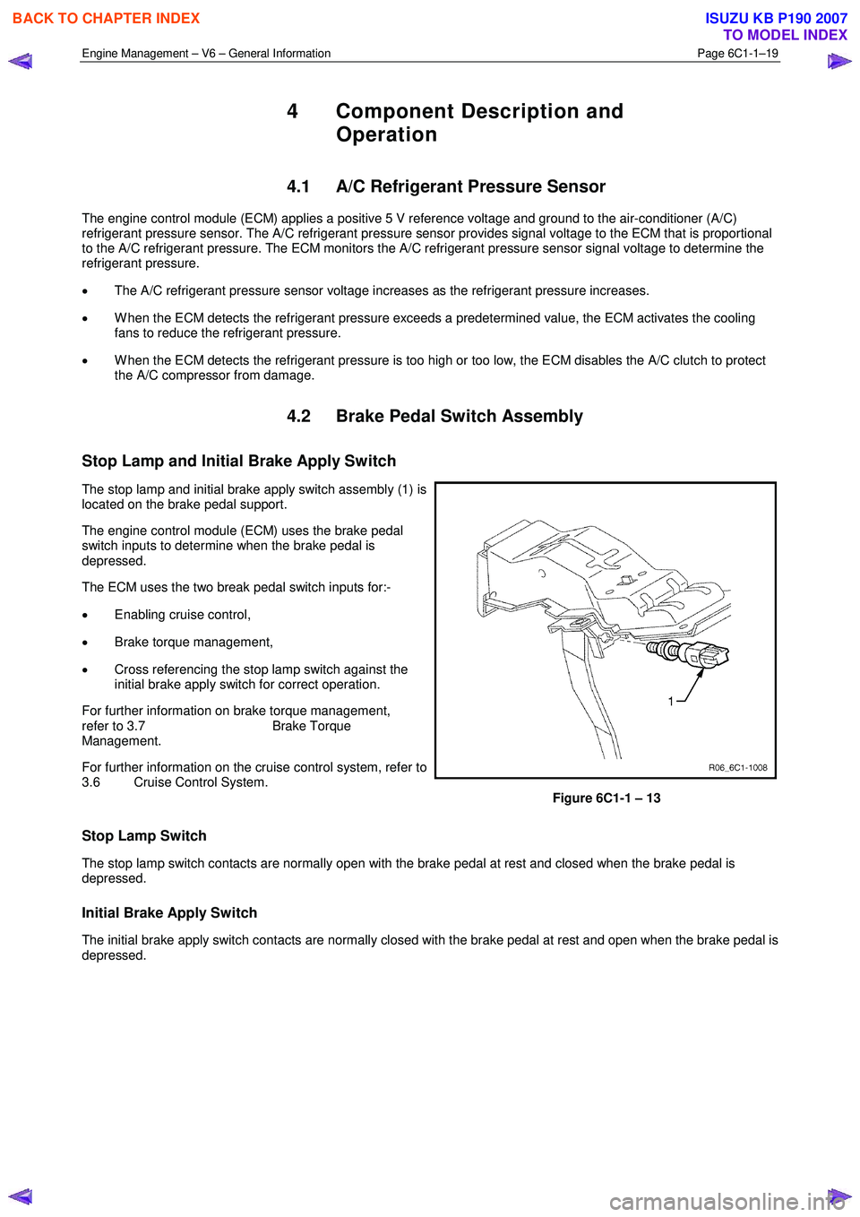
Stop Lamp and Initial Brake Apply Switch
The stop lamp and initial brake apply switch assembly (1) is
located on the brake pedal support.
The engine control module (ECM) uses the brake pedal
switch inputs to determine when the brake pedal is
depressed.
The ECM uses the two break pedal switch inputs for:-
• Enabling cruise control,
• Brake torque management,
• Cross referencing the stop lamp switch against the
initial brake apply switch for correct operation.
For further information on brake torque management,
refer to 3.7 Brake Torque
Management.
For further information on the cruise control system, refer to
3.6 Cruise Control System.
Figure 6C1-1 – 13
Stop Lamp Switch
The stop lamp switch contacts are normally open with the brake pedal at rest and closed when the brake pedal is
depressed.
Initial Brake Apply Switch
The initial brake apply switch contacts are normally closed with the brake pedal at rest and open when the brake pedal is
depressed.
BACK TO CHAPTER INDEX
TO MODEL INDEX
ISUZU KB P190 2007
Page 3293 of 6020
Engine Management – V6 – Diagnostics Page 6C1-2–15
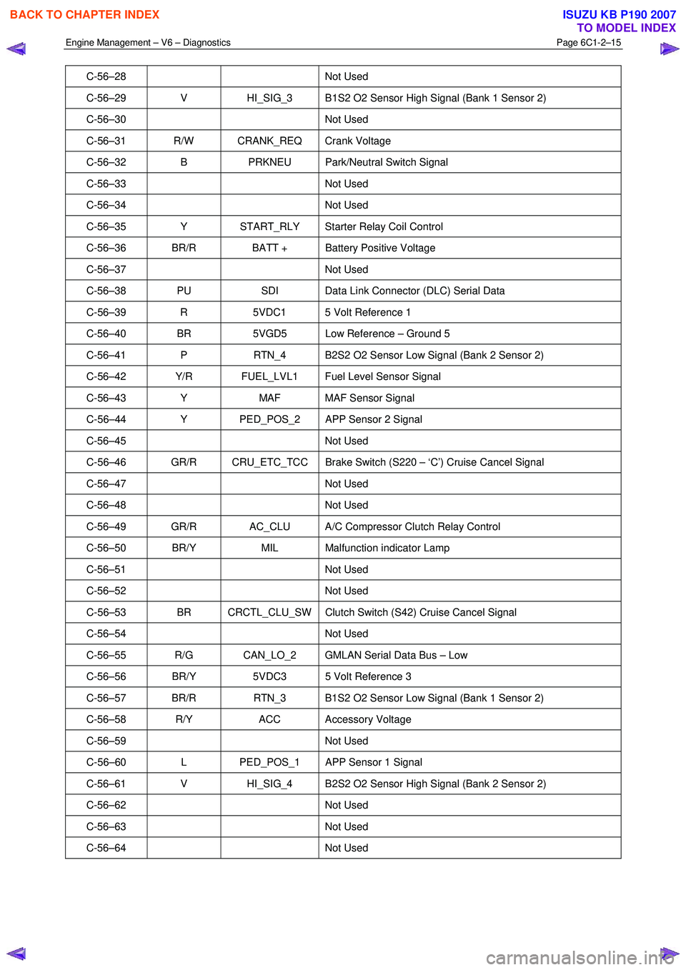
C-56–28 Not Used
C-56–29 V HI_SIG_3 B1S2 O2 Sensor High Signal (Bank 1 Sensor 2)
C-56–30 Not Used
C-56–31 R/W CRANK_REQ Crank Voltage
C-56–32 B PRKNEU Park/Neutral Switch Signal
C-56–33 Not Used
C-56–34 Not Used
C-56–35 Y START_RLY Starter Relay Coil Control
C-56–36 BR/R BATT + Battery Positive Voltage
C-56–37 Not Used
C-56–38 PU SDI Data Link Connector (DLC) Serial Data
C-56–39 R 5VDC1 5 Volt Reference 1
C-56–40 BR 5VGD5 Low Reference – Ground 5
C-56–41 P RTN_4 B2S2 O2 Sensor Low Signal (Bank 2 Sensor 2)
C-56–42 Y/R FUEL_LVL1 Fuel Level Sensor Signal
C-56–43 Y MAF MAF Sensor Signal
C-56–44 Y PED_POS_2 APP Sensor 2 Signal
C-56–45 Not Used
C-56–46 GR/R CRU_ETC_TCC Brake Switch (S220 – ‘C’) Cruise Cancel Signal
C-56–47 Not Used
C-56–48 Not Used
C-56–49 GR/R AC_CLU A/C Compressor Clutch Relay Control
C-56–50 BR/Y MIL Malfunction indicator Lamp
C-56–51 Not Used
C-56–52 Not Used
C-56–53 BR CRCTL_CLU_SW Clutch Switch (S42) Cruise Cancel Signal
C-56–54 Not Used
C-56–55 R/G CAN_LO_2 GMLAN Serial Data Bus – Low
C-56–56 BR/Y 5VDC3 5 Volt Reference 3
C-56–57 BR/R RTN_3 B1S2 O2 Sensor Low Signal (Bank 1 Sensor 2)
C-56–58 R/Y ACC Accessory Voltage
C-56–59 Not Used
C-56–60 L PED_POS_1 APP Sensor 1 Signal
C-56–61 V HI_SIG_4 B2S2 O2 Sensor High Signal (Bank 2 Sensor 2)
C-56–62 Not Used
C-56–63 Not Used
C-56–64 Not Used
BACK TO CHAPTER INDEX
TO MODEL INDEX
ISUZU KB P190 2007
Page 3312 of 6020
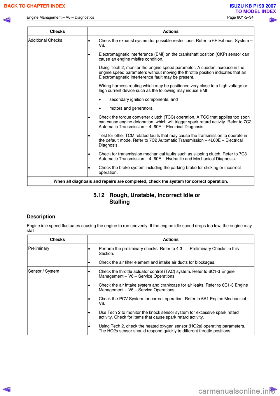
Engine Management – V6 – Diagnostics Page 6C1-2–34
Checks Actions
Additional Checks
• Check the exhaust system for possible restrictions. Refer to 6F Exhaust System –
V6.
• Electromagnetic interference (EMI) on the crankshaft position (CKP) sensor can
cause an engine misfire condition.
Using Tech 2, monitor the engine speed parameter. A sudden increase in the engine speed parameters without moving the throttle position indicates that an
Electromagnetic Interference fault may be present.
W iring harness routing which may be positioned very close to a high voltage or high current device such as the following may induce EMI:
• secondary ignition components, and
• motors and generators.
• Check the torque converter clutch (TCC) operation. A TCC that applies too soon
can cause engine detonation, which will trigger spark retard activity. Refer to 7C2
Automatic Transmission – 4L60E – Electrical Diagnosis.
• Test for other TCM related faults that may cause the transmission to operate in
the default mode. Refer to 7C2 Automatic Transmission – 4L60E – Electrical
Diagnosis.
• Check for transmission mechanical faults such as slipping clutch. Refer to 7C3
Automatic Transmission – 4L60E – Hydraulic and Mechanical Diagnosis.
• Check the brake system including the parking brake for sticking or incorrect
operation.
When all diagnosis and repairs are completed, check the system for correct operation.
5.12 Rough, Unstable, Incorrect Idle or
Stalling
Description
Engine idle speed fluctuates causing the engine to run unevenly. If the engine idle speed drops too low, the engine may
stall.
Checks Actions
Preliminary • Perform the preliminary checks. Refer to 4.3 Preliminary Checks in this
Section.
• Check the air filter element and intake air ducts for blockages.
Sensor / System
• Check the throttle actuator control (TAC) system. Refer to 6C1-3 Engine
Management – V6 – Service Operations.
• Check the air intake system and crankcase for air leaks. Refer to 6C1-3 Engine
Management – V6 – Service Operations.
• Check the PCV System for correct operation. Refer to 6A1 Engine Mechanical –
V6.
• Use Tech 2 to monitor the knock sensor system for excessive spark retard
activity. Check for items that cause spark retard activity.
• Using Tech 2, check the heated oxygen sensor (HO2s) operating parameters.
The HO2s sensor should respond quickly to different throttle positions.
BACK TO CHAPTER INDEX
TO MODEL INDEX
ISUZU KB P190 2007
Page 3333 of 6020
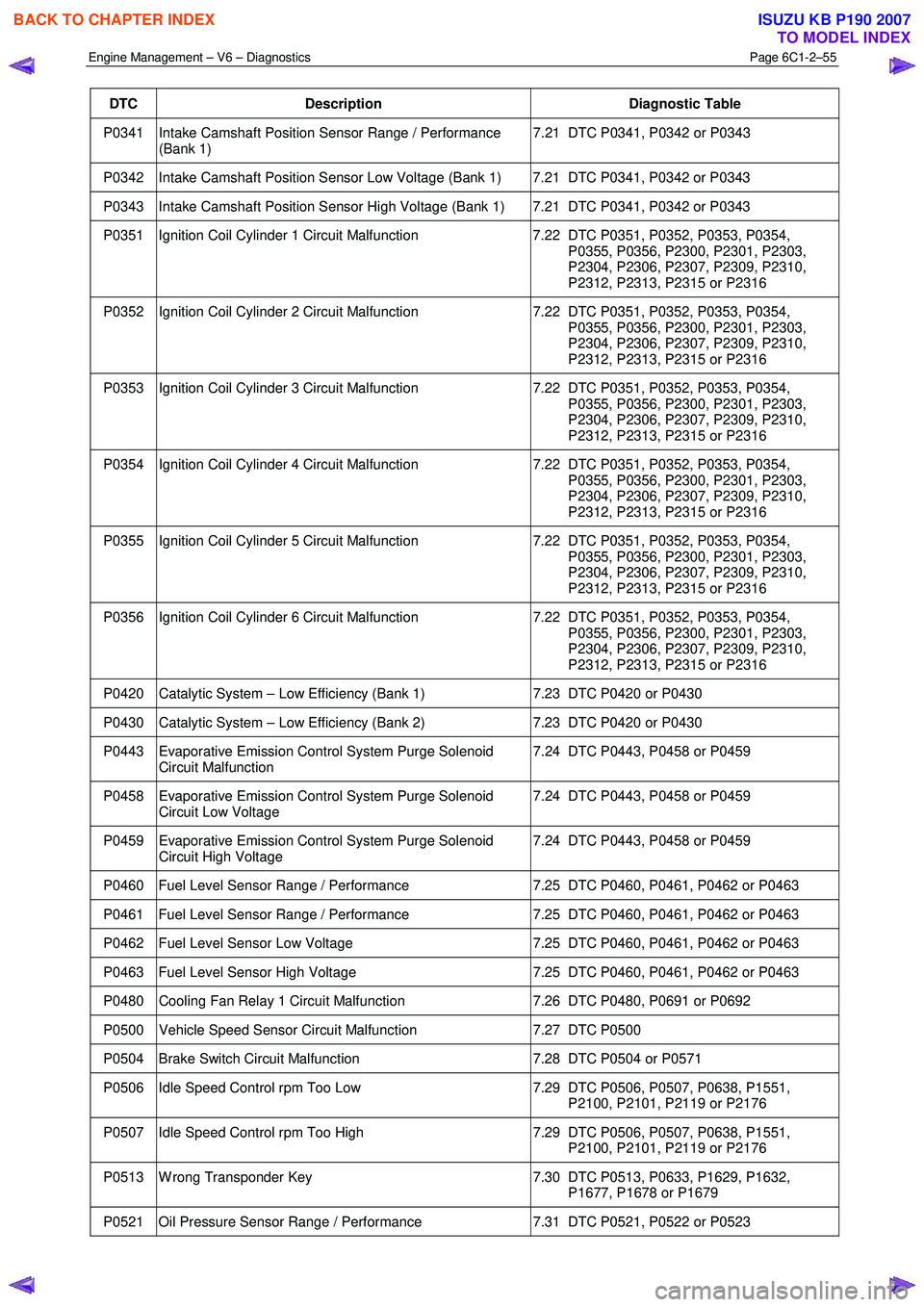
Engine Management – V6 – Diagnostics Page 6C1-2–55
DTC Description Diagnostic Table
P0341 Intake Camshaft Position Sensor Range / Performance
(Bank 1) 7.21 DTC P0341, P0342 or P0343
P0342 Intake Camshaft Position Sensor Low Voltage (Bank 1) 7.21 DTC P0341, P0342 or P0343
P0343 Intake Camshaft Position Sensor High Voltage (Bank 1) 7.21 DTC P0341, P0342 or P0343
P0351 Ignition Coil Cylinder 1 Circuit Malfunction
7.22 DTC P0351, P0352, P0353, P0354,
P0355, P0356, P2300, P2301, P2303,
P2304, P2306, P2307, P2309, P2310,
P2312, P2313, P2315 or P2316
P0352 Ignition Coil Cylinder 2 Circuit Malfunction 7.22 DTC P0351, P0352, P0353, P0354,
P0355, P0356, P2300, P2301, P2303,
P2304, P2306, P2307, P2309, P2310,
P2312, P2313, P2315 or P2316
P0353 Ignition Coil Cylinder 3 Circuit Malfunction 7.22 DTC P0351, P0352, P0353, P0354,
P0355, P0356, P2300, P2301, P2303,
P2304, P2306, P2307, P2309, P2310,
P2312, P2313, P2315 or P2316
P0354 Ignition Coil Cylinder 4 Circuit Malfunction 7.22 DTC P0351, P0352, P0353, P0354,
P0355, P0356, P2300, P2301, P2303,
P2304, P2306, P2307, P2309, P2310,
P2312, P2313, P2315 or P2316
P0355 Ignition Coil Cylinder 5 Circuit Malfunction 7.22 DTC P0351, P0352, P0353, P0354,
P0355, P0356, P2300, P2301, P2303,
P2304, P2306, P2307, P2309, P2310,
P2312, P2313, P2315 or P2316
P0356 Ignition Coil Cylinder 6 Circuit Malfunction 7.22 DTC P0351, P0352, P0353, P0354,
P0355, P0356, P2300, P2301, P2303,
P2304, P2306, P2307, P2309, P2310,
P2312, P2313, P2315 or P2316
P0420 Catalytic System – Low Efficiency (Bank 1) 7.23 DTC P0420 or P0430
P0430 Catalytic System – Low Efficiency (Bank 2) 7.23 DTC P0420 or P0430
P0443 Evaporative Emission Control System Purge Solenoid
Circuit Malfunction 7.24 DTC P0443, P0458 or P0459
P0458 Evaporative Emission Control System Purge Solenoid
Circuit Low Voltage 7.24 DTC P0443, P0458 or P0459
P0459 Evaporative Emission Control System Purge Solenoid
Circuit High Voltage 7.24 DTC P0443, P0458 or P0459
P0460 Fuel Level Sensor Range / Performance
7.25 DTC P0460, P0461, P0462 or P0463
P0461 Fuel Level Sensor Range / Performance 7.25 DTC P0460, P0461, P0462 or P0463
P0462 Fuel Level Sensor Low Voltage 7.25 DTC P0460, P0461, P0462 or P0463
P0463 Fuel Level Sensor High Voltage 7.25 DTC P0460, P0461, P0462 or P0463
P0480 Cooling Fan Relay 1 Circuit Malfunction 7.26 DTC P0480, P0691 or P0692
P0500 Vehicle Speed Sensor Circuit Malfunction 7.27 DTC P0500
P0504 Brake Switch Circuit Malfunction 7.28 DTC P0504 or P0571
P0506 Idle Speed Control rpm Too Low 7.29 DTC P0506, P0507, P0638, P1551,
P2100, P2101, P2119 or P2176
P0507 Idle Speed Control rpm Too High 7.29 DTC P0506, P0507, P0638, P1551,
P2100, P2101, P2119 or P2176
P0513 W rong Transponder Key 7.30 DTC P0513, P0633, P1629, P1632,
P1677, P1678 or P1679
P0521 Oil Pressure Sensor Range / Performance 7.31 DTC P0521, P0522 or P0523
BACK TO CHAPTER INDEX
TO MODEL INDEX
ISUZU KB P190 2007
Page 3334 of 6020
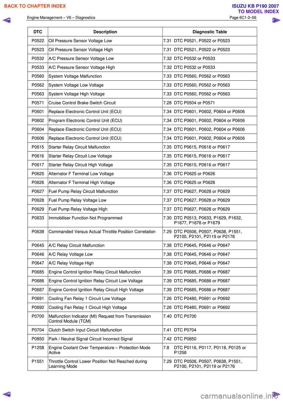
Engine Management – V6 – Diagnostics Page 6C1-2–56
DTC Description Diagnostic Table
P0522 Oil Pressure Sensor Voltage Low 7.31 DTC P0521, P0522 or P0523
P0523 Oil Pressure Sensor Voltage High 7.31 DTC P0521, P0522 or P0523
P0532 A/C Pressure Sensor Voltage Low 7.32 DTC P0532 or P0533
P0533 A/C Pressure Sensor Voltage High 7.32 DTC P0532 or P0533
P0560 System Voltage Malfunction 7.33 DTC P0560, P0562 or P0563
P0562 System Voltage Low Voltage 7.33 DTC P0560, P0562 or P0563
P0563 System Voltage High Voltage 7.33 DTC P0560, P0562 or P0563
P0571 Cruise Control Brake Switch Circuit 7.28 DTC P0504 or P0571
P0601 Replace Electronic Control Unit (ECU) 7.34 DTC P0601, P0602, P0604 or P0606
P0602 Program Electronic Control Unit (ECU) 7.34 DTC P0601, P0602, P0604 or P0606
P0604 Replace Electronic Control Unit (ECU) 7.34 DTC P0601, P0602, P0604 or P0606
P0606 Replace Electronic Control Unit (ECU) 7.34 DTC P0601, P0602, P0604 or P0606
P0615 Starter Relay Circuit Malfunction 7.35 DTC P0615, P0616 or P0617
P0616 Starter Relay Circuit Low Voltage 7.35 DTC P0615, P0616 or P0617
P0617 Starter Relay Circuit High Voltage 7.35 DTC P0615, P0616 or P0617
P0625 Alternator F Terminal Low Voltage 7.36 DTC P0625 or P0626
P0626 Alternator F Terminal High Voltage 7.36 DTC P0625 or P0626
P0627 Fuel Pump Relay Circuit Malfunction 7.37 DTC P0627, P0628 or P0629
P0628 Fuel Pump Relay Voltage Low 7.37 DTC P0627, P0628 or P0629
P0629 Fuel Pump Relay Voltage High 7.37 DTC P0627, P0628 or P0629
P0633 Immobiliser Function Not Programmed 7.30 DTC P0513, P0633, P1629, P1632,
P1677, P1678 or P1679
P0638 Commanded Versus Actual Throttle Position Correlation 7.29 DTC P0506, P0507, P0638, P1551, P2100, P2101, P2119 or P2176
P0645 A/C Relay Circuit Malfunction 7.38 DTC P0645, P0646 or P0647
P0646 A/C Relay Voltage Low 7.38 DTC P0645, P0646 or P0647
P0647 A/C Relay Voltage High 7.38 DTC P0645, P0646 or P0647
P0685 Engine Control Ignition Relay Circuit Malfunction 7.39 DTC P0685, P0686 or P0687
P0686 Engine Control Ignition Relay Circuit Low Voltage 7.39 DTC P0685, P0686 or P0687
P0687 Engine Control Ignition Relay Circuit High Voltage 7.39 DTC P0685, P0686 or P0687
P0691 Cooling Fan Relay 1 Circuit Low Voltage 7.26 DTC P0480, P0691 or P0692
P0692 Cooling Fan Relay 1 Circuit High Voltage 7.26 DTC P0480, P0691 or P0692
P0700 Malfunction Indicator (MI) Request from Transmission
Control Module (TCM) 7.40 DTC P0700
P0704 Clutch Switch Input Circuit Malfunction
7.41 DTC P0704
P0850 Park / Neutral Signal Circuit Incorrect Signal 7.42 DTC P0850
P1258 Engine Coolant Over Temperature – Protection Mode
Active 7.8 DTC P0116, P0117, P0118, P0125 or
P1258
P1551 Throttle Control Lower Position Not Reached during Learning Mode 7.29 DTC P0506, P0507, P0638, P1551,
P2100, P2101, P2119 or P2176
BACK TO CHAPTER INDEX
TO MODEL INDEX
ISUZU KB P190 2007
Page 3348 of 6020
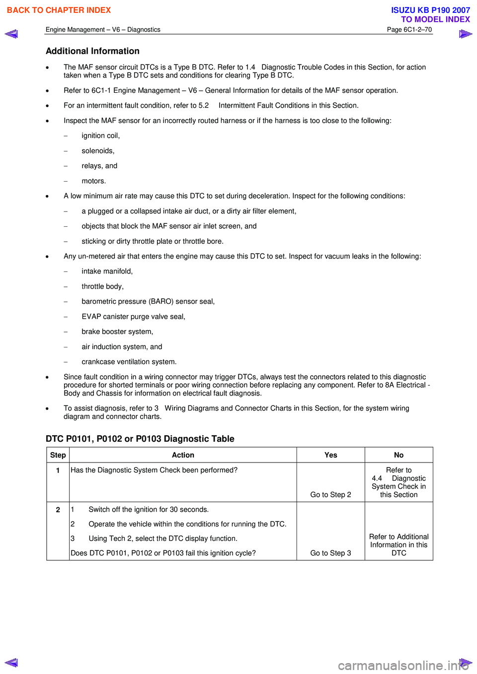
Engine Management – V6 – Diagnostics Page 6C1-2–70
Additional Information
• The MAF sensor circuit DTCs is a Type B DTC. Refer to 1.4 Diagnostic Trouble Codes in this Section, for action
taken when a Type B DTC sets and conditions for clearing Type B DTC.
• Refer to 6C1-1 Engine Management – V6 – General Information for details of the MAF sensor operation.
• For an intermittent fault condition, refer to 5.2 Intermittent Fault Conditions in this Section.
• Inspect the MAF sensor for an incorrectly routed harness or if the harness is too close to the following:
− ignition coil,
− solenoids,
− relays, and
− motors.
• A low minimum air rate may cause this DTC to set during deceleration. Inspect for the following conditions:
− a plugged or a collapsed intake air duct, or a dirty air filter element,
− objects that block the MAF sensor air inlet screen, and
− sticking or dirty throttle plate or throttle bore.
• Any un-metered air that enters the engine may cause this DTC to set. Inspect for vacuum leaks in the following:
− intake manifold,
− throttle body,
− barometric pressure (BARO) sensor seal,
− EVAP canister purge valve seal,
− brake booster system,
− air induction system, and
− crankcase ventilation system.
• Since fault condition in a wiring connector may trigger DTCs, always test the connectors related to this diagnostic
procedure for shorted terminals or poor wiring connection before replacing any component. Refer to 8A Electrical -
Body and Chassis for information on electrical fault diagnosis.
• To assist diagnosis, refer to 3 W iring Diagrams and Connector Charts in this Section, for the system wiring
diagram and connector charts.
DTC P0101, P0102 or P0103 Diagnostic Table
Step Action Yes No
1 Has the Diagnostic System Check been performed?
Go to Step 2 Refer to
4.4 Diagnostic
System Check in this Section
2 1 Switch off the ignition for 30 seconds.
2 Operate the vehicle within the conditions for running the DTC.
3 Using Tech 2, select the DTC display function.
Does DTC P0101, P0102 or P0103 fail this ignition cycle? Go to Step 3 Refer to Additional
Information in this DTC
BACK TO CHAPTER INDEX
TO MODEL INDEX
ISUZU KB P190 2007