2007 ISUZU KB P190 brake sensor
[x] Cancel search: brake sensorPage 3979 of 6020
TRANSMISSION CONTROL SYSTEM (AW30–40LE) 7A2-13
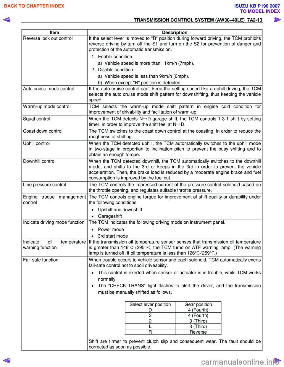
Item Description
Reverse lock out control If the select lever is moved to "R" position during forward driving, the TCM prohibits
reverse driving by turn off the S1 and turn on the S2 for prevention of danger and
protection of the automatic transmission.
1. Enable condition a) Vehicle speed is more than 11km/h (7mph).
2. Disable condition a) Vehicle speed is less than 9km/h (6mph).
b) W hen except "R" position is detected.
Auto cruise mode control If the auto cruise control can’t keep the setting speed like a uphill driving, the TCM selects the auto cruise mode shift pattern for downshifting, thus keeping the vehicle
speed.
W arm-up mode control TCM selects the warm-up mode shift pattern in engine cold condition for improvement of drivability and facilitation of warm-up.
Squat control W hen the TCM detects N→D garage shift, the TCM controls 1-3-1 shift by setting
timer, in order to improve the shift feel at N →D.
Coast down control The TCM switches to the coast down control at the coasting, in order to reduce the
roughness of shifting.
Uphill control W hen the TCM detected uphill, the TCM automatically switches to the uphill mode
in two-stage in proportion to inclination pitch to prevent the busy shifting and to
obtain an enough torque.
Downhill control W hen the TCM detected downhill, the TCM automatically switches to the downhill
mode, and shifts to the 3rd or keeps in the 3rd in order to prevent the vehicle
acceleration. Then, the brake load is reduced by a moderate engine brake and fuel
consumption is improved by the fuel cut.
Line pressure control The TCM controls the impressed current of the pressure control solenoid based on the throttle opening, and regulates suitable throttle pressure.
Engine truque management
control The TCM controls engine torque for improvement of shift quality or durability under
the following conditions.
• Upshift and downshift
• Garageshift
Indicate driving mode function The TCM indicates the following driving mode on instrument panel.
• Power mode
• 3rd start mode
Indicate oil temperature
warning function If the transmission oil temperature sensor senses that transmission oil temperature
is greater than 146 °C (295 °F) , the TCM turns on ATF warning lamp. (The warning
lamp is turned off, if oil temperature is less than 126 °C/ 259 °F .)
Fail-safe function W hen trouble occurs to vehicle sensor and each solenoid, TCM automatically exerts
fail-safe control not to spoil driveability.
• This control is exerted when sensor or actuator is in trouble, while TCM works
normally.
• The "CHECK TRANS" light flashes to alert the driver, and the transmission
must be manually shifted as follows.
Select lever position Gear position
D 4 (Fourth)
3 4 (Fourth)
2 3 (Third)
L 3 (Third)
R Reverse
Shift are firmer to prevent clutch slip and consequent wear. The fault should be
corrected as soon as possible.
BACK TO CHAPTER INDEX
TO MODEL INDEX
ISUZU KB P190 2007
Page 4060 of 6020
7A2-94 TRANSMISSION CONTROL SYSTEM (AW30–40LE)
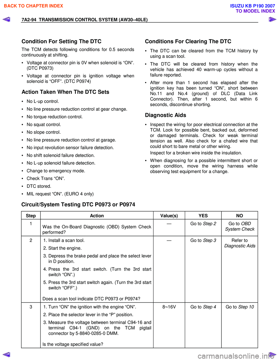
Condition For Setting The DTC
The TCM detects following conditions for 0.5 seconds
continuously at shifting.
• Voltage at connector pin is 0V when solenoid is “ON”.
(DTC P0973)
• Voltage at connector pin is ignition voltage when
solenoid is “OFF”. (DTC P0974)
Action Taken When The DTC Sets
• No L-up control.
• No line pressure reduction control at gear change.
• No torque reduction control.
• No squat control.
• No slope control.
• No line pressure reduction control at garage.
• No input revolution sensor failure detection.
• No shift solenoid failure detection.
• No L-up solenoid failure detection.
• Change to emergency mode.
• Check Trans “ON”.
• DTC stored.
• MIL request “ON”. (EURO 4 only)
Conditions For Clearing The DTC
•
The DTC can be cleared from the TCM history by
using a scan tool.
• The DTC will be cleared from history when the
vehicle has achieved 40 warm-up cycles without a
failure reported.
•
After more than 1 second has elapsed after the
ignition key has been turned “ON”, short between
No.11 and No.4 (ground) of DLC (Data Link
Connector). Then, after 1 second, but within 6
seconds, discontinue shorting.
Diagnostic Aids
• Inspect the wiring for poor electrical connection at the
TCM. Look for possible bent, backed out, deformed
or damaged terminals. Check for weak terminal
tension as well. Also check for a chafed wire that
could short to bare metal or other wiring.
Inspect for a broken wire inside the insulation.
• W hen diagnosing for a possible intermittent short o
r
open condition, move the wiring harness while
observing test equipment for a change.
Circuit/System Testing DTC P0973 or P0974
Step Action Value(s) YES NO
1
W as the On-Board Diagnostic (OBD) System Check
performed? — Go to
Step 2 Go to OBD
System Check
2 1. Install a scan tool.
2. Start the engine.
3. Depress the brake pedal and place the select lever in D position.
4. Press the 3rd start switch. (Turn the 3rd start switch “ON”.)
5. Press the 3rd start switch again. (Turn the 3rd start switch “OFF”.)
Does a scan tool indicate DTC P0973 or P0974? — Go to
Step 3 Refer to
Diagnostic Aids
3 1. Turn “ON” the ignition with the engine “ON”.
2. Place the selector lever in the “P” position.
3. Measure the voltage between terminal C94-16 and terminal C94-1 (GND) on the TCM pigtail
connector by 5-8840-0285-0 DMM.
Is the voltage specified value? 8∼16V Go to
Step 4 Go to Step 10
BACK TO CHAPTER INDEX
TO MODEL INDEX
ISUZU KB P190 2007
Page 4064 of 6020
7A2-98 TRANSMISSION CONTROL SYSTEM (AW30–40LE)
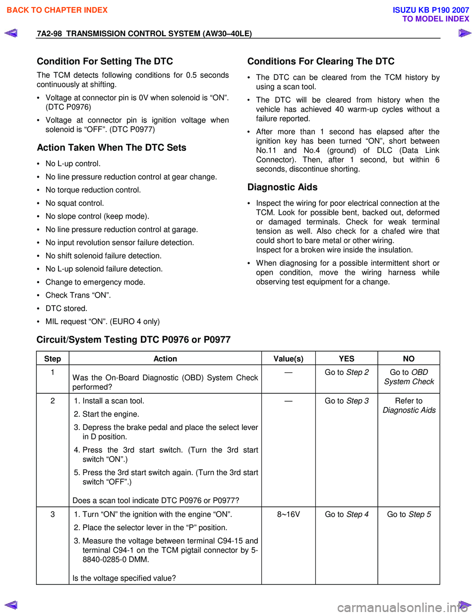
Condition For Setting The DTC
The TCM detects following conditions for 0.5 seconds
continuously at shifting.
• Voltage at connector pin is 0V when solenoid is “ON”.
(DTC P0976)
• Voltage at connector pin is ignition voltage when
solenoid is “OFF”. (DTC P0977)
Action Taken When The DTC Sets
• No L-up control.
• No line pressure reduction control at gear change.
• No torque reduction control.
• No squat control.
• No slope control (keep mode).
• No line pressure reduction control at garage.
• No input revolution sensor failure detection.
• No shift solenoid failure detection.
• No L-up solenoid failure detection.
• Change to emergency mode.
• Check Trans “ON”.
• DTC stored.
• MIL request “ON”. (EURO 4 only)
Conditions For Clearing The DTC
•
The DTC can be cleared from the TCM history by
using a scan tool.
• The DTC will be cleared from history when the vehicle has achieved 40 warm-up cycles without a
failure reported.
•
After more than 1 second has elapsed after the
ignition key has been turned “ON”, short between
No.11 and No.4 (ground) of DLC (Data Link
Connector). Then, after 1 second, but within 6
seconds, discontinue shorting.
Diagnostic Aids
• Inspect the wiring for poor electrical connection at the
TCM. Look for possible bent, backed out, deformed
or damaged terminals. Check for weak terminal
tension as well. Also check for a chafed wire that
could short to bare metal or other wiring.
Inspect for a broken wire inside the insulation.
• W hen diagnosing for a possible intermittent short o
r
open condition, move the wiring harness while
observing test equipment for a change.
Circuit/System Testing DTC P0976 or P0977
Step Action Value(s) YES NO
1
W as the On-Board Diagnostic (OBD) System Check
performed? — Go to
Step 2 Go to OBD
System Check
2 1. Install a scan tool.
2. Start the engine.
3. Depress the brake pedal and place the select lever in D position.
4. Press the 3rd start switch. (Turn the 3rd start switch “ON”.)
5. Press the 3rd start switch again. (Turn the 3rd start switch “OFF”.)
Does a scan tool indicate DTC P0976 or P0977? — Go to
Step 3 Refer to
Diagnostic Aids
3 1. Turn “ON” the ignition with the engine “ON”.
2. Place the selector lever in the “P” position.
3. Measure the voltage between terminal C94-15 and terminal C94-1 on the TCM pigtail connector by 5-
8840-0285-0 DMM.
Is the voltage specified value? 8∼16V Go to
Step 4 Go to Step 5
BACK TO CHAPTER INDEX
TO MODEL INDEX
ISUZU KB P190 2007
Page 4086 of 6020
ON-VEHICLE SERVICE (AW30–40LE) 7A3-1
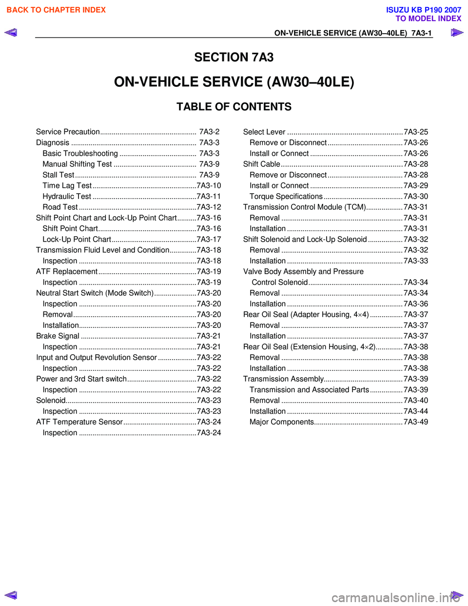
SECTION 7A3
ON-VEHICLE SERVICE (AW30–40LE)
TABLE OF CONTENTS
Service Precaution .................................................. 7A3-2
Diagnosis ................................................................. 7A3-3
Basic Troubleshooting ........................................ 7A3-3
Manual Shifting Test ........................................... 7A3-9
Stall Test ............................................................... 7A3-9
Time Lag Test ...................................................... 7A3-10
Hydraulic Test ...................................................... 7A3-11
Road Test ............................................................. 7A3-12
Shift Point Chart and Lock-Up Point Chart ..........7A3-16
Shift Point Chart ................................................... 7A3-16
Lock-Up Point Chart ............................................ 7A3-17
Transmission Fluid Level and Condition ..............7A3-18
Inspection ............................................................. 7A3-18
ATF Replacement ................................................... 7A3-19
Inspection ............................................................. 7A3-19
Neutral Start Switch (Mode Switch) ......................7A3-20
Inspection ............................................................. 7A3-20
Removal ................................................................ 7A3-20
Installation ............................................................. 7A3-20
Brake Signal ............................................................ 7A3-21
Inspection ............................................................. 7A3-21
Input and Output Revolution Sensor ....................7A3-22
Inspection ............................................................. 7A3-22
Power and 3rd Start switch ....................................7A3-22
Inspection ............................................................. 7A3-22
Solenoid .................................................................... 7A3-23
Inspection ............................................................. 7A3-23
ATF Temperature Sensor ......................................7A3-24
Inspection ............................................................. 7A3-24
Select Lever ....................................................... 7A3-25 Remove or Disconnect .......................................7A3-26
Install or Connect ................................................ 7A3-26
Shift Cable .......................................................... 7A3-28 Remove or Disconnect .......................................7A3-28
Install or Connect ................................................ 7A3-29
Torque Specifications ......................................... 7A3-30
Transmission Control Module (TCM) ...................7A3-31
Removal ............................................................... 7A3-31
Installation ............................................................ 7A3-31
Shift Solenoid and Lock-Up Solenoid ..................7A3-32
Removal ............................................................... 7A3-32
Installation ............................................................ 7A3-33
Valve Body Assembly and Pressure Control Solenoid ................................................. 7A3-34
Removal ............................................................... 7A3-34
Installation ............................................................ 7A3-36
Rear Oil Seal (Adapter Housing, 4 ×4) ................. 7A3-37
Removal ............................................................... 7A3-37
Installation ............................................................ 7A3-37
Rear Oil Seal (Extension Housing, 4 ×2) .............. 7A3-38
Removal ............................................................... 7A3-38
Installation ............................................................ 7A3-38
Transmission Assembly .........................................7A3-39
Transmission and Associated Parts .................7A3-39
Removal ............................................................... 7A3-40
Installation ............................................................ 7A3-44
Major Components .............................................. 7A3-49
BACK TO CHAPTER INDEX
TO MODEL INDEX
ISUZU KB P190 2007
Page 4144 of 6020
UNIT REPAIR (AW30–40LE) 7A4–9
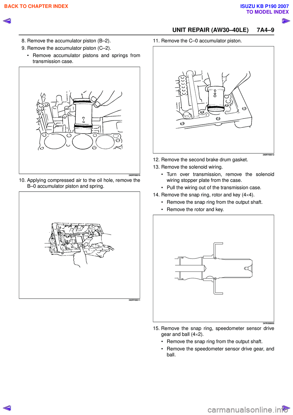
8. Remove the accumulator piston (B–2).
9. Remove the accumulator piston (C –2).
Remove accumulator pistons and springs from
transmission case.
240RY00010
10. Applying compressed air to the oil hole, remove the B–0 accumulator piston and spring.
240RY00011
11. Remove the C –0 accumulator piston.
240RY00012
12. Remove the second brake drum gasket.
13. Remove the solenoid wiring.
Turn over transmission, remove the solenoid
wiring stopper plate from the case.
Pull the wiring out of the transmission case.
14. Remove the snap ring, rotor and key (4 ×4).
Remove the snap ring from the output shaft.
Remove the rotor and key.
247R200002
15. Remove the snap ring, speedometer sensor drive
gear and ball (4 ×2).
Remove the snap ring from the output shaft.
Remove the speedometer sensor drive gear, and
ball.
BACK TO CHAPTER INDEX
TO MODEL INDEX
ISUZU KB P190 2007
Page 4240 of 6020
CONSTRUCTION AND FUNCTION 7A1-1
SECTION 7A1
CONSTRUCTION AND FUNCTION (JR405E)
TABLE OF CONTENTS
PAGE
Description ................................................................................................................... ...7A1- 3
Construction ...............................................................................................................7A1 - 3
Main Data and Specification .....................................................................................7A1- 4
Number Plate Location ..............................................................................................7A1- 5
Electronic Control Components Location ...............................................................7A1- 6
Transmission Control Module (TCM) Peripheral Circuit .........................................7A1- 7
Structure and Function of Component .........................................................................7A1- 8
Torque Converter (with Lock-up Function) .............................................................7A1- 8
Oil Pump .....................................................................................................................7 A1- 9
Input Shaft ..................................................................................................................7 A1- 10
Output Shaft ...............................................................................................................7A1 - 10
Gear Shifting Mechanism ..........................................................................................7A1- 10
Control Valve ..............................................................................................................7A1 - 14
Oil Passage .................................................................................................................7A 1- 19
Parking Function ........................................................................................................7A1- 2 0
Inhibitor Switch ..........................................................................................................7A1- 21
Turbine Sensor ...........................................................................................................7A1- 22
Speed Sensor .............................................................................................................7A1- 22
Accelerator Pedal Position Sensor ..........................................................................7A1- 23
Engine Speed Sensor (=CKP Sensor) ......................................................................7A1- 23
Brake Switch ..............................................................................................................7A1- 24
Mode Select Switch ...................................................................................................7A1- 24
Transmission Control Module (TCM) .......................................................................7A1- 25
Control Mechanism ........................................................................................................7A1- 26
Content of Function and Control ..............................................................................7A1- 26
Control Item, Input and Output .................................................................................7A1- 29
Line Pressure Control ................................................................................................7A1- 30
Lock-up Control .........................................................................................................7A1- 3 0
Direct Electric Shift Control (DESC) .........................................................................7A1- 31
BACK TO CHAPTER INDEX
TO MODEL INDEX
ISUZU KB P190 2007
Page 4242 of 6020
CONSTRUCTION AND FUNCTION 7A1-3
DESCRIPTION
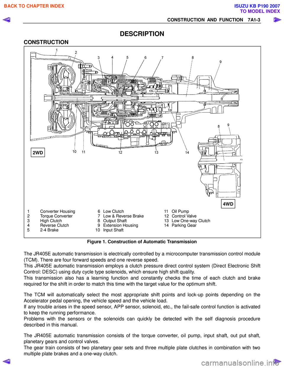
CONSTRUCTION
1 Converter Housing 6 Low Clutch 11 Oil Pump
2 Torque Converter 7 Low & Reverse Brake 12 Control Valve
3 High Clutch 8 Output Shaft 13 Low One-way Clutch
4 Reverse Clutch 9 Extension Housing 14 Parking Gear
5 2-4 Brake 10 Input Shaft
Figure 1. Construction of Automatic Transmission
The JR405E automatic transmission is electrically controlled by a microcomputer transmission control module
(TCM). There are four forward speeds and one reverse speed.
This JR405E automatic transmission employs a clutch pressure direct control system (Direct Electronic Shift
Control: DESC) using duty cycle type solenoids, which ensure high shift quality.
This transmission also has a learning function and constantly checks the time of each clutch and brake
required for the shift in order to match this time with the target value for the optimum shift.
The TCM will automatically select the most appropriate shift points and lock-up points depending on the
Accelerator pedal opening, the vehicle speed and the vehicle load.
If any trouble arises in the speed sensor, APP sensor, solenoid, etc., the fail-safe control function is activated
to keep the running performance.
Problems with the sensors or the solenoids can quickly be detected with the self diagnosis procedure
described in this manual.
The JR405E automatic transmission consists of the torque converter, oil pump, input shaft, out put shaft,
planetary gears and control valves.
The gear train consists of two planetary gear sets and three multiple plate clutches in combination with two
multiple plate brakes and a one-way clutch.
2WD
4WD
BACK TO CHAPTER INDEX
TO MODEL INDEX
ISUZU KB P190 2007
Page 4245 of 6020
7A1-6 CONSTRUCTION AND FUNCTION
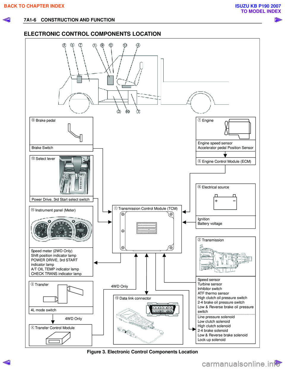
ELECTRONIC CONTROL COMPONENTS LOCATION
4WD Only 4W D Only
Instrument panel (Meter)
Speed meter (2WD Only)
Shift position indicator lamp
POWER DRIVE, 3rd START
indicator lamp
A/T OIL TEMP indicator lamp
CHECK TRANS indicator lam
p
Brake pedal
Brake Switch
Transmission Control Module (TCM)
Electrical source
Ignition
Battery voltage
Speed sensor
Turbine sensor
Inhibitor switch
ATF thermo sensor
High clutch oil pressure switch
2-4 brake oil pressure switch
Low & Reverse brake oil pressure
switch
Line pressure solenoid
Low clutch solenoid
High clutch solenoid
2-4 brake solenoid
Low & Reverse brake solenoid
Lock-up solenoid
Transmission
Transfer Control Module
Transfer
4L mode switch
Engine
Engine speed sensor
Accelerator pedal Position Sensor
Engine Control Module (ECM)
Data link connector
Select lever
Power Drive
, 3rd Start select switch
Figure 3. Electronic Control Components Location
BACK TO CHAPTER INDEX
TO MODEL INDEX
ISUZU KB P190 2007