2007 ISUZU KB P190 brake sensor
[x] Cancel search: brake sensorPage 4383 of 6020
TRANSMISSION CONTROL SYSTEM (JR405E) 7A2-99
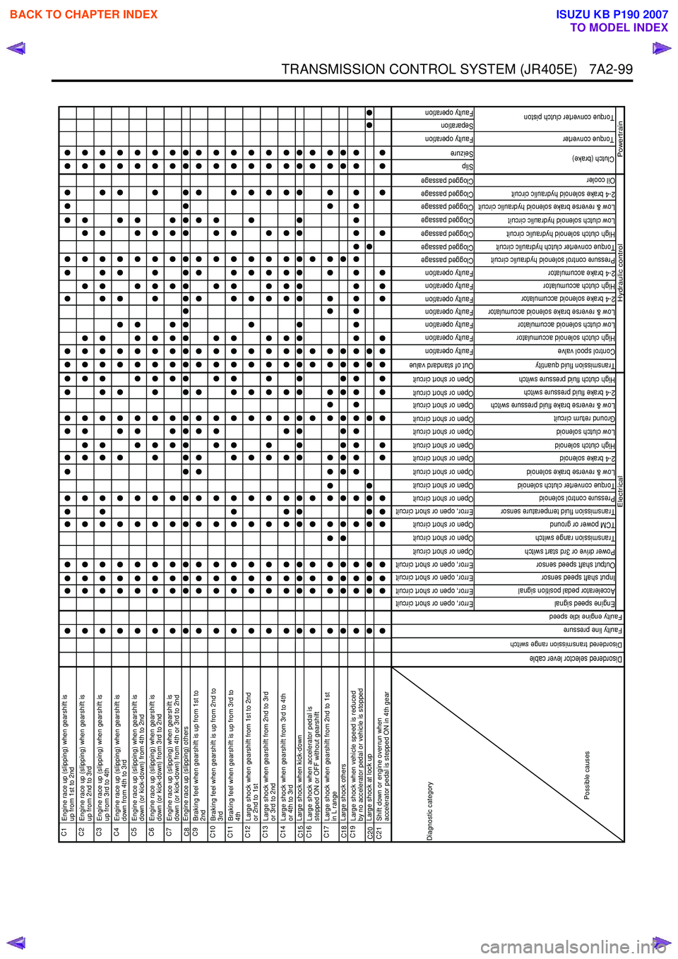
C1
Engine race up (slipping) when gearshift is
up from 1st to 2nd
C2
Engine race up (slipping) when gearshift is
up from 2nd to 3rd
C3
Engine race up (slipping) when gearshift is
up from 3rd to 4th
C4
Engine race up (slipping) when gearshift is
down from 4th to 3rd
C5
Engine race up (slipping) when gearshift is
down (or kick-down) from 4th to 2nd
C6
Engine race up (slipping) when gearshift is
down (or kick-down) from 3rd to 2nd
C7
Engine race up (slipping) when gearshift is
down (or kick-down) from 4th or 3rd to 2nd
C8 Engine race up (slipping) othersC9
Braking feel when gearshift is up from 1st to
2nd
C10
Braking feel when gearshift is up from 2nd to
3rd
C11
Braking feel when gearshift is up from 3rd to
4th
C12
Large shock when gearshift from 1st to 2nd
or 2nd to 1st
C13
Large shock when gearshift from 2nd to 3rd
or 3rd to 2nd
C14
Large shock when gearshift from 3rd to 4th
or 4th to 3rd
C15 Large shock when kick-downC16
Large shock when accelerator pedal is
stepped ON or OFF without gearshift
C17
Large shock when gearshift from 2nd to 1st
in L range
C18 Large shock othersC19
Large shock when vehicle speed is reduced
by no accelerator pedal or vehicle is stopped
C20 Large shock at lock upC21
Shift down or engine overrun when
accelerator pedal is stepped ON in 4th gear
Error, open or short circuit
Error, open or short circuit
Error, open or short circuit
Error, open or short circuit
Open or short circuit
Open or short circuit
Open or short circuit
Error, open or short circuit
Open or short circuit
Open or short circuit
Open or short circuit
Open or short circuit
Open or short circuit
Open or short circuit
Open or short circuit
Open or short circuit
Open or short circuit
Open or short circuit
Out of standard value
Faulty operation
Faulty operation
Faulty operation
Faulty operation
Faulty operation
Faulty operation
Faulty operation
Clogged passage
Clogged passage
Clogged passage
Clogged passage
Clogged passage
Clogged passage
Clogged passage
Slip
Seizure
Faulty operation
Separation
Faulty operation
Engine speed signal
Accelerator pedal position signal
Input shaft speed sensor
Output shaft speed sensor
Power drive or 3rd start switch
Transmission range switch
TCM power or ground
Transmission fluid temperature sensor
Pressure control solenoid
Torque converter clutch solenoid
Low & reverse brake solenoid
2-4 brake solenoid
High clutch solenoid
Low clutch solenoid
Ground return circuit
Low & reverse brake fluid pressure switch
2-4 brake fluid pressure switch
High clutch fluid pressure switch
Transmission fluid quantity
Control spool valve
High clutch solenoid accumulator
Low clutch solenoid accumulator
Low & reverse brake solenoid accumulator
2-4 brake solenoid accumulator
High clutch accumulator
2-4 brake accumulator
Pressure control solenoid hydraulic circuit
Torque converter clutch hydraulic circuit
High clutch solenoid hydraulic circuit
Low clutch solenoid hydraulic circuit
Low & reverse brake solenoid hydraulic circuit
2-4 brake solenoid hydraulic circuit
Oil cooler
Torque converter
Clutch (brake)
Torque converter clutch piston
Hydraulic control
Powertrain
Diagnostic category
Possible causes
Electrical
Disordered selector lever cable
Disordered transmission range switch
Faulty line pressure
Faulty engine idle speed
BACK TO CHAPTER INDEX
TO MODEL INDEX
ISUZU KB P190 2007
Page 4384 of 6020
7A2-100 TRANSMISSION CONTROL SYSTEM (JR405E)
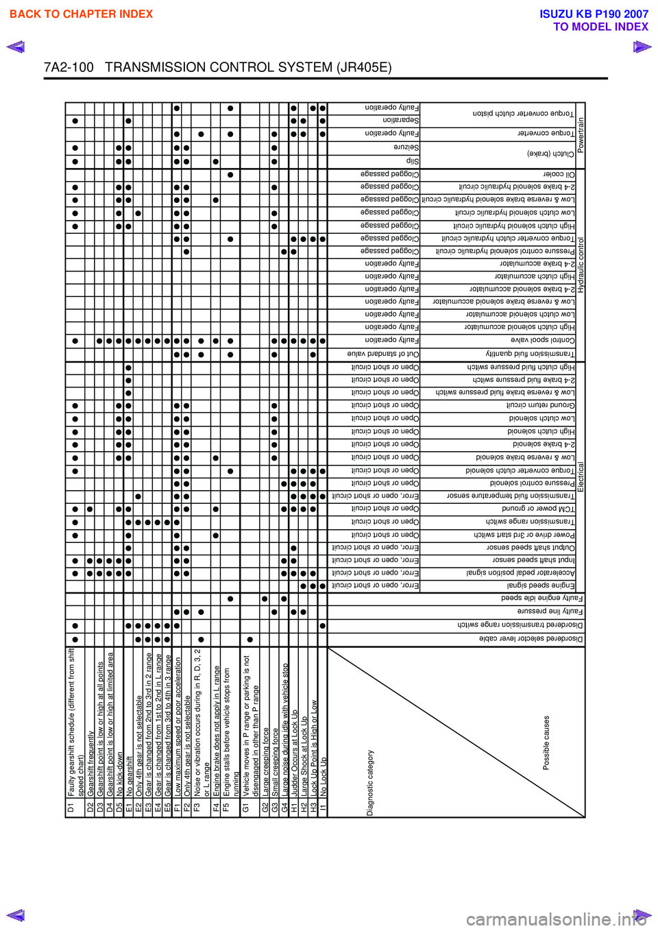
D1
Faulty gearshift schedule (different from shift
speed chart)
D2 Gearshift frequentlyD3Gearshift point is low or high at all pointsD4Gearshift point is low or high at limited areaD5No kick-downE1No gearshiftE2Only 4th gear is not selectableE3Gear is changed from 2nd to 3rd in 2 rangeE4Gear is changed from 1st to 2nd in L rangeE5Gear is changed from 3rd to 4th in 3 rangeF1Low maximum speed or poor accelerationF2Only 4th gear is not selectableF3
Noise or vibration occurs during in R, D, 3, 2
or L range
F4 Engine brake does not apply in L rangeF5
Engine stalls before vehicle stops from
running
G1
Vehicle moves in P range or parking is not
disengaged in other than P range
G2 Large creeping forceG3Small creeping forceG4Large noise during idle with vehicle stopH1Judder Occurs at Lock UpH2Large Shock at Lock UpH3Lock Up Point is High or LowI1No Lock Up
Error, open or short circuit
Error, open or short circuit
Error, open or short circuit
Error, open or short circuit
Open or short circuit
Open or short circuit
Open or short circuit
Error, open or short circuit
Open or short circuit
Open or short circuit
Open or short circuit
Open or short circuit
Open or short circuit
Open or short circuit
Open or short circuit
Open or short circuit
Open or short circuit
Open or short circuit
Out of standard value
Faulty operation
Faulty operation
Faulty operation
Faulty operation
Faulty operation
Faulty operation
Faulty operation
Clogged passage
Clogged passage
Clogged passage
Clogged passage
Clogged passage
Clogged passage
Clogged passage
Slip
Seizure
Faulty operation
Separation
Faulty operation
Engine speed signal
Accelerator pedal position signal
Input shaft speed sensor
Output shaft speed sensor
Power drive or 3rd start switch
Transmission range switch
TCM power or ground
Transmission fluid temperature sensor
Pressure control solenoid
Torque converter clutch solenoid
Low & reverse brake solenoid
2-4 brake solenoid
High clutch solenoid
Low clutch solenoid
Ground return circuit
Low & reverse brake fluid pressure switch
2-4 brake fluid pressure switch
High clutch fluid pressure switch
Transmission fluid quantity
Control spool valve
High clutch solenoid accumulator
Low clutch solenoid accumulator
Low & reverse brake solenoid accumulator
2-4 brake solenoid accumulator
High clutch accumulator
2-4 brake accumulator
Pressure control solenoid hydraulic circuit
Torque converter clutch hydraulic circuit
High clutch solenoid hydraulic circuit
Low clutch solenoid hydraulic circuit
Low & reverse brake solenoid hydraulic circuit
2-4 brake solenoid hydraulic circuit
Oil cooler
Torque converter
Diagnostic category
Possible causes
Electrical
Disordered selector lever cable
Disordered transmission range switch
Faulty line pressure
Faulty engine idle speed
Clutch (brake)
Torque converter clutch piston
Hydraulic control
Powertrain
BACK TO CHAPTER INDEX
TO MODEL INDEX
ISUZU KB P190 2007
Page 4385 of 6020
TRANSMISSION CONTROL SYSTEM (JR405E) 7A2-101
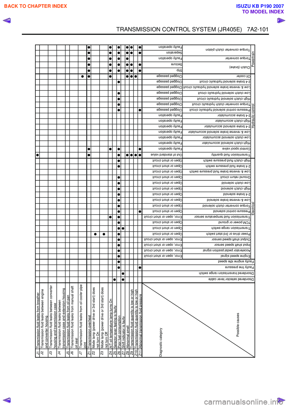
J1Transmission fluid leaks from breatherJ2
Transmission fluid leaks between engine
and converter housing
J3
Transmission fluid leaks between converter
housing and transmission case
J4
Transmission fluid leaks between
transmission case and extension housing
J5 Transmission fluid leaks from oil panJ6
Transmission fluid leaks from manual shaft
oil seal
J7
Transmission fluid leaks from oil cooler pipe
joint
Z1 Transmission overheatZ2
Mode lamp (power drive or 3rd start) does
not turn On
Z3
Mode lamp (power drive or 3rd start) does
not turn Off
Z4 A/T oil temperature lamp turns OnZ5Selector lever feeling is faultyZ6Poor fuel consumptionZ7Shift indicator is faultyZ8Abnormal smellZ9Transmission fluid quantity is low or highZ10 Transmission fluid quantity is low or highZ11Abnormal transmission fluid pressure
Error, open or short circuit
Error, open or short circuit
Error, open or short circuit
Error, open or short circuit
Open or short circuit
Open or short circuit
Open or short circuit
Error, open or short circuit
Open or short circuit
Open or short circuit
Open or short circuit
Open or short circuit
Open or short circuit
Open or short circuit
Open or short circuit
Open or short circuit
Open or short circuit
Open or short circuit
Out of standard value
Faulty operation
Faulty operation
Faulty operation
Faulty operation
Faulty operation
Faulty operation
Faulty operation
Clogged passage
Clogged passage
Clogged passage
Clogged passage
Clogged passage
Clogged passage
Clogged passage
Slip
Seizure
Faulty operation
Separation
Faulty operation
Engine speed signal
Accelerator pedal position signal
Input shaft speed sensor
Output shaft speed sensor
Power drive or 3rd start switch
Transmission range switch
TCM power or ground
Transmission fluid temperature sensor
Pressure control solenoid
Torque converter clutch solenoid
Low & reverse brake solenoid
2-4 brake solenoid
High clutch solenoid
Low clutch solenoid
Ground return circuit
Low & reverse brake fluid pressure switch
2-4 brake fluid pressure switch
High clutch fluid pressure switch
Transmission fluid quantity
Control spool valve
High clutch solenoid accumulator
Low clutch solenoid accumulator
Low & reverse brake solenoid accumulator
2-4 brake solenoid accumulator
High clutch accumulator
2-4 brake accumulator
Pressure control solenoid hydraulic circuit
Torque converter clutch hydraulic circuit
High clutch solenoid hydraulic circuit
Low clutch solenoid hydraulic circuit
Low & reverse brake solenoid hydraulic circuit
2-4 brake solenoid hydraulic circuit
Oil cooler
Torque converter
Clutch (brake)
Torque converter clutch piston
Hydraulic control
Powertrain
Diagnostic category
Possible causes
Electrical
Disordered selector lever cable
Disordered transmission range switch
Faulty line pressure
Faulty engine idle speed
BACK TO CHAPTER INDEX
TO MODEL INDEX
ISUZU KB P190 2007
Page 4396 of 6020
7A2-112 TRANSMISSION CONTROL SYSTEM (JR405E)
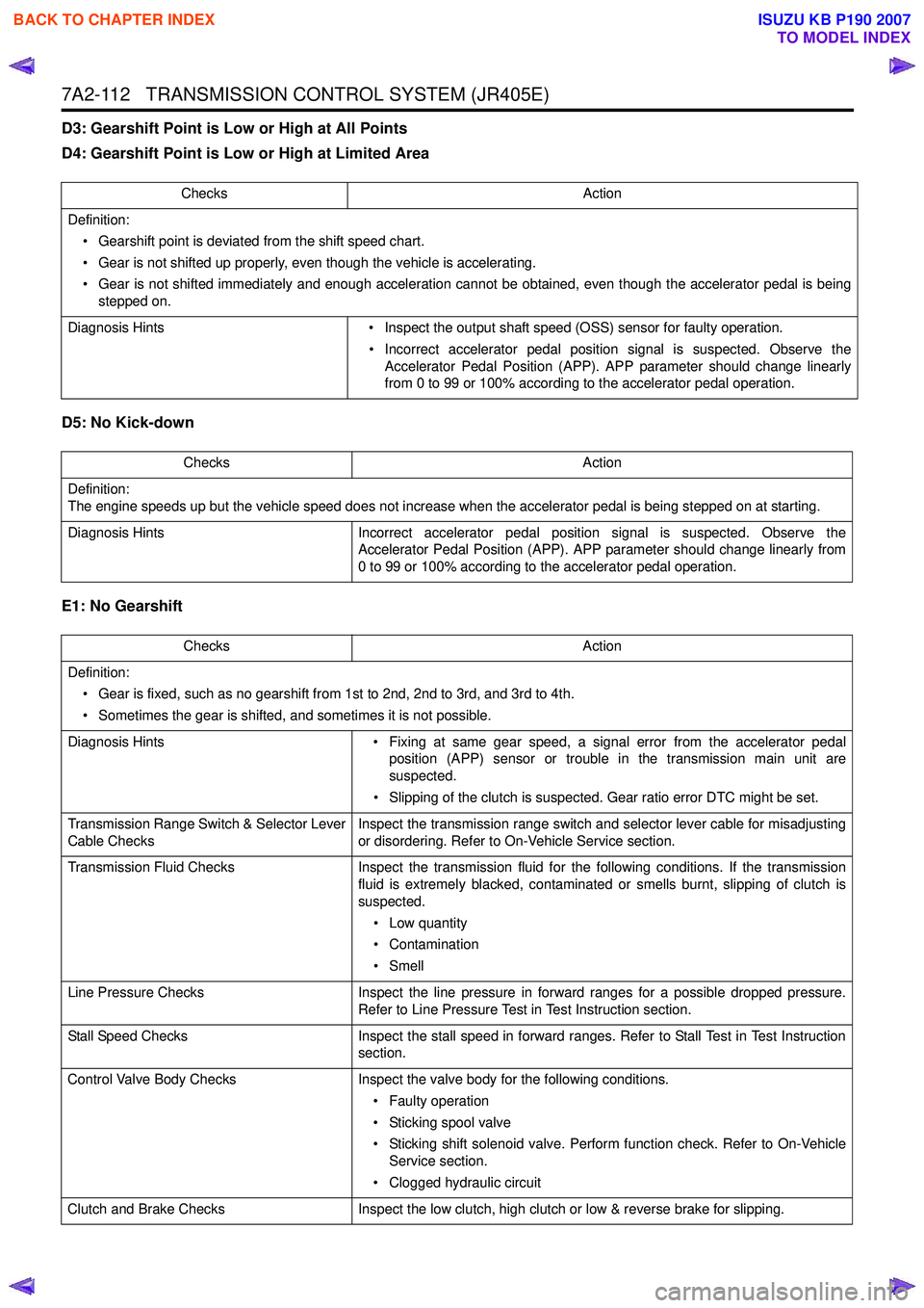
D3: Gearshift Point is Low or High at All Points
D4: Gearshift Point is Low or High at Limited Area
D5: No Kick-down
E1: No Gearshift
Checks Action
Definition: • Gearshift point is deviated from the shift speed chart.
• Gear is not shifted up properly, even though the vehicle is accelerating.
• Gear is not shifted immediately and enough acceleration cannot be obtained, even though the accelerator pedal is being stepped on.
Diagnosis Hints • Inspect the output shaft speed (OSS) sensor for faulty operation.
• Incorrect accelerator pedal position signal is suspected. Observe the Accelerator Pedal Position (APP). APP parameter should change linearly
from 0 to 99 or 100% according to the accelerator pedal operation.
Checks Action
Definition:
The engine speeds up but the vehicle speed does not increase when the accelerator pedal is being stepped on at starting.
Diagnosis Hints Incorrect accelerator pedal position signal is suspected. Observe the
Accelerator Pedal Position (APP). APP parameter should change linearly from
0 to 99 or 100% according to the accelerator pedal operation.
Checks Action
Definition: • Gear is fixed, such as no gearshift from 1st to 2nd, 2nd to 3rd, and 3rd to 4th.
• Sometimes the gear is shifted, and sometimes it is not possible.
Diagnosis Hints • Fixing at same gear speed, a signal error from the accelerator pedal
position (APP) sensor or trouble in the transmission main unit are
suspected.
• Slipping of the clutch is suspected. Gear ratio error DTC might be set.
Transmission Range Switch & Selector Lever
Cable Checks Inspect the transmission range switch and selector lever cable for misadjusting
or disordering. Refer to On-Vehicle Service section.
Transmission Fluid Checks Inspect the transmission fluid for the following conditions. If the transmission
fluid is extremely blacked, contaminated or smells burnt, slipping of clutch is
suspected.
• Low quantity
• Contamination
•Smell
Line Pressure Checks Inspect the line pressure in forward ranges for a possible dropped pressure.
Refer to Line Pressure Test in Test Instruction section.
Stall Speed Checks Inspect the stall speed in forward ranges. Refer to Stall Test in Test Instruction
section.
Control Valve Body Checks Inspect the valve body for the following conditions.
• Faulty operation
• Sticking spool valve
• Sticking shift solenoid valve. Perform function check. Refer to On-Vehicle Service section.
• Clogged hydraulic circuit
Clutch and Brake Checks Inspect the low clutch, high clutch or low & reverse brake for slipping.
BACK TO CHAPTER INDEX
TO MODEL INDEX
ISUZU KB P190 2007
Page 4397 of 6020
TRANSMISSION CONTROL SYSTEM (JR405E) 7A2-113
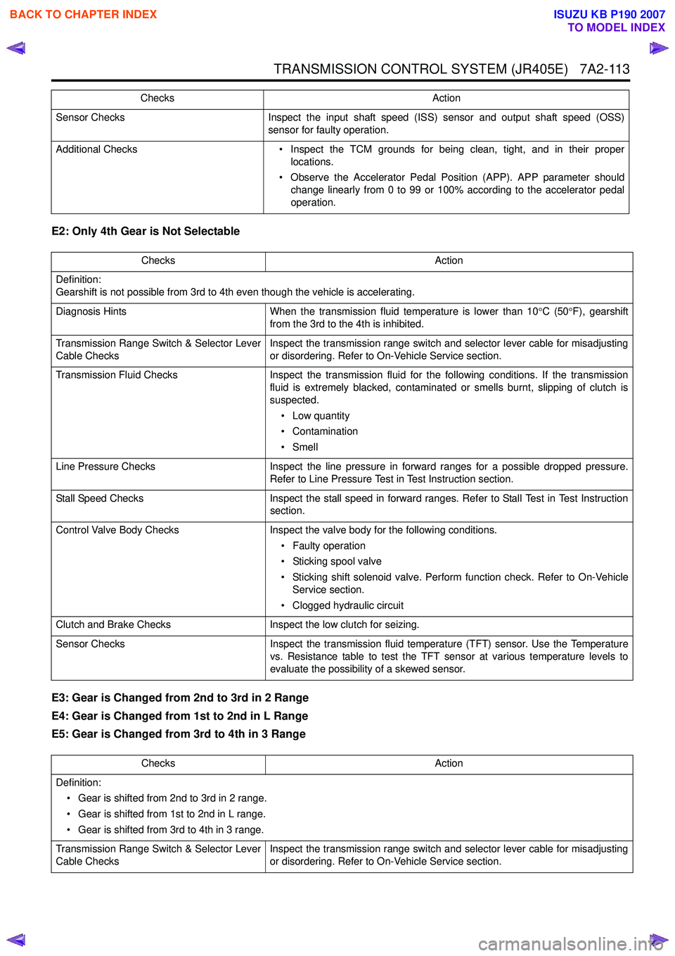
E2: Only 4th Gear is Not Selectable
E3: Gear is Changed from 2nd to 3rd in 2 Range
E4: Gear is Changed from 1st to 2nd in L Range
E5: Gear is Changed from 3rd to 4th in 3 Range
Sensor Checks Inspect the input shaft speed (ISS) sensor and output shaft speed (OSS)
sensor for faulty operation.
Additional Checks • Inspect the TCM grounds for being clean, tight, and in their proper
locations.
• Observe the Accelerator Pedal Position (APP). APP parameter should change linearly from 0 to 99 or 100% according to the accelerator pedal
operation.
Checks
Action
Checks Action
Definition:
Gearshift is not possible from 3rd to 4th even though the vehicle is accelerating.
Diagnosis Hints When the transmission fluid temperature is lower than 10 °C (50 °F), gearshift
from the 3rd to the 4th is inhibited.
Transmission Range Switch & Selector Lever
Cable Checks Inspect the transmission range switch and selector lever cable for misadjusting
or disordering. Refer to On-Vehicle Service section.
Transmission Fluid Checks Inspect the transmission fluid for the following conditions. If the transmission
fluid is extremely blacked, contaminated or smells burnt, slipping of clutch is
suspected.
• Low quantity
• Contamination
•Smell
Line Pressure Checks Inspect the line pressure in forward ranges for a possible dropped pressure.
Refer to Line Pressure Test in Test Instruction section.
Stall Speed Checks Inspect the stall speed in forward ranges. Refer to Stall Test in Test Instruction
section.
Control Valve Body Checks Inspect the valve body for the following conditions.
• Faulty operation
• Sticking spool valve
• Sticking shift solenoid valve. Perform function check. Refer to On-Vehicle Service section.
• Clogged hydraulic circuit
Clutch and Brake Checks Inspect the low clutch for seizing.
Sensor Checks Inspect the transmission fluid temperature (TFT) sensor. Use the Temperature
vs. Resistance table to test the TFT sensor at various temperature levels to
evaluate the possibility of a skewed sensor.
Checks Action
Definition: • Gear is shifted from 2nd to 3rd in 2 range.
• Gear is shifted from 1st to 2nd in L range.
• Gear is shifted from 3rd to 4th in 3 range.
Transmission Range Switch & Selector Lever
Cable Checks Inspect the transmission range switch and selector lever cable for misadjusting
or disordering. Refer to On-Vehicle Service section.
BACK TO CHAPTER INDEX
TO MODEL INDEX
ISUZU KB P190 2007
Page 4399 of 6020
TRANSMISSION CONTROL SYSTEM (JR405E) 7A2-115
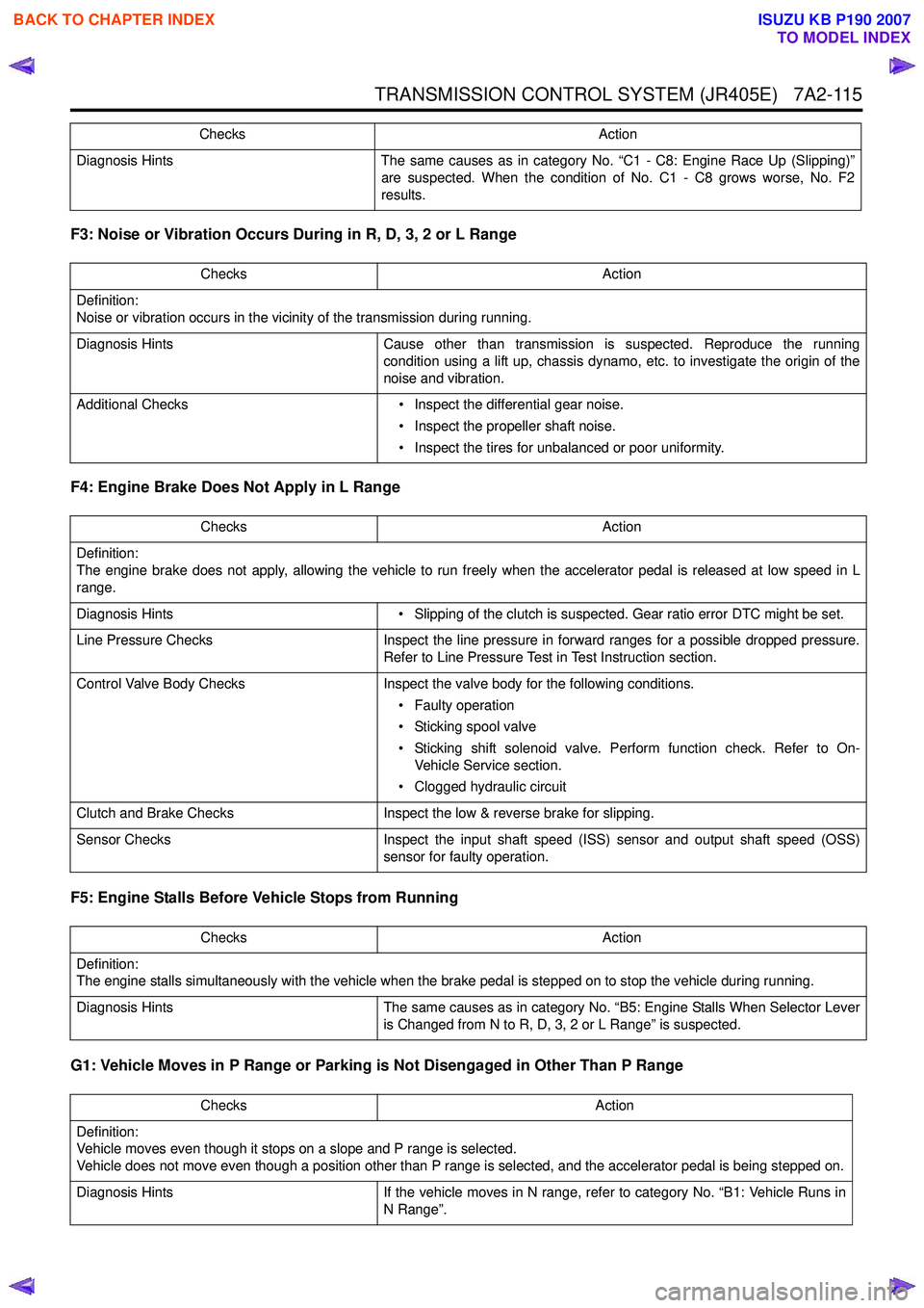
F3: Noise or Vibration Occurs During in R, D, 3, 2 or L Range
F4: Engine Brake Does Not Apply in L Range
F5: Engine Stalls Before Vehicle Stops from Running
G1: Vehicle Moves in P Range or Parking is Not Disengaged in Other Than P Range
Diagnosis Hints The same causes as in category No. “C1 - C8: Engine Race Up (Slipping)”
are suspected. When the condition of No. C1 - C8 grows worse, No. F2
results.
Checks Action
Definition:
Noise or vibration occurs in the vicinity of the transmission during running.
Diagnosis Hints Cause other than transmission is suspected. Reproduce the running
condition using a lift up, chassis dynamo, etc. to investigate the origin of the
noise and vibration.
Additional Checks • Inspect the differential gear noise.
• Inspect the propeller shaft noise.
• Inspect the tires for unbalanced or poor uniformity.
Checks
Action
Checks Action
Definition:
The engine brake does not apply, allowing the vehicle to run freely when the accelerator pedal is released at low speed in L
range.
Diagnosis Hints • Slipping of the clutch is suspected. Gear ratio error DTC might be set.
Line Pressure Checks Inspect the line pressure in forward ranges for a possible dropped pressure.
Refer to Line Pressure Test in Test Instruction section.
Control Valve Body Checks Inspect the valve body for the following conditions.
• Faulty operation
• Sticking spool valve
• Sticking shift solenoid valve. Perform function check. Refer to On- Vehicle Service section.
• Clogged hydraulic circuit
Clutch and Brake Checks Inspect the low & reverse brake for slipping.
Sensor Checks Inspect the input shaft speed (ISS) sensor and output shaft speed (OSS)
sensor for faulty operation.
Checks Action
Definition:
The engine stalls simultaneously with the vehicle when the brake pedal is stepped on to stop the vehicle during running.
Diagnosis Hints The same causes as in category No. “B5: Engine Stalls When Selector Lever
is Changed from N to R, D, 3, 2 or L Range” is suspected.
Checks Action
Definition:
Vehicle moves even though it stops on a slope and P range is selected.
Vehicle does not move even though a position other than P range is selected, and the accelerator pedal is being stepped on.
Diagnosis Hints If the vehicle moves in N range, refer to category No. “B1: Vehicle Runs in
N Range”.
BACK TO CHAPTER INDEX
TO MODEL INDEX
ISUZU KB P190 2007
Page 4406 of 6020
7A2-122 TRANSMISSION CONTROL SYSTEM (JR405E)
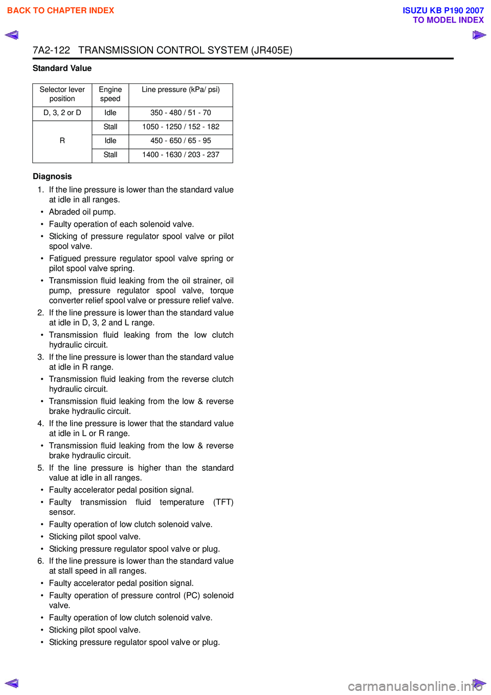
Standard Value
Diagnosis 1. If the line pressure is lower than the standard value at idle in all ranges.
• Abraded oil pump.
• Faulty operation of each solenoid valve.
• Sticking of pressure regulator spool valve or pilot spool valve.
• Fatigued pressure regulator spool valve spring or pilot spool valve spring.
• Transmission fluid leaking from the oil strainer, oil pump, pressure regulator spool valve, torque
converter relief spool valve or pressure relief valve.
2. If the line pressure is lower than the standard value at idle in D, 3, 2 and L range.
• Transmission fluid leaking from the low clutch hydraulic circuit.
3. If the line pressure is lower than the standard value at idle in R range.
• Transmission fluid leaking from the reverse clutch hydraulic circuit.
• Transmission fluid leaking from the low & reverse brake hydraulic circuit.
4. If the line pressure is lower that the standard value at idle in L or R range.
• Transmission fluid leaking from the low & reverse brake hydraulic circuit.
5. If the line pressure is higher than the standard value at idle in all ranges.
• Faulty accelerator pedal position signal.
• Faulty transmission fluid temperature (TFT) sensor.
• Faulty operation of low clutch solenoid valve.
• Sticking pilot spool valve.
• Sticking pressure regulator spool valve or plug.
6. If the line pressure is lower than the standard value at stall speed in all ranges.
• Faulty accelerator pedal position signal.
• Faulty operation of pressure control (PC) solenoid valve.
• Faulty operation of low clutch solenoid valve.
• Sticking pilot spool valve.
• Sticking pressure regulator spool valve or plug.
Selector lever position Engine
speed Line pressure (kPa/ psi)
D, 3, 2 or D Idle 350 - 480 / 51 - 70
R Stall 1050 - 1250 / 152 - 182
Idle 450 - 650 / 65 - 95
Stall 1400 - 1630 / 203 - 237
BACK TO CHAPTER INDEX
TO MODEL INDEX
ISUZU KB P190 2007
Page 4419 of 6020
TRANSMISSION CONTROL SYSTEM (JR405E) 7A2-135
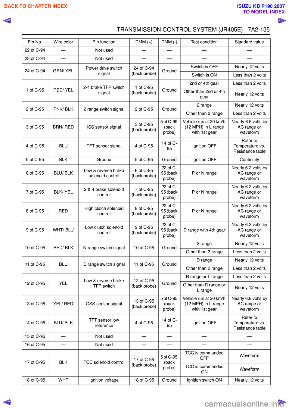
22 of C-94 —Not used— — ——
23 of C-94 — Not used— — ——
24 of C-94 GRN/ YEL Power drive switch
signal 24 of C-94
(back probe) GroundSwitch is OFF Nearly 12 volts
Switch is ON Less than 2 volts
1 of C-95 RED/ YEL 2-4 brake TFP switch
signal 1 of C-95
(back probe) Ground2nd or 4th gear Less than 2 volts
Other than 2nd or 4th gear Nearly 12 volts
2 of C-95 PNK/ BLK 2 range switch signal 2 of C-95 Ground 2 range
Nearly 12 volts
Other than 2 range Less than 2 volts
3 of C-95 BRN/ RED ISS sensor signal 3 of C-95
(back probe) 5 of C-95
(back
probe) Vehicle run at 20 km/h
(12 MPH) in L range with 1st gear Nearly 6.5 volts by
AC range or waveform
4 of C-95 BLU TFT sensor signal 4 of C-95 14 of C-
95 Ignition OFF Refer to
Temperature vs.
Resistance table
5 of C-95 BLK Ground5 of C-95 Ground Ignition OFF Continuity
6 of C-95 BLU/ BLK Low & reverse brake
solenoid control 6 of C-95
(back probe) 22 of C-
95 (back
probe) P or N range
Nearly 6.2 volts by
AC range or
waveform
7 of C-95 BLK/ YEL 2 & 4 brake solenoid
control 7 of C-95
(back probe) 22 of C-
95 (back
probe) P or N range
Nearly 6.2 volts by
AC range or
waveform
8 of C-95 RED High clutch solenoid
control 8 of C-95
(back probe) 22 of C-
95 (back
probe) P or N range
Nearly 6.2 volts by
AC range or
waveform
9 of C-95 WHT/ BLU Low clutch solenoid
control 9 of C-95
(back probe) 22 of C-
95 (back
probe) D range with 4th gear
Nearly 6.2 volts by
AC range or
waveform
10 of C-95 RED/ BLK N range switch signal 10 of C-95 Ground 2 range
Nearly 12 volts
Other than 2 range Less than 2 volts
11 of C-95 BLU D range switch signal 11 of C-95 Ground D range
Nearly 12 volts
Other than 2 range Less than 2 volts
12 of C-95 YEL Low & reverse brake
TFP switch 12 of C-95
(back probe) GroundR range or L range Less than 2 volts
Other than R range or L range Nearly 12 volts
13 of C-95 YEL/ RED OSS sensor signal 13 of C-95
(back probe) 5 of C-95
(back
probe) Vehicle run at 20 km/h
(12 MPH) in L range with 1st gear Nearly 6.8 volts by
AC range or waveform
14 of C-95 BLU/ BLK TFT sensor low
reference 4 of C-9514 of C-
95 Ignition OFF Refer to
Temperature vs.
Resistance table
15 of C-95 — Not used— — ——
16 of C-95 — Not used— — ——
17 of C-95 BLK TCC solenoid control 17 of C-95
(back probe) 5 of C-95
(back
probe) TCC is commanded
OFF Waveform
TCC is commanded ON Waveform
18 of C-95 WHT Ignition voltage 18 of C-95 Ground Ignition switch ON Nearly 12 volts Pin No. Wire color Pin function DMM (+) DMM (-) Test condition Standard value
BACK TO CHAPTER INDEX
TO MODEL INDEX
ISUZU KB P190 2007