2007 ISUZU KB P190 brake sensor
[x] Cancel search: brake sensorPage 1231 of 6020
Engine Control System (4JH1) 6E-197
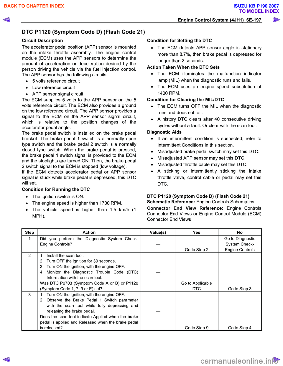
DTC P1120 (Symptom Code D) (Flash Code 21)
Circuit Description
The accelerator pedal position (APP) sensor is mounted
on the intake throttle assembly. The engine control
module (ECM) uses the APP sensors to determine the
amount of acceleration or deceleration desired by the
person driving the vehicle via the fuel injection control.
The APP sensor has the following circuits.
• 5 volts reference circuit
• Low reference circuit
• APP sensor signal circuit
The ECM supplies 5 volts to the APP sensor on the 5
volts reference circuit. The ECM also provides a ground
on the low reference circuit. The APP sensor provides a
signal to the ECM on the APP sensor signal circuit,
which is relative to the position changes of the
accelerator pedal angle.
The brake pedal switch is installed on the brake pedal
bracket. The brake pedal 1 switch is a normally open
type switch and the brake pedal 2 switch is a normally
closed type switch. W hen the brake pedal is pressed,
the brake pedal 1 switch signal is provided to the ECM
and the stoplights are turned ON. Then, the brake pedal
2 switch signal to the ECM is stopped (low voltage).
If the ECM detects accelerator pedal or APP senso
r
signal is stuck while brake pedal is depressed, this DTC
will set.
Condition for Running the DTC
• The ignition switch is ON.
• The engine speed is higher than 1700 RPM.
• The vehicle speed is higher than 1.5 km/h (1
MPH).
Condition for Setting the DTC
• The ECM detects APP sensor angle is stationar
y
more than 8.7%, then brake pedal is depressed fo
r
longer than 2 seconds.
Action Taken When the DTC Sets • The ECM illuminates the malfunction indicato
r
lamp (MIL) when the diagnostic runs and fails.
• The ECM uses an engine speed substitution o
f
1400 RPM.
Condition for Clearing the MIL/DTC • The ECM turns OFF the MIL when the diagnostic
runs and does not fail.
• A history DTC clears after 40 consecutive driving
cycles without a fault. Or clear with the scan tool.
Diagnostic Aids • If an intermittent condition is suspected, refer to
Intermittent Conditions in this section.
• Misadjusted brake pedal switch may set this DTC.
• Misadjusted APP sensor may set this DTC.
• Misadjusted throttle cable may set this DTC.
• A sticking or intermittently sticking the intake
throttle valve, control cable or pedal may set this
DTC.
DTC P1120 (Symptom Code D) (Flash Code 21)
Schematic Reference: Engine Controls Schematics
Connector End View Reference: Engine Controls
Connector End Views or Engine Control Module (ECM)
Connector End Views
Step Action Value(s) Yes No
1 Did you perform the Diagnostic System Check-
Engine Controls?
Go to Step 2 Go to Diagnostic
System Check-
Engine Controls
2 1. Install the scan tool. 2. Turn OFF the ignition for 30 seconds.
3. Turn ON the ignition, with the engine OFF.
4. Monitor the Diagnostic Trouble Code (DTC) Information with the scan tool.
W as DTC P0703 (Symptom Code A or B) or P1120
(Symptom Code 1, 7, 9 or E) set?
Go to Applicable DTC Go to Step 3
3 1. Turn ON the ignition, with the engine OFF. 2. Observe the Brake Pedal 1 Switch parameter with the scan tool while fully depressing and
releasing the brake pedal.
Does the scan tool indicate Applied when the brake
pedal is applied and Released when the brake pedal
is released?
Go to Step 9 Go to Step 4
BACK TO CHAPTER INDEX
TO MODEL INDEX
ISUZU KB P190 2007
Page 1232 of 6020
6E-198 Engine Control System (4JH1)
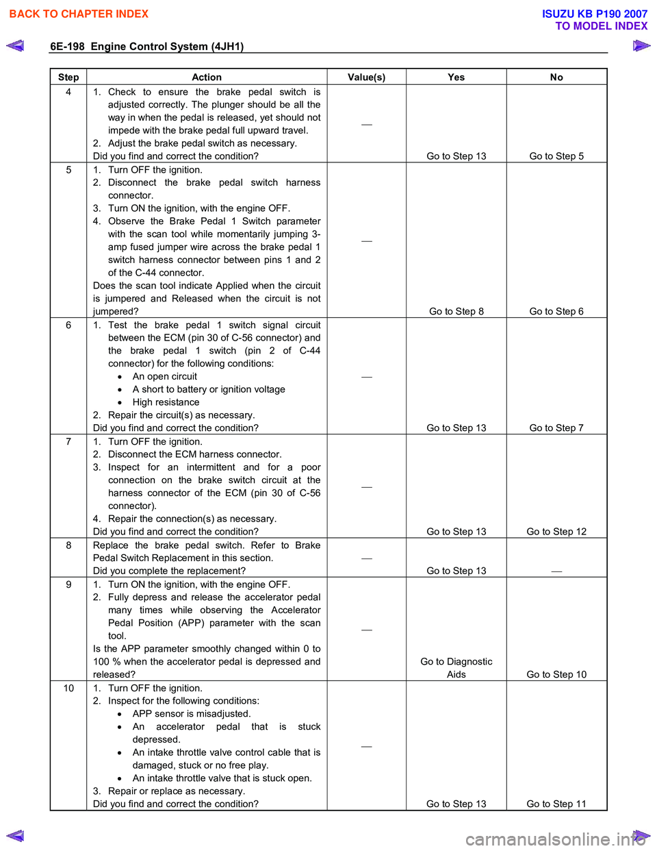
Step Action Value(s) Yes No
4 1. Check to ensure the brake pedal switch is
adjusted correctly. The plunger should be all the
way in when the pedal is released, yet should not
impede with the brake pedal full upward travel.
2. Adjust the brake pedal switch as necessary.
Did you find and correct the condition?
Go to Step 13 Go to Step 5
5 1. Turn OFF the ignition. 2. Disconnect the brake pedal switch harness connector.
3. Turn ON the ignition, with the engine OFF.
4. Observe the Brake Pedal 1 Switch parameter with the scan tool while momentarily jumping 3-
amp fused jumper wire across the brake pedal 1
switch harness connector between pins 1 and 2
of the C-44 connector.
Does the scan tool indicate Applied when the circuit
is jumpered and Released when the circuit is not
jumpered?
Go to Step 8 Go to Step 6
6 1. Test the brake pedal 1 switch signal circuit between the ECM (pin 30 of C-56 connector) and
the brake pedal 1 switch (pin 2 of C-44
connector) for the following conditions: • An open circuit
• A short to battery or ignition voltage
• High resistance
2. Repair the circuit(s) as necessary.
Did you find and correct the condition?
Go to Step 13 Go to Step 7
7 1. Turn OFF the ignition. 2. Disconnect the ECM harness connector.
3. Inspect for an intermittent and for a poor connection on the brake switch circuit at the
harness connector of the ECM (pin 30 of C-56
connector).
4. Repair the connection(s) as necessary.
Did you find and correct the condition?
Go to Step 13 Go to Step 12
8 Replace the brake pedal switch. Refer to Brake Pedal Switch Replacement in this section.
Did you complete the replacement?
Go to Step 13
9 1. Turn ON the ignition, with the engine OFF.
2. Fully depress and release the accelerator pedal many times while observing the Accelerator
Pedal Position (APP) parameter with the scan
tool.
Is the APP parameter smoothly changed within 0 to
100 % when the accelerator pedal is depressed and
released?
Go to Diagnostic Aids Go to Step 10
10 1. Turn OFF the ignition. 2. Inspect for the following conditions: • APP sensor is misadjusted.
• An accelerator pedal that is stuck
depressed.
• An intake throttle valve control cable that is
damaged, stuck or no free play.
• An intake throttle valve that is stuck open.
3. Repair or replace as necessary.
Did you find and correct the condition?
Go to Step 13 Go to Step 11
BACK TO CHAPTER INDEX
TO MODEL INDEX
ISUZU KB P190 2007
Page 1233 of 6020
Engine Control System (4JH1) 6E-199
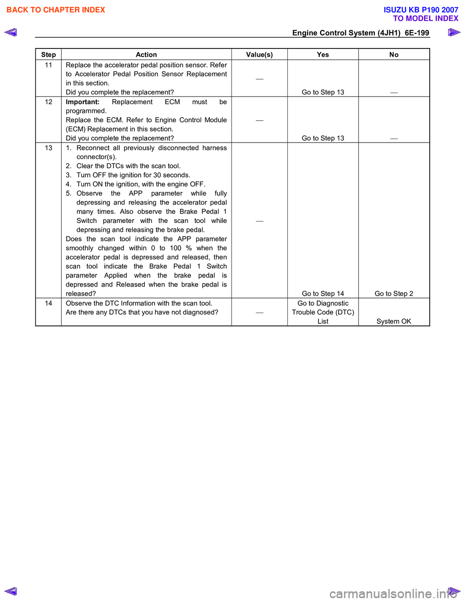
Step Action Value(s) Yes No
11 Replace the accelerator pedal position sensor. Refer
to Accelerator Pedal Position Sensor Replacement
in this section.
Did you complete the replacement?
Go to Step 13
12 Important: Replacement ECM must be
programmed.
Replace the ECM. Refer to Engine Control Module
(ECM) Replacement in this section.
Did you complete the replacement?
Go to Step 13
13 1. Reconnect all previously disconnected harness
connector(s).
2. Clear the DTCs with the scan tool.
3. Turn OFF the ignition for 30 seconds.
4. Turn ON the ignition, with the engine OFF.
5. Observe the APP parameter while fully depressing and releasing the accelerator pedal
many times. Also observe the Brake Pedal 1
Switch parameter with the scan tool while
depressing and releasing the brake pedal.
Does the scan tool indicate the APP parameter
smoothly changed within 0 to 100 % when the
accelerator pedal is depressed and released, then
scan tool indicate the Brake Pedal 1 Switch
parameter Applied when the brake pedal is
depressed and Released when the brake pedal is
released?
Go to Step 14 Go to Step 2
14 Observe the DTC Information with the scan tool. Are there any DTCs that you have not diagnosed? Go to Diagnostic
Trouble Code (DTC) List System OK
BACK TO CHAPTER INDEX
TO MODEL INDEX
ISUZU KB P190 2007
Page 1300 of 6020
6E-266 Engine Control System (4JH1)
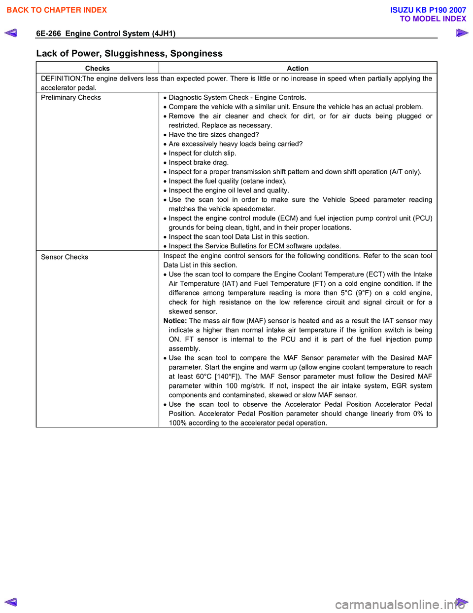
Lack of Power, Sluggishness, Sponginess
Checks Action
DEFINITION:The engine delivers less than expected power. There is little or no increase in speed when partially applying the
accelerator pedal.
Preliminary Checks • Diagnostic System Check - Engine Controls.
• Compare the vehicle with a similar unit. Ensure the vehicle has an actual problem.
• Remove the air cleaner and check for dirt, or for air ducts being plugged or
restricted. Replace as necessary.
• Have the tire sizes changed?
• Are excessively heavy loads being carried?
• Inspect for clutch slip.
• Inspect brake drag.
• Inspect for a proper transmission shift pattern and down shift operation (A/T only).
• Inspect the fuel quality (cetane index).
• Inspect the engine oil level and quality.
• Use the scan tool in order to make sure the Vehicle Speed parameter reading
matches the vehicle speedometer.
• Inspect the engine control module (ECM) and fuel injection pump control unit (PCU)
grounds for being clean, tight, and in their proper locations.
• Inspect the scan tool Data List in this section.
• Inspect the Service Bulletins for ECM software updates.
Sensor Checks Inspect the engine control sensors for the following conditions. Refer to the scan tool
Data List in this section.
• Use the scan tool to compare the Engine Coolant Temperature (ECT) with the Intake
Air Temperature (IAT) and Fuel Temperature (FT) on a cold engine condition. If the
difference among temperature reading is more than 5°C (9°F) on a cold engine,
check for high resistance on the low reference circuit and signal circuit or for a
skewed sensor.
Notice: The mass air flow (MAF) sensor is heated and as a result the IAT sensor may
indicate a higher than normal intake air temperature if the ignition switch is being
ON. FT sensor is internal to the PCU and it is part of the fuel injection pump
assembly.
• Use the scan tool to compare the MAF Sensor parameter with the Desired MAF
parameter. Start the engine and warm up (allow engine coolant temperature to reach
at least 60°C [140°F]). The MAF Sensor parameter must follow the Desired MAF
parameter within 100 mg/strk. If not, inspect the air intake system, EGR system
components and contaminated, skewed or slow MAF sensor.
• Use the scan tool to observe the Accelerator Pedal Position Accelerator Pedal
Position. Accelerator Pedal Position parameter should change linearly from 0% to
100% according to the accelerator pedal operation.
BACK TO CHAPTER INDEX
TO MODEL INDEX
ISUZU KB P190 2007
Page 1305 of 6020
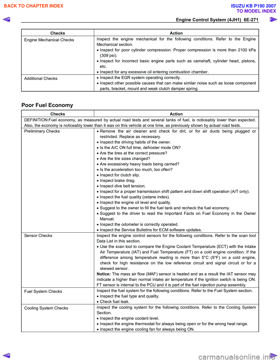
Engine Control System (4JH1) 6E-271
Checks Action
Engine Mechanical Checks Inspect the engine mechanical for the following conditions. Refer to the Engine
Mechanical section.
• Inspect for poor cylinder compression. Proper compression is more than 2100 kPa
(309 psi).
• Inspect for incorrect basic engine parts such as camshaft, cylinder head, pistons,
etc.
• Inspect for any excessive oil entering combustion chamber.
Additional Checks •
Inspect the EGR system operating correctly.
• Inspect other possible causes that can make similar noise such as loose component
parts, bracket, mount and weak clutch damper spring.
Poor Fuel Economy
Checks Action
DEFINITION:Fuel economy, as measured by actual road tests and several tanks of fuel, is noticeably lower than expected.
Also, the economy is noticeably lower than it was on this vehicle at one time, as previously shown by actual road tests.
Preliminary Checks • Remove the air cleaner and check for dirt, or for air ducts being plugged or
restricted. Replace as necessary.
• Inspect the driving habits of the owner.
• Is the A/C ON full time, defroster mode ON?
• Are the tires at the correct pressure?
• Are the tire sizes changed?
• Are excessively heavy loads being carried?
• Is the acceleration too much, too often?
• Inspect for clutch slip.
• Inspect brake drag.
• Inspect dive belt tension.
• Inspect for a proper transmission shift pattern and down shift operation (A/T only).
• Inspect the fuel quality (cetane index).
• Inspect the engine oil level and quality.
• Suggest to the owner to fill the fuel tank and recheck the fuel economy.
• Suggest to the driver to read the Important Facts on Fuel Economy in the Owner
Manual.
• Inspect the odometer is correctly operated.
• Inspect the Service Bulletins for ECM software updates.
Sensor Checks Inspect the engine control sensors for the following conditions. Refer to the scan tool
Data List in this section.
• Use the scan tool to compare the Engine Coolant Temperature (ECT) with the Intake
Air Temperature (IAT) and Fuel Temperature (FT) on a cold engine condition. If the
difference among temperature reading is more than 5°C (9°F) on a cold engine,
check for high resistance on the low reference circuit and signal circuit or for a
skewed sensor.
Notice: The mass air flow (MAF) sensor is heated and as a result the IAT sensor may
indicate a higher than normal intake air temperature if the ignition switch is being ON.
FT sensor is internal to the PCU and it is part of the fuel injection pump assembly.
Fuel System Checks Inspect the fuel system for the following conditions. Refer to the Fuel System section.
• Inspect the fuel type and quality.
• Check fuel leak.
Cooling System Checks Inspect the cooling system for the following conditions. Refer to the Cooling System
Section.
• Inspect the engine coolant level.
• Inspect the engine thermostat for always being open or for the wrong heat range.
• Inspect the engine cooling fan for always being ON.
BACK TO CHAPTER INDEX
TO MODEL INDEX
ISUZU KB P190 2007
Page 1623 of 6020
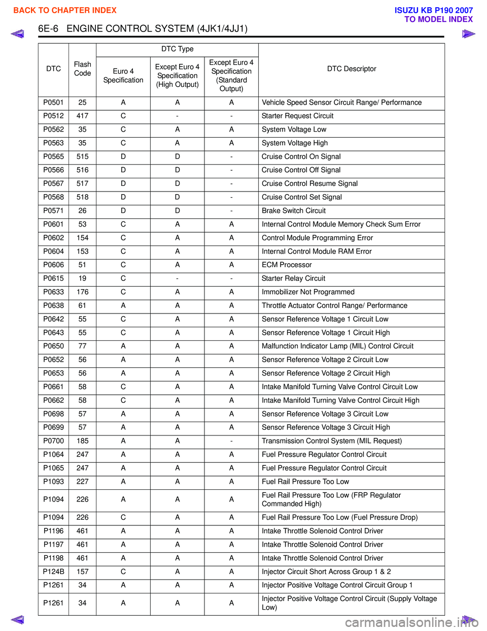
6E-6 ENGINE CONTROL SYSTEM (4JK1/4JJ1)
P0501 25 AAA Vehicle Speed Sensor Circuit Range/ Performance
P0512 417 C -- Starter Request Circuit
P0562 35 C AA System Voltage Low
P0563 35 C AA System Voltage High
P0565 515 D D- Cruise Control On Signal
P0566 516 D D- Cruise Control Off Signal
P0567 517 D D- Cruise Control Resume Signal
P0568 518 D D- Cruise Control Set Signal
P0571 26 D D- Brake Switch Circuit
P0601 53 C AA Internal Control Module Memory Check Sum Error
P0602 154 C AA Control Module Programming Error
P0604 153 C AA Internal Control Module RAM Error
P0606 51 C AA ECM Processor
P0615 19 C -- Starter Relay Circuit
P0633 176 C AA Immobilizer Not Programmed
P0638 61 A AA Throttle Actuator Control Range/ Performance
P0642 55 C AA Sensor Reference Voltage 1 Circuit Low
P0643 55 C AA Sensor Reference Voltage 1 Circuit High
P0650 77 A AA Malfunction Indicator Lamp (MIL) Control Circuit
P0652 56 A AA Sensor Reference Voltage 2 Circuit Low
P0653 56 A AA Sensor Reference Voltage 2 Circuit High
P0661 58 C AA Intake Manifold Turning Valve Control Circuit Low
P0662 58 C AA Intake Manifold Turning Valve Control Circuit High
P0698 57 A AA Sensor Reference Voltage 3 Circuit Low
P0699 57 A AA Sensor Reference Voltage 3 Circuit High
P0700 185 A A- Transmission Control System (MIL Request)
P1064 247 A AA Fuel Pressure Regulator Control Circuit
P1065 247 A AA Fuel Pressure Regulator Control Circuit
P1093 227 A AA Fuel Rail Pressure Too Low
P1094 226 A AAFuel Rail Pressure Too Low (FRP Regulator
Commanded High)
P1094 226 C AA Fuel Rail Pressure Too Low (Fuel Pressure Drop)
P1196 461 A AA Intake Throttle Solenoid Control Driver
P1197 461 A AA Intake Throttle Solenoid Control Driver
P1198 461 A AA Intake Throttle Solenoid Control Driver
P124B 157 C AA Injector Circuit Short Across Group 1 & 2
P1261 34 A AA Injector Positive Voltage Control Circuit Group 1
P1261 34 A AAInjector Positive Voltage Control Circuit (Supply Voltage
Low)
DTC
Flash
Code DTC Type
DTC Descriptor
Euro 4
Specification Except Euro 4
Specification
(High Output) Except Euro 4
Specification (Standard Output)
BACK TO CHAPTER INDEX
TO MODEL INDEX
ISUZU KB P190 2007
Page 1649 of 6020
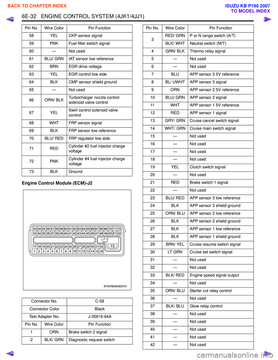
6E-32 ENGINE CONTROL SYSTEM (4JK1/4JJ1)
Engine Control Module (ECM)-J2
Pin No. Wire ColorPin Function
58 YEL CKP sensor signal
59 PNK Fuel filter switch signal
60 — Not used
61 BLU/ GRN IAT sensor low reference
62 BRN EGR drive voltage
63 YEL EGR control low side
64 BLK CMP sensor shield ground
65 — Not used
66 ORN/ BLK Turbocharger nozzle control
solenoid valve control
67 YEL Swirl control solenoid valve
control
68 WHT FRP sensor signal
69 BLK FRP sensor low reference
70 BLU/ RED FRP regulator low side
71 RED Cylinder #2 fuel injector charge
voltage
72 PNK Cylinder #4 fuel injector charge
voltage
73 BLK Ground
Connector No. C-58
Connector Color Black
Test Adapter No. J-35616-64A
Pin No. Wire Color Pin Function
1 ORN Brake switch 2 signal
2 BLK/ GRN Diagnostic request switch
RTW76ESH003101
12345678910111213141516
17 18 19 20 21 22 23 24 25 26 27 28 29 30 31 32
33 34 35 36 37 38 39 40 41 42 43 44 45 46 47 48 49 50 51 52
53 54 55 56 57 58 59 60 61 62 63 64 65 66 67 68 69 70 71 72
Pin No. Wire Color
Pin Function
3 RED/ GRN P or N range switch (A/T)
BLK/ WHT Neutral switch (M/T)
4 GRN/ BLK Thermo relay signal
5 — Not used
6 — Not used
7 BLU APP sensor 3 5V reference
8 BL/ UWHT APP sensor 3 signal
9 ORN APP sensor 2 5V reference
10 BLU/ GRN APP sensor 2 signal 11 WHT APP sensor 1 5V reference
12 RED APP sensor 1 signal
13 GRY/ GRN Cruise cancel switch signal
14 WHT/ GRN Cruise main switch signal
15 — Not used
16 — Not used
17 — Not used
18 — Not used
19 YEL Clutch switch signal
20 — Not used
21 RED Brake switch 1 signal
22 — Not used
23 BLU/ RED APP sensor 3 low reference
24 BLK APP sensor 3 shield ground
25 ORN/ BLU APP sensor 2 low reference
26 BLK APP sensor 2 shield ground
27 BLK APP sensor 1 low reference
28 BLK APP sensor 1 shield ground
29 BRN/ YEL Cruise resume switch signal
30 LT GRN Cruise set switch signal
31 — Not used
32 — Not used
33 BLK/ RED Engine speed signal output
34 — Not used
35 ORN/ BLU Starter cut relay control
36 — Not used
37 BLK/ BLU Glow relay control
38 — Not used
39 — Not used
40 — Not used
41 — Not used
42 — Not used
BACK TO CHAPTER INDEX
TO MODEL INDEX
ISUZU KB P190 2007
Page 1652 of 6020
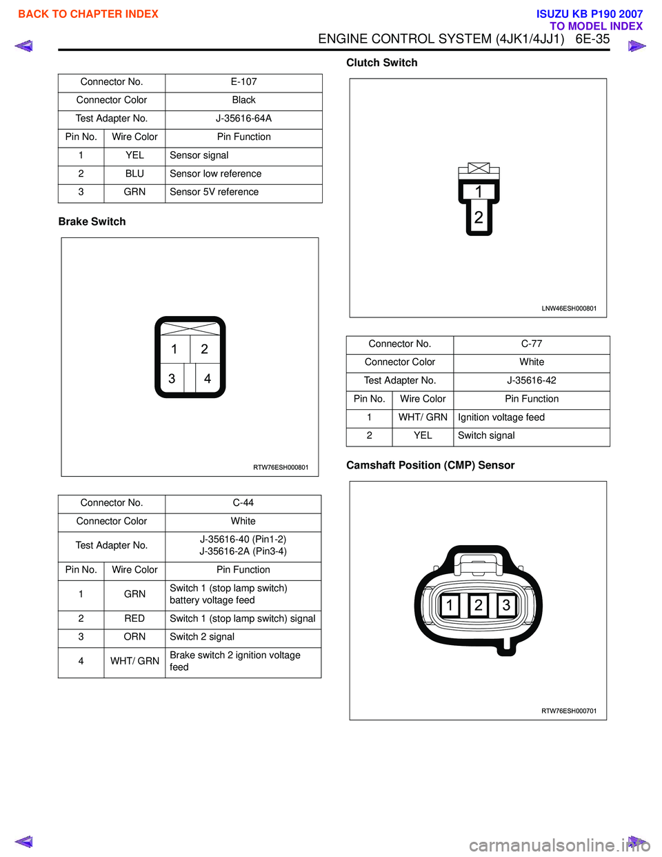
ENGINE CONTROL SYSTEM (4JK1/4JJ1) 6E-35
Brake SwitchClutch Switch
Camshaft Position (CMP) Sensor
Connector No.
E-107
Connector Color Black
Test Adapter No. J-35616-64A
Pin No. Wire Color Pin Function
1 YEL Sensor signal
2 BLU Sensor low reference
3 GRN Sensor 5V reference
Connector No. C-44
Connector Color White
Test Adapter No. J-35616-40 (Pin1-2)
J-35616-2A (Pin3-4)
Pin No. Wire Color Pin Function
1GRN Switch 1 (stop lamp switch)
battery voltage feed
2 RED Switch 1 (stop lamp switch) signal
3 ORN Switch 2 signal
4WHT/ GRN Brake switch 2 ignition voltage
feed
RTW76ESH000801
12
34Connector No. C-77
Connector Color White
Test Adapter No. J-35616-42
Pin No. Wire Color Pin Function
1 WHT/ GRN Ignition voltage feed
2 YEL Switch signal
LNW46ESH000801
1
2
RTW76ESH000701
123
BACK TO CHAPTER INDEX
TO MODEL INDEX
ISUZU KB P190 2007