2007 ISUZU KB P190 ignition
[x] Cancel search: ignitionPage 3576 of 6020
Engine Management – V6 – Service Operations Page 6C1-3–52
Oil Fouled (3)
W et, oily deposits with minor electrode wear possibly due to oil leaking past worn piston rings.
Breaking in a new or recently overhauled engine before the rings are fully seated may also result in this condition.
Deposit Fouling A (4)
Red brown, yellow and white coloured coatings on the insulator tip which are by-products of combustion. They come
from fuel and lubricating oil which generally contain additives. Most powdery deposits have no adverse effect on spark
plug operation, however, they may cause intermittent missing under severe operating conditions.
Deposit Fouling B (5)
Deposits similar to those identified in deposit fouling A (4). These are also by-products of combustion from fuel and
lubricating oil. Excessive valve stem clearances and / or defective intake valve seals allow too much oil to enter the
combustion chamber. The deposits will accumulate on the portion of the spark plug that projects into the chamber and
will be heaviest on the side facing the intake valve. If this condition is only detected in one or two cylinders, check the
valve stem seals.
Deposit Fouling C (6)
Most powdery deposits identified in deposit fouling A (4) have no adverse effect on the operation of the spark plug as
long as they remain powdery.
Under certain conditions of operation however, these deposits melt and form a shiny glaze coating on the insulator.
W hen hot, this acts as a good electrical conductor allowing the current to flow along the deposit instead of sparking
across the gap.
Detonation (7)
Commonly referred to as engine knock or pinging, detonation causes severe shocks inside the combustion chamber
causing damage to parts.
Pre-ignition (8)
Burnt or blistered insulator tip and badly eroded electrodes probably due to the excessive heat.
This is often caused by a cooling system blockage, sticking valves, improperly installed spark plugs or plugs that are the
wrong heat rating (too hot).
Sustained high speed with a heavy load can produce temperatures high enough to cause pre-ignition.
Heat Shock Failure (9)
A rapid increase in spark plug tip temperature under severe operating conditions can cause heat shock and result in
fractured insulators. This is a common cause of broken and cracked insulator tips.
Insufficient Installation Torque (10)
Poor contact between the spark plug and the cylinder head seat.
The lack of proper heat transfer that results from poor seat contact causes overheating of the spark plug. In many cases,
severe damage occurs. Dirty threads in the cylinder head can cause the plug to seize before it is seated.
Ensure the cylinder head and spark plug threads are free of deposits, burrs and scale before installation.
BACK TO CHAPTER INDEX
TO MODEL INDEX
ISUZU KB P190 2007
Page 3577 of 6020
Engine Management – V6 – Service Operations Page 6C1-3–53
Reinstall
Reinstallation of the spark plug is the reverse of the removal procedure, noting the following:
• Discard the spark plug if it has been
dropped.
• Do not use anti-seize compound or similar
lubricant on the spark plug threads.
1 Using a suitably sized rubber tube attached to the spark plug terminal post, hand start each spark plug into the cylinder head thread.
Failure to tighten a spark plug to the correct
torque specification may result in premature
spark plug failure, and / or engine damage.
2 Tighten the spark plug/s to the correct torque specification. Spark plug torque specification ...............16.0 – 20.0 Nm
3 Road test the vehicle and check for correct operation.
2.23 Throttle Body Assembly
Handling Precautions
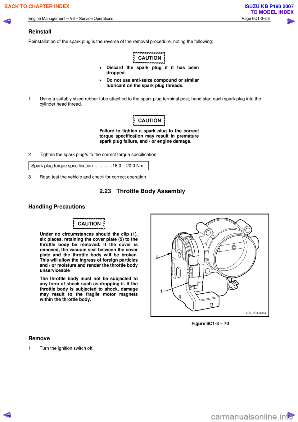
Under no circumstances should the clip (1),
six places, retaining the cover plate (2) to the
throttle body be removed. If the cover is
removed, the vacuum seal between the cover
plate and the throttle body will be broken.
This will allow the ingress of foreign particles
and / or moisture and render the throttle body
unserviceable
The throttle body must not be subjected to
any form of shock such as dropping it. If the
throttle body is subjected to shock, damage
may result to the fragile motor magnets
within the throttle body.
Figure 6C1-3 – 70
Remove
1 Turn the ignition switch off.
BACK TO CHAPTER INDEX
TO MODEL INDEX
ISUZU KB P190 2007
Page 3579 of 6020
Engine Management – V6 – Service Operations Page 6C1-3–55
Inspect
The following throttle body inspection procedure may be carried out with the throttle body installed on the vehicle. Prior to
performing a throttle body on-vehicle inspection:
• Turn the ignition switch off.
• Disconnect the throttle body wiring harness connector. Refer to Remove in this Section.
• Remove the air intake duct, refer to 2.16 Intake Air Duct Assembly.
To avoid serious personal injury, never
attempt to rotate the throttle plate manually
whilst the throttle body harness connector is
connected to the throttle body.
1 Fully open the throttle plate by hand and inspect the throttle body bore and throttle plate for any deposits.
When cleaning / inspecting the throttle body:
• Do not subject the throttle body assembly
to an immersion cleaner or a strong
solvent. Damage to the throttle position
sensor and / or sealed throttle shaft
bearings will result.
• Never use a wire brush or scraper to clean
the throttle body. A wire brush or sharp
tool may damage the throttle body
components.
2 Use a clean shop towel and a spray type hydro-carbon cleaner to clean the throttle body bore and throttle plate. If necessary, use a parts cleaning brush to remove heavy deposits.
3 Inspect the throttle body for a binding throttle plate by fully opening and closing the throttle plate by hand. It should open and close smoothly.
4 Inspect the throttle body for a bent or damaged throttle plate, cracks, corrosion, or distortion in the throttle body housing.
NOTE
The throttle body contains no serviceable parts
and should not be disassembled. If the throttle
body is damaged it must be replaced as an
assembly.
5 If the throttle body is affected by any of the above conditions, it must be replaced.
6 If an on-vehicle throttle body inspection was performed, perform the following:
• Reinstall the air intake duct, refer to 2.16 Intake Air Duct Assembly.
• Reconnect the throttle body wiring harness connector, refer to Reinstall in this Section.
• Road test the vehicle and check for correct operation, taking particular note that no air leaks are evident.
Reinstall
Reinstallation of the throttle body assembly is the reverse of the removal procedure, noting the following:
1 Ensure the throttle body and upper intake manifold mating surfaces are clean and free of foreign material.
2 Install a new throttle body to upper intake manifold gasket.
BACK TO CHAPTER INDEX
TO MODEL INDEX
ISUZU KB P190 2007
Page 3584 of 6020
Engine Management – V6 – Service Operations Page 6C1-3–60
4 Assembly Lubricants
Camshaft Position (CMP) Sensor O-ring ........................................... Engine Oil
Crankshaft Position (CKP) Sensor .................................................... Engine Oil
Evaporative Emission (EVAP) Canister Purge Valve
Quick Connect Fitting ........................................................................ Engine Oil
Fuel Feed Hose Quick Connect Fitting .............................................. Engine Oil
Fuel Injector Seals............................................................................. Engine Oil
Heated Oxygen Sensor (HO2S) – All .............................. Anti-seize Compound
Ignition Coil Boot .......................................................................Talcum Powder
Ignition Coil Sealing Rubber .............................................................. Engine Oil
BACK TO CHAPTER INDEX
TO MODEL INDEX
ISUZU KB P190 2007
Page 3585 of 6020
Engine Management – V6 – Service Operations Page 6C1-3–61
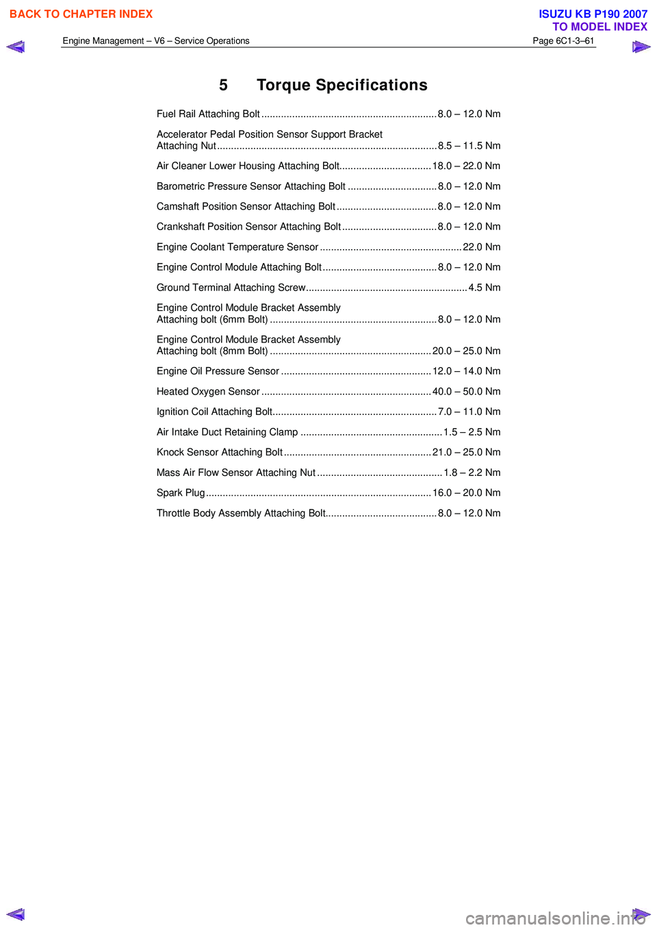
5 Torque Specifications
Fuel Rail Attaching Bolt ............................................................... 8.0 – 12.0 Nm
Accelerator Pedal Position Sensor Support Bracket
Attaching Nut ............................................................................... 8.5 – 11.5 Nm
Air Cleaner Lower Housing Attaching Bolt................................. 18.0 – 22.0 Nm
Barometric Pressure Sensor Attaching Bolt ................................ 8.0 – 12.0 Nm
Camshaft Position Sensor Attaching Bolt .................................... 8.0 – 12.0 Nm
Crankshaft Position Sensor Attaching Bolt .................................. 8.0 – 12.0 Nm
Engine Coolant Temperature Sensor ................................................... 22.0 Nm
Engine Control Module Attaching Bolt ......................................... 8.0 – 12.0 Nm
Ground Terminal Attaching Screw.......................................................... 4.5 Nm
Engine Control Module Bracket Assembly
Attaching bolt (6mm Bolt) ............................................................ 8.0 – 12.0 Nm
Engine Control Module Bracket Assembly
Attaching bolt (8mm Bolt) .......................................................... 20.0 – 25.0 Nm
Engine Oil Pressure Sensor ...................................................... 12.0 – 14.0 Nm
Heated Oxygen Sensor ............................................................. 40.0 – 50.0 Nm
Ignition Coil Attaching Bolt........................................................... 7.0 – 11.0 Nm
Air Intake Duct Retaining Clamp ................................................... 1.5 – 2.5 Nm
Knock Sensor Attaching Bolt ..................................................... 21.0 – 25.0 Nm
Mass Air Flow Sensor Attaching Nut ............................................. 1.8 – 2.2 Nm
Spark Plug ................................................................................. 16.0 – 20.0 Nm
Throttle Body Assembly Attaching Bolt........................................ 8.0 – 12.0 Nm
BACK TO CHAPTER INDEX
TO MODEL INDEX
ISUZU KB P190 2007
Page 3592 of 6020
Charging System – V6 Page 6D1-1-5
• Death or injury to other people in or near the workplace area, and / or
• Death or injury to the driver / or passenger(s) of the vehicle or other people, if the vehicle has been improperly
repaired.
CAUTION defined
A CAUTION statement immediately precedes an operating procedure or maintenance practice which, if not correctly
followed, could result in damage to or destruction of equipment, or corruption of data. If a CAUTION statement is
ignored, the following consequences may occur:
• Damage to the vehicle,
• Unnecessary vehicle repairs or component replacement,
• Faulty operation or performance of any system or component being repaired,
• Damage to any system or components which depend on the proper operation of the system or component being
repaired,
• Faulty operation or performance of any systems or components which depend on the proper operation or
performance of the system or component under repair,
• Damage to fasteners, basic tools or special tools and / or
• Leakage of coolant, lubricant or other vital fluids.
NOTE defined
A NOTE statement immediately precedes or follows an operating procedure, maintenance practice or condition that
requires highlighting. A NOTE statement also emphasises necessary characteristics of a diagnostic or repair procedure.
A NOTE statement is designed to:
• Clarify a procedure,
• Present additional information for accomplishing a procedure,
• Give insight into the reasons for performing a procedure in the recommended manner, and / or
• Present information that gives the technician the benefit of past experience in accomplishing a procedure with
greater ease.
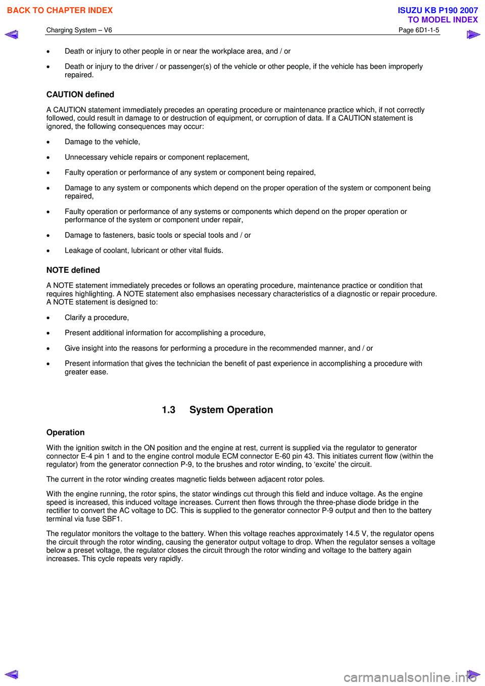
1.3 System Operation
Operation
W ith the ignition switch in the ON position and the engine at rest, current is supplied via the regulator to generator
connector E-4 pin 1 and to the engine control module ECM connector E-60 pin 43. This initiates current flow (within the
regulator) from the generator connection P-9, to the brushes and rotor winding, to ‘excite’ the circuit.
The current in the rotor winding creates magnetic fields between adjacent rotor poles.
W ith the engine running, the rotor spins, the stator windings cut through this field and induce voltage. As the engine
speed is increased, this induced voltage increases. Current then flows through the three-phase diode bridge in the
rectifier to convert the AC voltage to DC. This is supplied to the generator connector P-9 output and then to the battery
terminal via fuse SBF1.
The regulator monitors the voltage to the battery. W hen this voltage reaches approximately 14.5 V, the regulator opens
the circuit through the rotor winding, causing the generator output voltage to drop. W hen the regulator senses a voltage
below a preset voltage, the regulator closes the circuit through the rotor winding and voltage to the battery again
increases. This cycle repeats very rapidly.
BACK TO CHAPTER INDEX
TO MODEL INDEX
ISUZU KB P190 2007
Page 3593 of 6020
Charging System – V6 Page 6D1-1-6
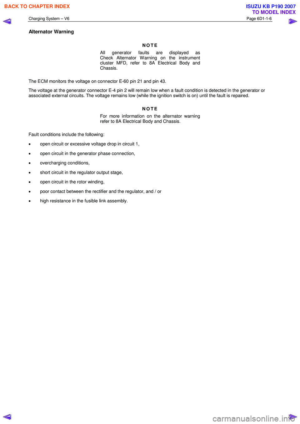
Alternator Warning
NOTE
All generator faults are displayed as
Check Alternator W arning on the instrument
cluster MFD, refer to 8A Electrical Body and
Chassis.
The ECM monitors the voltage on connector E-60 pin 21 and pin 43.
The voltage at the generator connector E-4 pin 2 will remain low when a fault condition is detected in the generator or
associated external circuits. The voltage remains low (while the ignition switch is on) until the fault is repaired.
NOTE
For more information on the alternator warning
refer to 8A Electrical Body and Chassis.
Fault conditions include the following:
• open circuit or excessive voltage drop in circuit 1,
• open circuit in the generator phase connection,
• overcharging conditions,
• short circuit in the regulator output stage,
• open circuit in the rotor winding,
• poor contact between the rectifier and the regulator, and / or
• high resistance in the fusible link assembly.
BACK TO CHAPTER INDEX
TO MODEL INDEX
ISUZU KB P190 2007
Page 3594 of 6020
Charging System – V6 Page 6D1-1-7
2 Diagnosis
2.1 Diagnostic General Information
Basic Diagnostic Tools Required
Use of incorrect electrical circuit diagnostic
tools when performing the generator
diagnostic procedures could result in
incorrect diagnostic results or damage to
components.
The following electrical circuit testing tools are required to perform the diagnostic procedures detailed in this Section:
• digital multimeter with 10 mega ohms impedance, and
• connector test adapter kit Tool No. KM609.
For further information on the use of these tools, refer to 8A Electrical Body and Chassis.
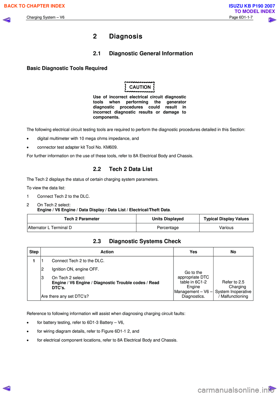
2.2 Tech 2 Data List
The Tech 2 displays the status of certain charging system parameters.
To view the data list:
1 Connect Tech 2 to the DLC.
2 On Tech 2 select: Engine / V6 Engine / Data Display / Data List / Electrical/Theft Data .
Tech 2 Parameter Units Displayed Typical Display Values
Alternator L Terminal D Percentage Various
2.3 Diagnostic Systems Check
Step Action Yes No
1 1 Connect Tech 2 to the DLC.
2 Ignition ON, engine OFF.
3 On Tech 2 select: Engine / V6 Engine / Diagnostic Trouble codes / Read
DTC’s.
Are there any set DTC’s? Go to the
appropriate DTC table in 6C1-2 Engine
Management – V6 – Diagnostics. Refer to 2.5
Charging
System Inoperative / Malfunctioning
Reference to following information will assist when diagnosing charging circuit faults:
• for battery testing, refer to 6D1-3 Battery – V6,
• for wiring diagram details, refer to Figure 6D1-1 2, and
• for electrical component locations, refer to 8A Electrical Body and Chassis.
BACK TO CHAPTER INDEX
TO MODEL INDEX
ISUZU KB P190 2007