2007 ISUZU KB P190 ignition
[x] Cancel search: ignitionPage 3597 of 6020
Charging System – V6 Page 6D1-1-10
3 Minor Service Operations
3.1 Safety Precautions
Observe the following precautions. Failure to observe these precautions will result in serious damage to the generator.
• Only use the generator and voltage regulator in a negative ground system.
• Always refer to 1.2 W ARNING, CAUTION and NOTES before disconnecting the battery.
• W hen installing a battery, fit the positive (+) cable to the battery before fitting the negative cable.
• W hen a slave battery is used for starting purposes, ensure that both batteries are connected in parallel. That is,
positive terminals connected and negative terminals connected.
• Only use jumper leads that have surge protection.
• Disconnect both battery cables when charging the battery. This isolates the generator from the battery and from
the external charging equipment.
• Do not operate the generator within an open circuit or without a battery in the circuit.
• Do not disconnect the battery while the generator is running.
• Do not attempt to polarise the generator.
• Do not connect generator connector E-4 pin 1 to 12 V (the battery or ignition circuits).
• Some battery powered timing lights can produce high transient voltages when connected or disconnected.
Only disconnect or connect timing lights when the engine is switched off.
Ensure the generator connector E-4 pin 1 has
a maximum sinking current of 50mA.
3.2 Maintenance
Regular Checks
Check the following at regular intervals:
• generator terminals – for corrosion and loose connections,
• wiring – for continuity and damaged insulation,
• mounting bolts – for tightness,
• drive belt – for alignment and wear, and
• drive pulley – for damage and warping.
NOTE
The drive-belt adjustment for the engine
ancillaries (i.e. generator and water pump) is
provided by a spring-loaded tensioner. Therefore,
the drive belt does not require manual
adjustment.
Lubrication
High tolerance bearings are used in this generator. If the bearings are removed during the generator disassembly, new
bearings must be installed to restore the generator to original specification. The ball bearings supporting the rotor shaft
are pre-lubricated and sealed. Do not attempt to lubricate these during servicing.
BACK TO CHAPTER INDEX
TO MODEL INDEX
ISUZU KB P190 2007
Page 3598 of 6020
Charging System – V6 Page 6D1-1-11
3.3 On-vehicle Testing
Generator On-vehicle Checks
Prerequisites
Before testing the generator output, ensure that:
• all generator circuit connections are clean and tight,
• the generator is always connected to the battery during testing (to prevent damage to the diodes),
• the battery is fully charged, and
• the specific gravity does not vary more than 0.025 between cells. (It is recommended the average specific gravity
is 1.260 or higher). Refer to 6D1-3 Battery – V6.
Carry out a load test on the battery to determine its ability to supply and accept current. This is a good indicator of the
general condition of the battery. For details of battery testing, refer to 6D1-3 Battery – V6.
Inspect the drive belt and tensioner markings to determine if the drive belt is within operating limits. Replace the belt if it
is excessively worn or outside the operating range of the tensioner.
For further details, refer to 6A1 Engine Mechanical – V6.
Generator Test
Regulating Voltage Test
NOTE
Leave the generator E-4 wiring harness
connector connected, as it provides initial field
excitation.
1 Ensure the ignition switch is in the OFF position and all electrical equipment is turned off.
Refer to 1.2 WARNING, CAUTION and
NOTES before disconnecting the battery.
2 Disconnect the battery ground cable P-5 at the battery.
3 Disconnect the generator positive lead P-9 from the generator . Connect the positive lead of a multimeter
set to measure current (1) to P-9 (2).
4 Connect that multimeter’s negative lead to the disconnected generator positive lead (3).
5 Connect the positive lead of a multimeter set to measure voltage (4) to P-9 (5).
6 Connect that multimeter’s negative lead to a good ground connection on the generator housing (6).
Insulate the terminal of the generator
positive lead P-9 to prevent contact with any
metal part of the vehicle. If the terminal is
grounded, damage to the charging circuit
can result when the battery is reconnected.
Figure 6D1-1 3
BACK TO CHAPTER INDEX
TO MODEL INDEX
ISUZU KB P190 2007
Page 3603 of 6020
Charging System – V6 Page 6D1-1-16
Reinstall
Reinstallation of the generator is the reverse of the removal procedure, noting the following:
1 Tighten all fasteners to the correct torque specification.
2 Reconnect the battery ground lead.
3 Start the engine.
4 Check the generator warning indicator operation.
5 Check the drive belt is correctly routed and aligned.
6 Check the generator output. Refer to 3.3 On-vehicle Testing.
7 Check the voltage regulator operation. Refer to 3.3 On-vehicle Testing.
8 Turn the ignition switch off.
Generator mounting bolts ........................... (1) 58.0 Nm
Generator mounting bolts ........................... (2) 58.0 Nm
Generator mounting bolts ........................... (4) 58.0 Nm
Battery harness to P-9 pin B nut
torque specification ...................................7.1 – 13.3 Nm
BACK TO CHAPTER INDEX
TO MODEL INDEX
ISUZU KB P190 2007
Page 3612 of 6020
Starting System – V6 Page 6D1-2–4
• Clarify a procedure,
• Present additional information for accomplishing a procedure,
• Give insight into the reasons for performing a procedure in the recommended manner, and / or
Present information that gives the technician the benefit of past experience in accomplishing a procedure with greater
ease.
1.2 Components
Starting System Components
The main components of the starting system are:
• battery,
• wiring,
• ignition switch,
• theft deterrent engine crank inhibitor (a function of the theft deterrent system),
• park / neutral and back-up switch (on vehicles with 4 speed automatic transmission),
• engine control module (ECM),
• start relay,
• solenoid switch, and
• starter motor.
Starter Motor and Solenoid Switch Components
Solenoid Switch
The solenoid switch is used to activate the DC motor and has two windings; the pull-in winding and the hold-in winding.
The pull-in winding has heavier wire and is grounded through the DC motor winding and brushes. The hold-in winding is
grounded through the solenoid casing.
Planetary Drive Train
The planetary drive train consists of an internally toothed ring gear and three planetary gear wheels, which rotate on
sleeve bearings on the planetary drive shaft. The ring gear is keyed into the drive-end housing and is made from
high-grade polyamide with mineral additives.
W hen the starter motor operates, the armature turns the planetary gears inside the fixed planetary ring gear. This drives
the planetary shaft at a reduced speed ratio which turns the drive assembly. A fork lever in the drive-end housing forces
the drive assembly forward to engage with the flexplate / flywheel ring gear on the engine and transmit cranking torque.
An internal clutch allows the drive assembly pinion gear to rotate freely when the engine starts. This prevents the
armature from being driven at excessive speed by the engine.
Armature
The armature shaft is supported at each end by oil absorbent, sintered metal bushes; one in the commutator end shield
and one in the planetary drive shaft. The front end of the armature has a gear profile. This meshes with the three
planetary gear wheels. These in turn, mesh with the internal teeth of the ring gear.
Brushes
A brush plate supports four commutator brushes. This plate is fixed to the commutator end shield with two retaining
screws. Two negative brushes are grounded to the pole housing. The two positive brushes are insulated from the pole
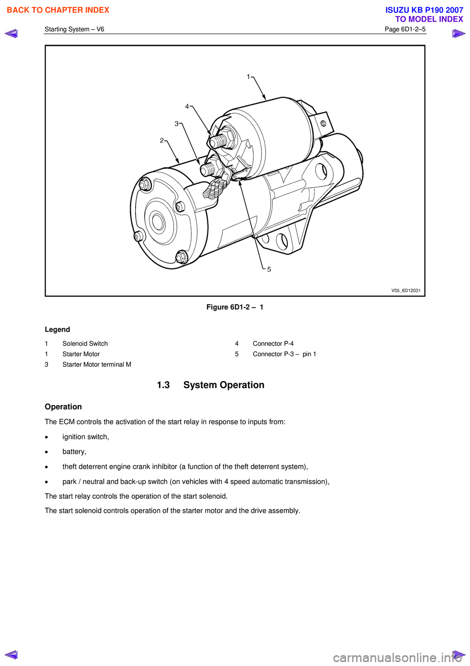
housing and connected to the solenoid switch M terminal, refer to Figure 6D1-2 – 1.
BACK TO CHAPTER INDEX
TO MODEL INDEX
ISUZU KB P190 2007
Page 3613 of 6020
Starting System – V6 Page 6D1-2–5
Figure 6D1-2 – 1
Legend
1 Solenoid Switch
1 Starter Motor
3 Starter Motor terminal M 4 Connector P-4
5 Connector P-3 – pin 1
1.3 System Operation
Operation
The ECM controls the activation of the start relay in response to inputs from:
• ignition switch,
• battery,
• theft deterrent engine crank inhibitor (a function of the theft deterrent system),
• park / neutral and back-up switch (on vehicles with 4 speed automatic transmission),
The start relay controls the operation of the start solenoid.
The start solenoid controls operation of the starter motor and the drive assembly.
BACK TO CHAPTER INDEX
TO MODEL INDEX
ISUZU KB P190 2007
Page 3614 of 6020
Starting System – V6 Page 6D1-2–6
Sequence of Operation
1 W hen the ignition switch is turned to the START position, a signal is also sent to the ECM to request the engine to
crank.
• For automatic vehicles the transmission must be in either park (P) or neutral (N) for the ECM to allow
cranking to commence.
• The ECM will only allow cranking if the battery voltage is above the minimum battery voltage threshold value,
refer to 6C1-1 Engine Management – V6 – General Information for further information.
2 The ECM operates the start relay which provides power to the pull-in winding of the start solenoid.
3 Current flow to the pull-in winding develops powerful magnetism which pulls in the solenoid switch plunger.
4 The plunger closes the switch contacts connecting battery voltage to the DC motor and pivots the fork lever to engage the drive assembly to the flexplate / flywheel ring gear. Closing the solenoid switch contacts deactivates the
pull-in winding, the hold-in winding remains active.
5 W ith the solenoid switch contacts closed, current flows from the battery through the DC motor, which rotates the armature at high speed and provides cranking torque.
BACK TO CHAPTER INDEX
TO MODEL INDEX
ISUZU KB P190 2007
Page 3615 of 6020
Starting System – V6 Page 6D1-2–7
2 Diagnostics
2.1 Diagnostic General Information
NOTE
There is a minimum battery voltage threshold
value. If the battery voltage is below the set value,
the ECU will inhibit cranking. Refer to 6C1-1
Engine Management – V6 – General Information
for further information.
Basic Diagnostic Tools Required
Use of incorrect electrical circuit diagnostic
tools when performing the cruise control
diagnostic procedures could result in
incorrect diagnostic results or damage to
components.
The following electrical circuit testing tools are required to perform the diagnostic procedures detailed in this Section:
• digital multimeter with 10 meg ohms impedance, and
• connector test adapter kit Tool No. KM609.
For further information on the use of these tools, refer to 8A Electrical Body and Chassis.
2.2 Tech 2 Data List
The Tech 2 displays the status of certain starting system parameters.
To view the data list:
1 Connect Tech 2 to the DLC.
2 On Tech 2 select: Engine / V6 Engine / Data Display / Data List / Electrical / Theft Data .
Tech 2 Parameter Units Displayed Typical Display Values
Crank Request Inactive / Active Inactive
Starter Relay Off / On Off
2.3 Diagnostic Systems Check
Step Action Yes No
1
Is the fault specifically isolated to this system / module?
Go to Step 2 Go to 0D Vehicle
Diagnostics
2 1 Connect Tech 2 to the DLC.
2 Ignition ON, engine OFF.
3 On Tech 2 select:
Engine / V6 Engine / Diagnostic Trouble codes / Read
DTC’s.
Are there any set DTC’s? Go to the
appropriate DTC
table in 6C1-2 Engine
Management – V6 – Diagnostics. Refer to 2.5
Starting
System Inoperative / Malfunctioning
BACK TO CHAPTER INDEX
TO MODEL INDEX
ISUZU KB P190 2007
Page 3618 of 6020
Starting System – V6 Page 6D1-2–10
2.5 Starting System Inoperative /
Malfunctioning
Circuit Description
The battery cable supplies a constant connection from the battery to starter solenoid connector P – 4.
W hen the ignition switch is turned to the START position, 12 V is applied to the ECM connector C – 56 pin 31.
For vehicles with 4 speed automatic transmission, when the transmission is in park (P) or neutral (N), the park / neutral
and back-up switch grounds ECM connector C – 56 pin 32.
The ECM provides a ground for the start relay, ECM connector C – 56 pin 35 to start relay connector X – 13 pin 5.
W hen activated the start relay provides 12 V to starter solenoid connector P – 3 pin 1.
The solenoid closes its switch contacts to connect the battery voltage at the solenoid switch terminal P – 4 terminal B to
the DC motor. The pull-in winding of the solenoid switch is grounded through the DC motor winding and brushes. The
hold-in winding is grounded through the solenoid casing. The DC motor is grounded through the starter motor casing.
Refer to 2.4 W iring Diagram to aid in diagnosis.
Diagnostic Table Notes
Reference to following information will assist when diagnosing starting circuit faults:
1 If the battery, starter motor and fuel system are deemed as serviceable and a ‘no crank’ and / or ‘no start’ condition exists, refer to the following Sections as required:
a 11A Immobiliser for theft deterrent engine crank inhibitor related faults
b 6C1-2 Engine Management V6 Diagnostics, for starter relay circuit faults
2 For all wiring harness fault diagnoses, refer to 8A Electrical Body and Chassis.
3 For wiring harness repairs, refer to 8A Electrical Body and Chassis.
4 Refer to 8A Electrical Body and Chassis for harness routing.
5 Ensure the battery, cables and connections are in good order. Refer to 8A Electrical Body and Chassis.
Diagnostic Table
Step Action Yes No
1
Did you review 1.3 System Operation?
Go to Step 2 Go to 1.3
System
Operation
2 Did you read 2.3 Diagnostic Systems Check
Go to Step 3 Go to 2.3
Diagnostic Systems Check
3 Turn the ignition switch to the START position and then release it.
Did the engine crank or were there any clicking or chattering sounds
from the solenoid? Go to Diagnostic
Table – Slow
Cranking, Solenoid Clicks or Chatters Go to Step 4
4 Inspect fusible link SBF9, refer to 8A Electrical Body and Chassis.
Is fusible link SBF9 blown? Replace the faulty
fusible link (refer to
Note 3).
If the fusible link
blows again, repair
or replace the circuit from SBF9 to the
starter relay X – 13 pin 1 or ignition
switch B – 62 pin 2 (refer to Note 2) Go to Step 5
BACK TO CHAPTER INDEX
TO MODEL INDEX
ISUZU KB P190 2007