2007 ISUZU KB P190 ignition
[x] Cancel search: ignitionPage 3651 of 6020
Battery Page 6D1-3–11
b W ait 15 seconds for the battery to recover.
8 If possible, set the selector to 50% of rapid discharge current (or three times the 20 hour discharge rate).
9 Apply the load test for 10 seconds and record the battery voltage. If one cell is faulty it will gas excessively or overheat. This indicates a faulty battery.
10 Recharge the battery if the voltage is at or below the minimum voltage specified by the HRD manufacturer (or 9.6 V).
11 Replace the battery if the voltage is below the minimum voltage specified by the HRD manufacturer (or below 9.6 V after the battery is charged and the test is repeated). Refer to 4.1 Battery.
12 Connect the battery positive terminal.
13 Connect the battery negative terminal.
Alternate Load Test
If HRD test equipment is not available, test the battery as follows:
1 Read and obey the safety precautions for working with batteries, refer to 2 Safety Precautions.
2 Ensure the state of the battery is at least 65% charged. Refer to 3.3 Hydrometer Test.
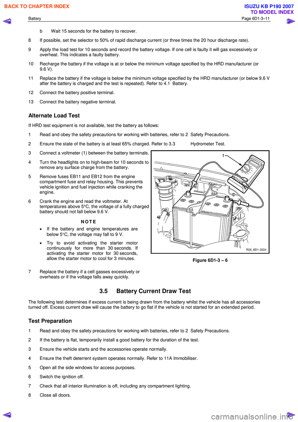
3 Connect a voltmeter (1) between the battery terminals.
4 Turn the headlights on to high-beam for 10 seconds to remove any surface charge from the battery.
5 Remove fuses EB11 and EB12 from the engine compartment fuse and relay housing. This prevents
vehicle ignition and fuel injection while cranking the
engine.
6 Crank the engine and read the voltmeter. At temperatures above 5°C, the voltage of a fully charged
battery should not fall below 9.6 V.
NOTE
• If the battery and engine temperatures are
below 5 °C, the voltage may fall to 9 V.
• Try to avoid activating the starter motor
continuously for more than 30 seconds. If
activating the starter motor for 30 seconds,
allow the starter motor to cool for 3 minutes.
7 Replace the battery if a cell gasses excessively or overheats or if the voltage falls away quickly.
Figure 6D1-3 – 6
3.5 Battery Current Draw Test
The following test determines if excess current is being drawn from the battery whilst the vehicle has all accessories
turned off. Excess current draw will cause the battery to go flat if the vehicle is not started for an extended period.
Test Preparation
1 Read and obey the safety precautions for working with batteries, refer to 2 Safety Precautions.
2 If the battery is flat, temporarily install a good battery for the duration of the test.
3 Ensure the vehicle starts and the accessories operate normally.
4 Ensure the theft deterrent system operates normally. Refer to 11A Immobiliser.
5 Open all the side windows for access purposes.
6 Switch the ignition off.
7 Check that all interior illumination is off, including any compartment lighting.
8 Close all doors.
BACK TO CHAPTER INDEX
TO MODEL INDEX
ISUZU KB P190 2007
Page 3652 of 6020
Battery Page 6D1-3–12
9 Lock the doors and activate the theft deterrent system to arm the vehicle.
10 If the multimeter contains fuses, check they are serviceable.
Test Procedure
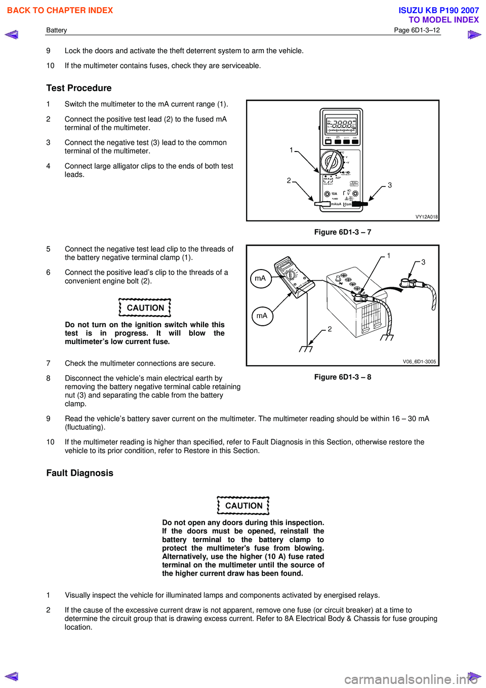
1 Switch the multimeter to the mA current range (1).
2 Connect the positive test lead (2) to the fused mA terminal of the multimeter.
3 Connect the negative test (3) lead to the common terminal of the multimeter.
4 Connect large alligator clips to the ends of both test leads.
Figure 6D1-3 – 7
5 Connect the negative test lead clip to the threads of the battery negative terminal clamp (1).
6 Connect the positive lead’s clip to the threads of a convenient engine bolt (2).
Do not turn on the ignition switch while this
test is in progress. It will blow the
multimeter’s low current fuse.
7 Check the multimeter connections are secure.
8 Disconnect the vehicle’s main electrical earth by removing the battery negative terminal cable retaining
nut (3) and separating the cable from the battery
clamp.
Figure 6D1-3 – 8
9 Read the vehicle’s battery saver current on the multimeter. The multimeter reading should be within 16 – 30 mA (fluctuating).
10 If the multimeter reading is higher than specified, refer to Fault Diagnosis in this Section, otherwise restore the vehicle to its prior condition, refer to Restore in this Section.
Fault Diagnosis
Do not open any doors during this inspection.
If the doors must be opened, reinstall the
battery terminal to the battery clamp to
protect the multimeter's fuse from blowing.
Alternatively, use the higher (10 A) fuse rated
terminal on the multimeter until the source of
the higher current draw has been found.
1 Visually inspect the vehicle for illuminated lamps and components activated by energised relays.
2 If the cause of the excessive current draw is not apparent, remove one fuse (or circuit breaker) at a time to determine the circuit group that is drawing excess current. Refer to 8A Electrical Body & Chassis for fuse grouping
location.
BACK TO CHAPTER INDEX
TO MODEL INDEX
ISUZU KB P190 2007
Page 3657 of 6020

Battery Page 6D1-3–17
4 Turn off the ignition, lights and all other electrical loads.
5 Check the battery filler caps on both batteries are tight.
6 Place a wet cloth over the battery filler caps of each battery.
7 Attach one end of the red jumper cable to the positive terminal of the booster battery.
8 Attach the other end of the same cable to the positive terminal of the discharged battery.
9 Attach one end of the black jumper cable to the negative terminal of the booster battery.
10 Attach the other end to a solid stationary, metallic point on the engine of the disabled vehicle.
NOTE
Do not connect this end directly to the negative
post of the discharged battery.
Figure 6D1-3 – 10
Legend
Order of hook-up:
1 Booster vehicle, positive terminal
2 Disabled vehicle, positive terminal
3 Booster vehicle, negative terminal
4 Disabled vehicle, engine ground point Booster vehicle
Disabled vehicle
11 Ensure the jumper cables are not on or near drive pulleys, cooling fans or other points that will move when the engine is started.
12 Start the engine in the booster vehicle and run the engine at a moderate speed for a few minutes.
13 Start the engine in the disabled vehicle.
NOTE
If the engine in the disabled vehicle does not start
within 30 seconds, stop cranking the engine and
fix the cause. Refer to 3 Diagnosis.
14 W hen the engine starts, allow both engines to idle for approximately seven minutes. This allows the voltage levels in both vehicles to balance.
15 Leave the vehicles running and remove the jumper cables in the reverse sequence to attaching them. W hen removing each clamp, take care to ensure that it does not touch any other metal.
16 Discard the wet cloths covering the battery filler caps of both batteries.
BACK TO CHAPTER INDEX
TO MODEL INDEX
ISUZU KB P190 2007
Page 3676 of 6020
Powertrain Interface Module – V6 Page 6E1–15
4 Diagnostics
4.1 Diagnostic General Descriptions
The powertrain interface module (PIM) diagnostic procedure is organised in a logical structure that begins with the
Diagnostic System Check. The Diagnostic System Check directs the diagnostic procedure to the logical steps or
appropriate diagnostic table required to diagnose a PIM fault condition.
The diagnostic tables locate a faulty circuit or component through a logical based process of elimination. Correct use of
the diagnostic tables is essential to reduce diagnostic time and to prevent misdiagnosis.
In addition, the Diagnostic System Check provides the following information:
• identification of the PIM,
• condition of the diagnostic circuit, and
• identification and status of the DTCs if present.
Diagnostic Trouble Code (DTC) Tables
The diagnostic procedure is directed to a diagnostic trouble code (DTC) table if there are DTCs currently stored in the
PIM.
The diagnostic tables are designed to locate a faulty circuit or component through a logical based process of elimination.
The diagnostic tables are developed with the following assumptions:
• the vehicle functioned correctly at the time of assembly,
• there are no multiple faults, and
• the problem currently exists.
Multiple DTCs
W hen performing a DTC check and there are multiple DTCs, the diagnostic process must begin with the most likely DTC
that may trigger other DTCs.
Knowledge of the PIM and Tech 2 limitations are important to reduce diagnostic time and to prevent misdiagnosis. Refer
to 7.1 Diagnostic Requirements, Precautions and Preliminary Checks.
Diagnostic Trouble Codes (DTCs)
W hen the ignition switch is turned on, the PIM performs an internal integrity check that detects and isolates any internal
faults. The PIM also monitors the direct input switches such as the cruise control and the serial data bus for messages
from the control modules on the GM LAN bus. If a fault is detected by the PIM, it will log a Diagnostic Trouble Code
(DTC) that represents the fault detected. The DTCs stored in the PIM may be accessed using Tech 2.
Status of DTCs
The PIM designates the DTCs logged into a Current or History DTC.
Current DTCs
If the fault condition that triggers the DTC is present during the last PIM self test, that DTC will be designated as a current
DTC.
History DTCs
If the fault condition that triggers the DTC is not present during the last PIM self test, that DTC will be designated as a
history DTC.
Conditions for Clearing DTCs
• If there is no DTC logged in the current PIM self test, the current DTC will be cleared.
• If there is no DTC logged after 100 consecutive drive cycles, the history DTC will be cleared.
BACK TO CHAPTER INDEX
TO MODEL INDEX
ISUZU KB P190 2007
Page 3687 of 6020
Powertrain Interface Module – V6 Page 6E1–26
Step Action Yes No
4
Using Tech 2, attempt to communicate with the PIM.
Does Tech 2 communicate with the PIM? Go to Step 5 Refer to
7.3 Powertrain Interface Module –
Module
Communication Check Failure
Diagnostic Table
5 Using Tech 2, view and record all DTCs.
Does Tech 2 display any DTCs? Go to Step 6 Refer to
Intermittent Fault Conditions.
6 Does DTC C0550 fail this ignition cycle? Refer to
9.1 DTC
C0550 – PIM
Internal Fault
Diagnostic Table Go to Step 7
7 Does DTC U2100 fail this ignition cycle? Refer to
9.2 DTC
U2100 – No
Communication
W ith CAN Bus (High Speed) Diagnostic
Table Go to Step 8
8 Does DTC U2106 fail this ignition cycle? Refer to
9.4 DTC
U2106 – CAN Bus
No Communication
W ith Transmission Control Module Go to Step 9
9
Does DTC U2105 fail this ignition cycle? Refer to
9.3 DTC
U2105 – CAN Bus
No Communication
W ith Engine Control Module Diagnostic
Table Go to Step 10
10 Does Tech 2 display multiple DTCs? Refer to
the DTC Table of
the fault condition
that is most likely to
trigger multiple
DTCs. Refer to
4.1 Diagnostic General
Descriptions for information on
multiple DTCs fault condition Refer to the relevant
DTC table
When all diagnosis and repairs are completed, clear all DTCs and check the system for correct operation.
BACK TO CHAPTER INDEX
TO MODEL INDEX
ISUZU KB P190 2007
Page 3688 of 6020
Powertrain Interface Module – V6 Page 6E1–27
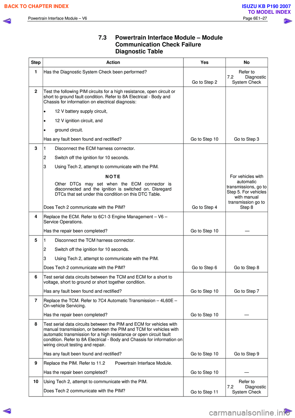
7.3 Powertrain Interface Module – Module
Communication Check Failure
Diagnostic Table
Step Action Yes No
1
Has the Diagnostic System Check been performed?
Go to Step 2 Refer to
7.2 Diagnostic System Check
2 Test the following PIM circuits for a high resistance, open circuit or
short to ground fault condition. Refer to 8A Electrical - Body and
Chassis for information on electrical diagnosis:
• 12 V battery supply circuit,
• 12 V ignition circuit, and
• ground circuit.
Has any fault been found and rectified? Go to Step 10 Go to Step 3
3 1 Disconnect the ECM harness connector.
2 Switch off the ignition for 10 seconds.
3 Using Tech 2, attempt to communicate with the PIM.
NOTE
Other DTCs may set when the ECM connector is
disconnected and the ignition is switched on. Disregard
DTCs that set under this condition on this DTC Table.
Does Tech 2 communicate with the PIM? Go to Step 4 For vehicles with
automatic
transmissions, go to
Step 5. For vehicles with manual
transmission go to Step 8
4 Replace the ECM. Refer to 6C1-3 Engine Management – V6 –
Service Operations.
Has the repair been completed? Go to Step 10 —
5 1 Disconnect the TCM harness connector.
2 Switch off the ignition for 10 seconds.
3 Using Tech 2, attempt to communicate with the PIM.
Does Tech 2 communicate with the PIM? Go to Step 6 Go to Step 8
6 Test serial data circuits between the TCM and ECM for a short to
voltage, short to ground or short together condition.
Has any fault been found and rectified? Go to Step 10 Go to Step 7
7 Replace the TCM. Refer to 7C4 Automatic Transmission – 4L60E –
On-vehicle Servicing.
Has the repair been completed? Go to Step 10 —
8 Test serial data circuits between the PIM and ECM for vehicles with
manual transmission, or between the PIM and TCM for vehicles with
automatic transmission for a high resistance or open circuit fault
condition. Refer to 8A Electrical - Body and Chassis for information on
wiring circuit testing and repair.
Has any fault been found and rectified? Go to Step 10 Go to Step 9
9 Replace the PIM. Refer to 11.2 Powertrain Interface Module.
Has the repair been completed? Go to Step 10 —
10 Using Tech 2, attempt to communicate with the PIM.
Does Tech 2 communicate with the PIM? Go to Step 11 Refer to
7.2 Diagnostic System Check
BACK TO CHAPTER INDEX
TO MODEL INDEX
ISUZU KB P190 2007
Page 3689 of 6020
Powertrain Interface Module – V6 Page 6E1–28
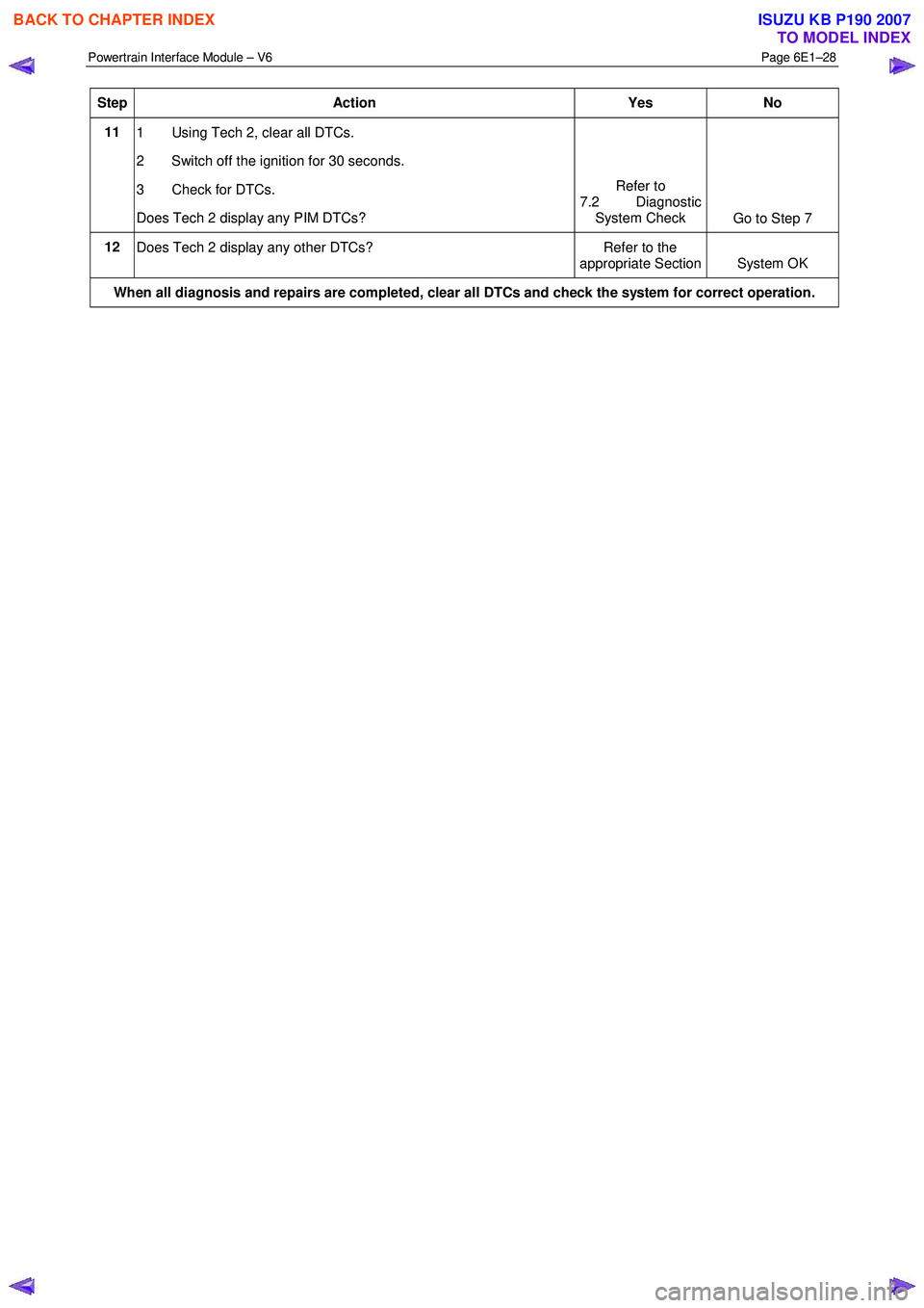
Step Action Yes No
11
1 Using Tech 2, clear all DTCs.
2 Switch off the ignition for 30 seconds.
3 Check for DTCs.
Does Tech 2 display any PIM DTCs? Refer to
7.2 Diagnostic System Check Go to Step 7
12
Does Tech 2 display any other DTCs? Refer to the
appropriate Section System OK
When all diagnosis and repairs are completed, clear all DTCs and check the system for correct operation.
BACK TO CHAPTER INDEX
TO MODEL INDEX
ISUZU KB P190 2007
Page 3692 of 6020
Powertrain Interface Module – V6 Page 6E1–31
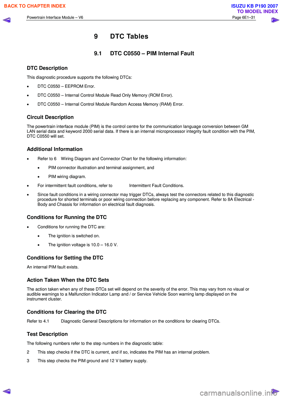
9 DTC Tables
9.1 DTC C0550 – PIM Internal Fault
DTC Description
This diagnostic procedure supports the following DTCs:
• DTC C0550 – EEPROM Error.
• DTC C0550 – Internal Control Module Read Only Memory (ROM Error).
• DTC C0550 – Internal Control Module Random Access Memory (RAM) Error.
Circuit Description
The powertrain interface module (PIM) is the control centre for the communication language conversion between GM
LAN serial data and keyword 2000 serial data. If there is an internal microprocessor integrity fault condition with the PIM,
DTC C0550 will set.
Additional Information
• Refer to 6 W iring Diagram and Connector Chart for the following information:
• PIM connector illustration and terminal assignment, and
• PIM wiring diagram.
• For intermittent fault conditions, refer to Intermittent Fault Conditions.
• Since fault conditions in a wiring connector may trigger DTCs, always test the connectors related to this diagnostic
procedure for shorted terminals or poor wiring connection before replacing any component. Refer to 8A Electrical -
Body and Chassis for information on electrical fault diagnosis.
Conditions for Running the DTC
• Conditions for running the DTC are:
• The ignition is switched on.
• The ignition voltage is 10.0 – 16.0 V.
Conditions for Setting the DTC
An internal PIM fault exists.
Action Taken When the DTC Sets
The action taken when any of these DTCs set will depend on the severity of the error. This may vary from no visual or
audible warnings to a Malfunction Indicator Lamp and / or Service Vehicle Soon warning lamp displayed on the
instrument cluster.
Conditions for Clearing the DTC
Refer to 4.1 Diagnostic General Descriptions for information on the conditions for clearing DTCs.
Test Description
The following numbers refer to the step numbers in the diagnostic table:
2 This step checks if the DTC is current, and if so, indicates the PIM has an internal problem.
3 This step checks the PIM ground and 12 V battery supply.
BACK TO CHAPTER INDEX
TO MODEL INDEX
ISUZU KB P190 2007