2007 ISUZU KB P190 ignition
[x] Cancel search: ignitionPage 3521 of 6020
Engine Management – V6 – Diagnostics Page 6C1-2–243
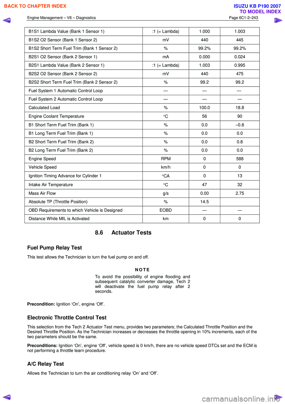
B1S1 Lambda Value (Bank 1 Sensor 1) :1 (= Lambda) 1.000 1.003
B1S2 O2 Sensor (Bank 1 Sensor 2) mV 440 445
B1S2 Short Term Fuel Trim (Bank 1 Sensor 2) % 99.2% 99.2%
B2S1 O2 Sensor (Bank 2 Sensor 1) mA 0.000 0.024
B2S1 Lambda Value (Bank 2 Sensor 1) :1 (= Lambda) 1.003 0.995
B2S2 O2 Sensor (Bank 2 Sensor 2) mV 440 475
B2S2 Short Term Fuel Trim (Bank 2 Sensor 2) % 99.2 99.2
Fuel System 1 Automatic Control Loop — — —
Fuel System 2 Automatic Control Loop — — —
Calculated Load % 100.0 18.8
Engine Coolant Temperature
°C 56 90
B1 Short Term Fuel Trim (Bank 1)
% 0.0 –0.8
B1 Long Term Fuel Trim (Bank 1) % 0.0 0.0
B2 Short Term Fuel Trim (Bank 2) % 0.0 0.8
B2 Long Term Fuel Trim (Bank 2) % 0.0 0.0
Engine Speed RPM 0 588
Vehicle Speed km/h 0 0
Ignition Timing Advance for Cylinder 1
°CA 0 13
Intake Air Temperature
°C 47 32
Mass Air Flow
g/s 0.00 2.75
Absolute TP (Throttle Position) % 14.5
OBD Requirements to which Vehicle is Designed EOBD — —
Distance W hile MIL is Activated km 0 0
8.6 Actuator Tests
Fuel Pump Relay Test
This test allows the Technician to turn the fuel pump on and off.
NOTE
To avoid the possibility of engine flooding and
subsequent catalytic converter damage, Tech 2
will deactivate the fuel pump relay after 2
seconds.
Precondition: Ignition ‘On’, engine ‘Off’.
Electronic Throttle Control Test
This selection from the Tech 2 Actuator Test menu, provides two parameters; the Calculated Throttle Position and the
Desired Throttle Position. As the Technician increases or decreases the throttle opening in 10% increments, each of the
two parameters should be the same.
Preconditions: Ignition ‘On’, engine ‘Off’, vehicle speed is 0 km/h, there are no vehicle speed DTCs set and the ECM is
not performing a throttle learn procedure.
A/C Relay Test
Allows the Technician to turn the air conditioning relay ‘On’ and ‘Off’.
BACK TO CHAPTER INDEX
TO MODEL INDEX
ISUZU KB P190 2007
Page 3522 of 6020
Engine Management – V6 – Diagnostics Page 6C1-2–244
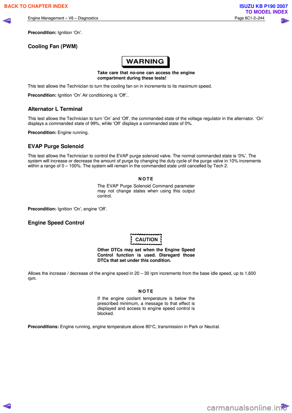
Precondition: Ignition ‘On’.
Cooling Fan (PWM)
Take care that no-one can access the engine
compartment during these tests!
This test allows the Technician to turn the cooling fan on in increments to its maximum speed.
Precondition: Ignition ‘On’ Air conditioning is ‘Off’..
Alternator L Terminal
This test allows the Technician to turn ‘On’ and ‘Off’, the commanded state of the voltage regulator in the alternator. ‘On’
displays a commanded state of 99%, while ‘Off’ displays a commanded state of 0%.
Precondition: Engine running.
EVAP Purge Solenoid
This test allows the Technician to control the EVAP purge solenoid valve. The normal commanded state is ‘0%’. The
system will increase or decrease the amount of purge by changing the duty cycle of the purge valve in 10% increments
within a range of 0 – 100%. The system will remain in the commanded state until cancelled by Tech 2.
NOTE
The EVAP Purge Solenoid Command parameter
may not change states when using this output
control.
Precondition: Ignition ‘On’, engine ‘Off’.
Engine Speed Control
Other DTCs may set when the Engine Speed
Control function is used. Disregard those
DTCs that set under this condition.
Allows the increase / decrease of the engine speed in 20 – 30 rpm increments from the base idle speed, up to 1,600
rpm.
NOTE
If the engine coolant temperature is below the
prescribed minimum, a message to that effect is
displayed and access to engine speed control is
blocked.
Preconditions: Engine running, engine temperature above 80 °C, transmission in Park or Neutral.
BACK TO CHAPTER INDEX
TO MODEL INDEX
ISUZU KB P190 2007
Page 3523 of 6020
Engine Management – V6 – Diagnostics Page 6C1-2–245
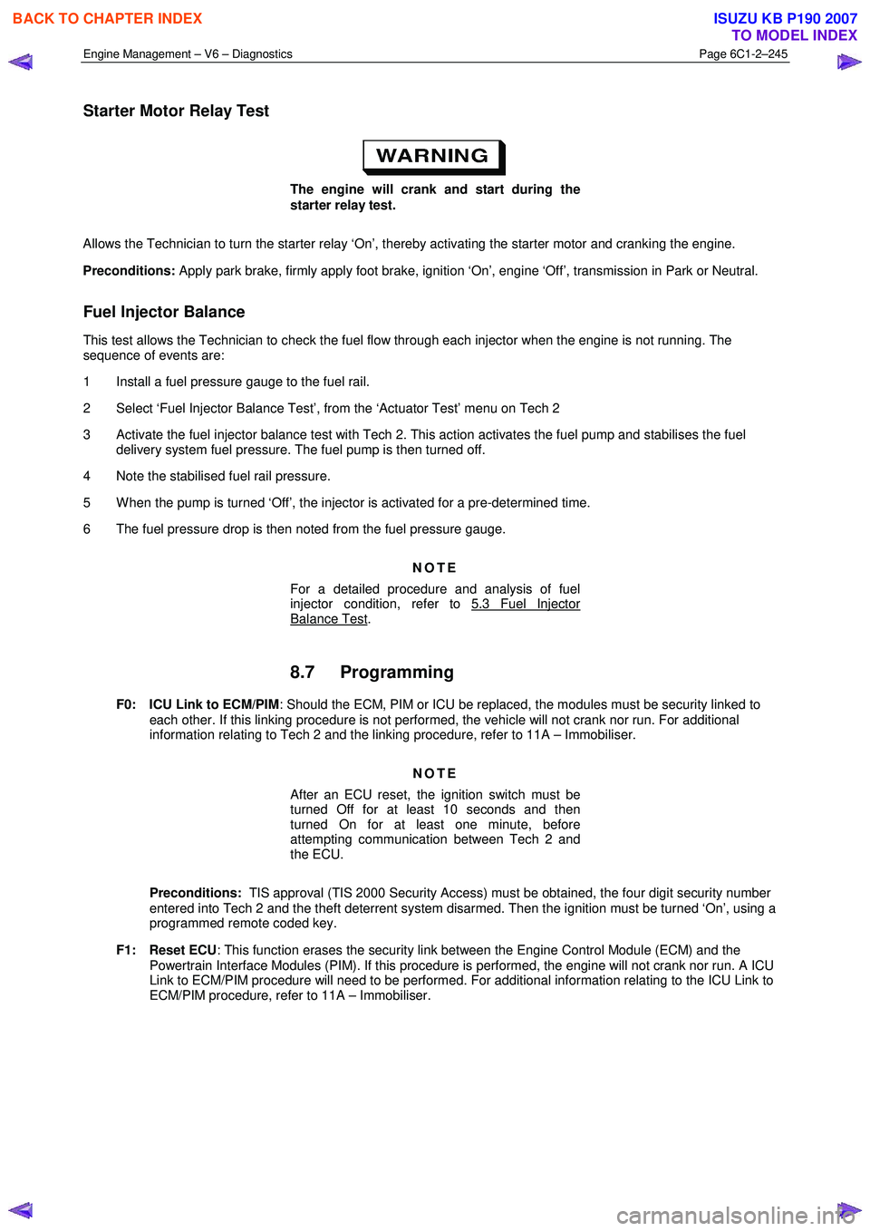
Starter Motor Relay Test
The engine will crank and start during the
starter relay test.
Allows the Technician to turn the starter relay ‘On’, thereby activating the starter motor and cranking the engine.
Preconditions: Apply park brake, firmly apply foot brake, ignition ‘On’, engine ‘Off’, transmission in Park or Neutral.
Fuel Injector Balance
This test allows the Technician to check the fuel flow through each injector when the engine is not running. The
sequence of events are:
1 Install a fuel pressure gauge to the fuel rail.
2 Select ‘Fuel Injector Balance Test’, from the ‘Actuator Test’ menu on Tech 2
3 Activate the fuel injector balance test with Tech 2. This action activates the fuel pump and stabilises the fuel delivery system fuel pressure. The fuel pump is then turned off.
4 Note the stabilised fuel rail pressure.
5 W hen the pump is turned ‘Off’, the injector is activated for a pre-determined time.
6 The fuel pressure drop is then noted from the fuel pressure gauge.
NOTE
For a detailed procedure and analysis of fuel
injector condition, refer to 5.3 Fuel Injector
Balance Test.
8.7 Programming
F0: ICU Link to ECM/PIM : Should the ECM, PIM or ICU be replaced, the modules must be security linked to
each other. If this linking procedure is not performed, the vehicle will not crank nor run. For additional
information relating to Tech 2 and the linking procedure, refer to 11A – Immobiliser.
NOTE
After an ECU reset, the ignition switch must be
turned Off for at least 10 seconds and then
turned On for at least one minute, before
attempting communication between Tech 2 and
the ECU.
Preconditions: TIS approval (TIS 2000 Security Access) must be obtained, the four digit security number
entered into Tech 2 and the theft deterrent system disarmed. Then the ignition must be turned ‘On’, using a
programmed remote coded key.
F1: Reset ECU : This function erases the security link between the Engine Control Module (ECM) and the
Powertrain Interface Modules (PIM). If this procedure is performed, the engine will not crank nor run. A ICU
Link to ECM/PIM procedure will need to be performed. For additional information relating to the ICU Link to
ECM/PIM procedure, refer to 11A – Immobiliser.
BACK TO CHAPTER INDEX
TO MODEL INDEX
ISUZU KB P190 2007
Page 3524 of 6020
Engine Management – V6 – Diagnostics Page 6C1-2–246
NOTE
After an ECU reset, the ignition switch must be
turned Off for at least 10 seconds and then
turned On for at least one minute, before
attempting communication between Tech 2 and
the ECU.
Preconditions: The four digit security code must be entered into Tech 2 and the theft deterrent system
must be disarmed and the ignition switched ‘On’ with a programmed remote coded key.
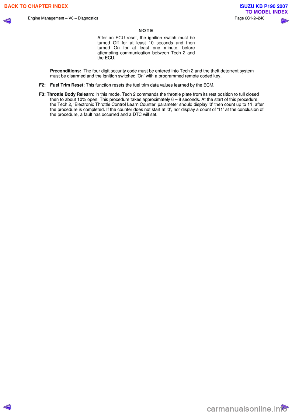
F2: Fuel Trim Reset : This function resets the fuel trim data values learned by the ECM.
F3: Throttle Body Relearn : In this mode, Tech 2 commands the throttle plate from its rest position to full closed
then to about 10% open. This procedure takes approximately 6 – 8 seconds. At the start of this procedure,
the Tech 2, ‘Electronic Throttle Control Learn Counter’ parameter should display ‘0’ then count up to 11, after
the procedure is completed. If the counter does not start at ‘0’, nor display a count of ‘11’ at the conclusion of
the procedure, a fault has occurred and a DTC will set.
BACK TO CHAPTER INDEX
TO MODEL INDEX
ISUZU KB P190 2007
Page 3526 of 6020
Engine Management – V6 – Service Operations Page 6C1-3–2
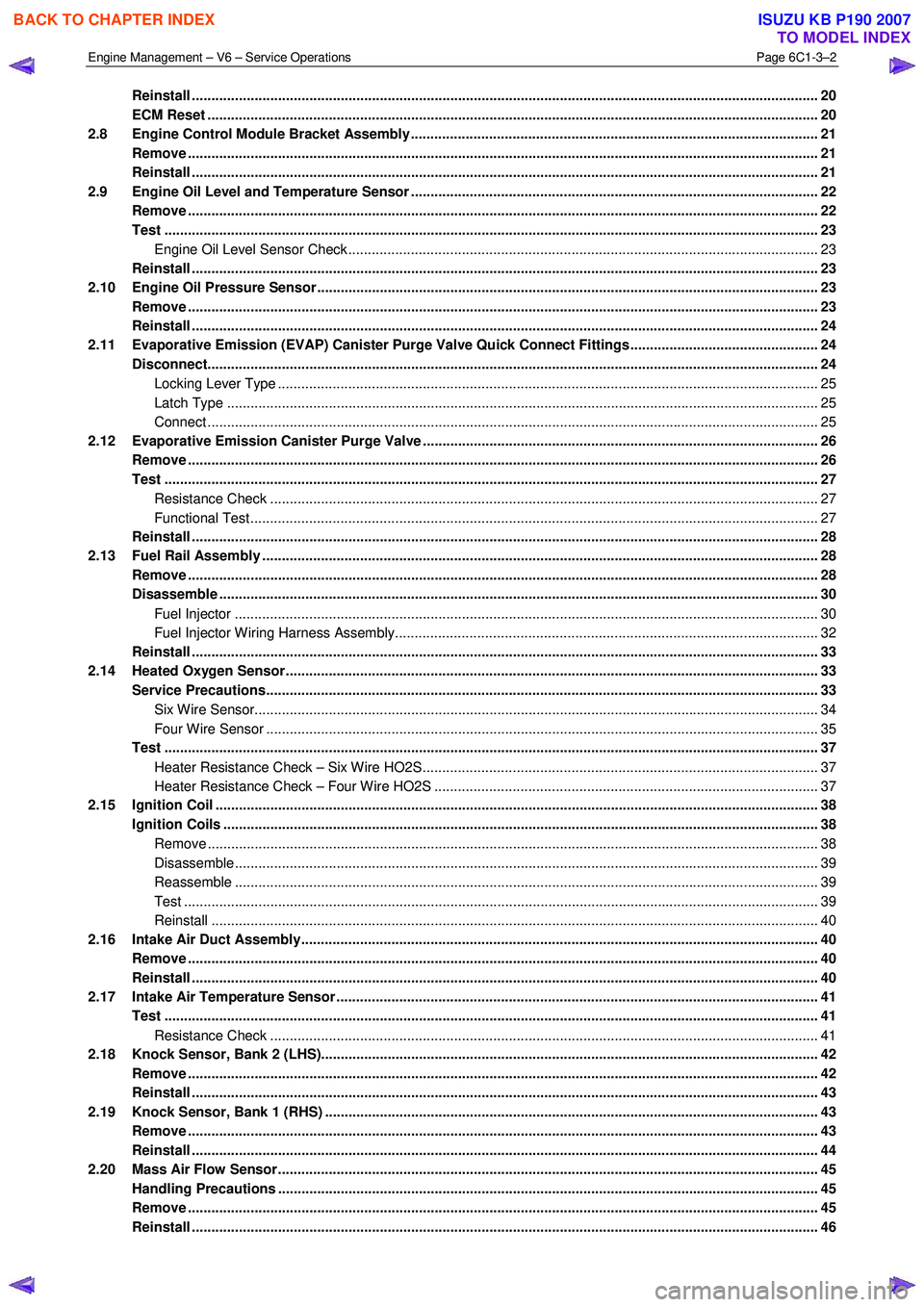
Reinstall ................................................................................................................................................................ 20
ECM Reset ...................................................................................................................... ...................................... 20
2.8 Engine Control Module Bracket Assembly......................................................................................... ............... 21
Remove ................................................................................................................................................................. 21
Reinstall ................................................................................................................................................................ 21
2.9 Engine Oil Level and Temperature Sensor ........................................................................................ ................ 22
Remove ................................................................................................................................................................. 22
Test ....................................................................................................................................................................... 23
Engine Oil Level Sensor Check .................................................................................................. ...................... 23
Reinstall ................................................................................................................................................................ 23
2.10 Engine Oil Pressure Sensor..................................................................................................... ........................... 23
Remove ................................................................................................................................................................. 23
Reinstall ................................................................................................................................................................ 24
2.11 Evaporative Emission (EVAP) Canister Purge Valve Quick Connect Fittings ................................................ 24
Disconnect..................................................................................................................... ....................................... 24
Locking Lever Type ............................................................................................................. ............................. 25
Latch Type ....................................................................................................................................................... 25
Connect ............................................................................................................................................................ 25
2.12 Evaporative Emission Canister Purge Valve ...................................................................................... ............... 26
Remove ................................................................................................................................................................. 26
Test ....................................................................................................................................................................... 27
Resistance Check ............................................................................................................... ............................. 27
Functional Test................................................................................................................................................. 27
Reinstall ................................................................................................................................................................ 28
2.13 Fuel Rail Assembly ............................................................................................................. ................................. 28
Remove ................................................................................................................................................................. 28
Disassemble ......................................................................................................................................................... 30
Fuel Injector ..................................................................................................................................................... 30
Fuel Injector Wiring Harness Assembly.......................................................................................... .................. 32
Reinstall ................................................................................................................................................................ 33
2.14 Heated Oxygen Sensor........................................................................................................... ............................. 33
Service Precautions............................................................................................................................................. 33
Six Wire Sensor................................................................................................................................................ 34
Four Wire Sensor ............................................................................................................... .............................. 35
Test ....................................................................................................................................................................... 37
Heater Resistance Check – Six Wire HO2S........................................................................................ ............. 37
Heater Resistance Check – Four Wire HO2S ....................................................................................... ........... 37
2.15 Ignition Coil .......................................................................................................................................................... 38
Ignition Coils ................................................................................................................. ....................................... 38
Remove ............................................................................................................................................................ 38
Disassemble..................................................................................................................................................... 39
Reassemble ..................................................................................................................................................... 39
Test .................................................................................................................................................................. 39
Reinstall ........................................................................................................................................................... 40
2.16 Intake Air Duct Assembly....................................................................................................... ............................. 40
Remove ................................................................................................................................................................. 40
Reinstall ................................................................................................................................................................ 40
2.17 Intake Air Temperature Sensor .................................................................................................. ......................... 41
Test ....................................................................................................................................................................... 41
Resistance Check ............................................................................................................... ............................. 41
2.18 Knock Sensor, Bank 2 (LHS)..................................................................................................... .......................... 42
Remove ................................................................................................................................................................. 42
Reinstall ................................................................................................................................................................ 43
2.19 Knock Sensor, Bank 1 (RHS) ..................................................................................................... ......................... 43
Remove ................................................................................................................................................................. 43
Reinstall ................................................................................................................................................................ 44
2.20 Mass Air Flow Sensor........................................................................................................... ............................... 45
Handling Precautions .......................................................................................................................................... 45
Remove ................................................................................................................................................................. 45
Reinstall ................................................................................................................................................................ 46
BACK TO CHAPTER INDEX
TO MODEL INDEX
ISUZU KB P190 2007
Page 3528 of 6020
Engine Management – V6 – Service Operations Page 6C1-3–4
1 General Information
1.1 General Description
This Section describes the correct service procedures to repair and test components of the V6 engine management
system. Emphasis is placed on the proper procedures and repair of components related to this specific system.
For component description, operation and location, refer to 6C1-1 Engine Management – V6 – General Information.
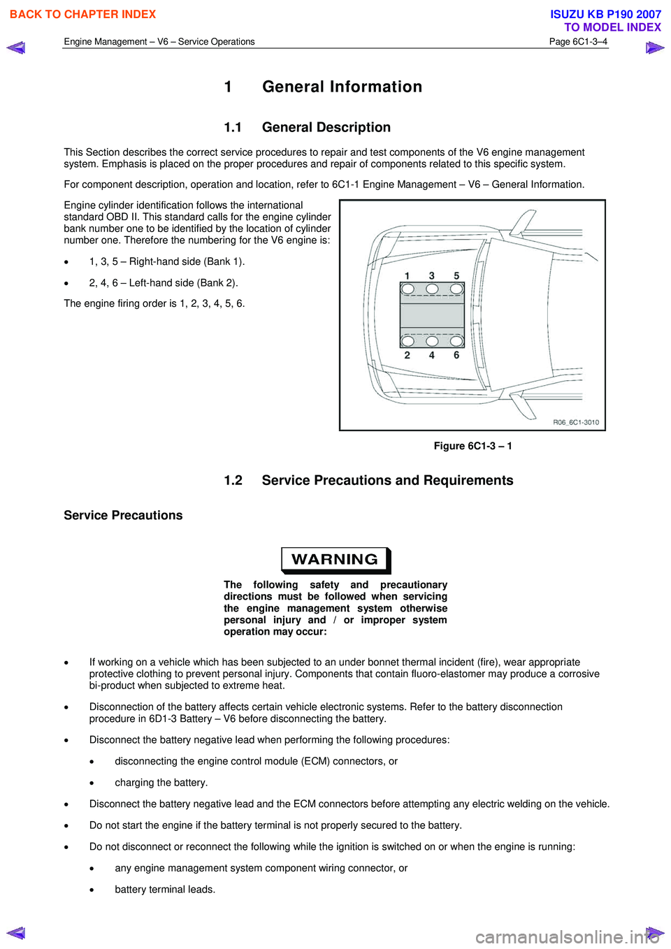
Engine cylinder identification follows the international
standard OBD II. This standard calls for the engine cylinder
bank number one to be identified by the location of cylinder
number one. Therefore the numbering for the V6 engine is:
• 1, 3, 5 – Right-hand side (Bank 1).
• 2, 4, 6 – Left-hand side (Bank 2).
The engine firing order is 1, 2, 3, 4, 5, 6.
Figure 6C1-3 – 1
1.2 Service Precautions and Requirements
Service Precautions
The following safety and precautionary
directions must be followed when servicing
the engine management system otherwise
personal injury and / or improper system
operation may occur:
• If working on a vehicle which has been subjected to an under bonnet thermal incident (fire), wear appropriate
protective clothing to prevent personal injury. Components that contain fluoro-elastomer may produce a corrosive
bi-product when subjected to extreme heat.
• Disconnection of the battery affects certain vehicle electronic systems. Refer to the battery disconnection
procedure in 6D1-3 Battery – V6 before disconnecting the battery.
• Disconnect the battery negative lead when performing the following procedures:
• disconnecting the engine control module (ECM) connectors, or
• charging the battery.
• Disconnect the battery negative lead and the ECM connectors before attempting any electric welding on the vehicle.
• Do not start the engine if the battery terminal is not properly secured to the battery.
• Do not disconnect or reconnect the following while the ignition is switched on or when the engine is running:
• any engine management system component wiring connector, or
• battery terminal leads.
BACK TO CHAPTER INDEX
TO MODEL INDEX
ISUZU KB P190 2007
Page 3533 of 6020
Engine Management – V6 – Service Operations Page 6C1-3–9
2 General Service Operations
2.1 Accelerator Pedal Position Sensor
Remove
1 Turn the ignition switch off.
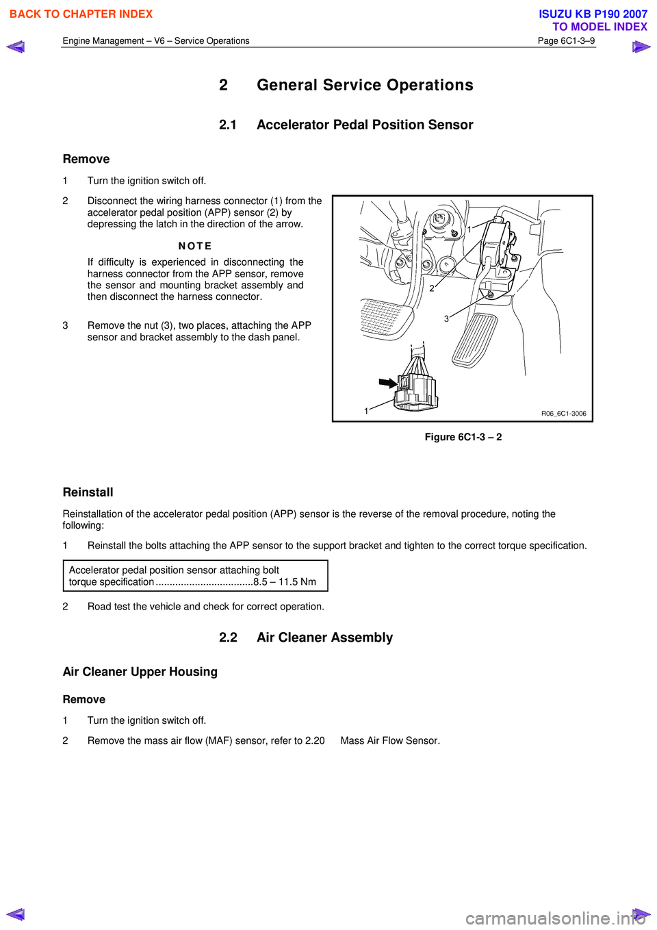
2 Disconnect the wiring harness connector (1) from the accelerator pedal position (APP) sensor (2) by
depressing the latch in the direction of the arrow.
NOTE
If difficulty is experienced in disconnecting the
harness connector from the APP sensor, remove
the sensor and mounting bracket assembly and
then disconnect the harness connector.
3 Remove the nut (3), two places, attaching the APP sensor and bracket assembly to the dash panel.
Figure 6C1-3 – 2
Reinstall
Reinstallation of the accelerator pedal position (APP) sensor is the reverse of the removal procedure, noting the
following:
1 Reinstall the bolts attaching the APP sensor to the support bracket and tighten to the correct torque specification.
Accelerator pedal position sensor attaching bolt
torque specification ...................................8.5 – 11.5 Nm
2 Road test the vehicle and check for correct operation.
2.2 Air Cleaner Assembly
Air Cleaner Upper Housing
Remove
1 Turn the ignition switch off.
2 Remove the mass air flow (MAF) sensor, refer to 2.20 Mass Air Flow Sensor.
BACK TO CHAPTER INDEX
TO MODEL INDEX
ISUZU KB P190 2007
Page 3534 of 6020
Engine Management – V6 – Service Operations Page 6C1-3–10
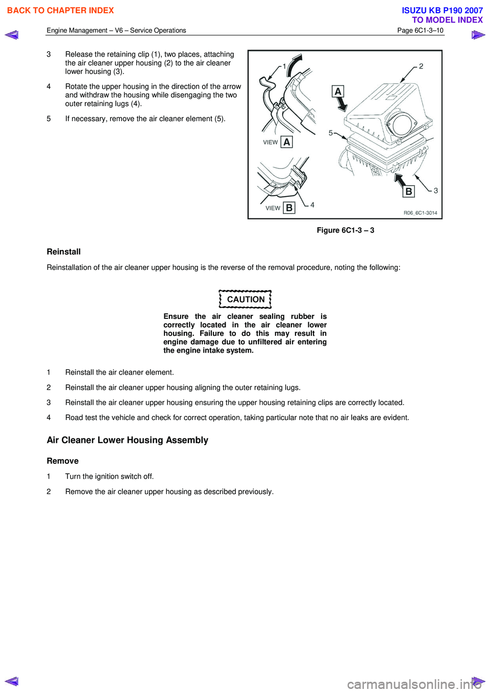
3 Release the retaining clip (1), two places, attaching
the air cleaner upper housing (2) to the air cleaner
lower housing (3).
4 Rotate the upper housing in the direction of the arrow and withdraw the housing while disengaging the two
outer retaining lugs (4).
5 If necessary, remove the air cleaner element (5).
Figure 6C1-3 – 3
Reinstall
Reinstallation of the air cleaner upper housing is the reverse of the removal procedure, noting the following:
Ensure the air cleaner sealing rubber is
correctly located in the air cleaner lower
housing. Failure to do this may result in
engine damage due to unfiltered air entering
the engine intake system.
1 Reinstall the air cleaner element.
2 Reinstall the air cleaner upper housing aligning the outer retaining lugs.
3 Reinstall the air cleaner upper housing ensuring the upper housing retaining clips are correctly located.
4 Road test the vehicle and check for correct operation, taking particular note that no air leaks are evident.
Air Cleaner Lower Housing Assembly
Remove
1 Turn the ignition switch off.
2 Remove the air cleaner upper housing as described previously.
BACK TO CHAPTER INDEX
TO MODEL INDEX
ISUZU KB P190 2007