Page 3714 of 6020
Powertrain Interface Module – V6 Page 6E1–53
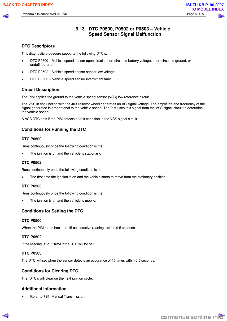
9.13 DTC P0500, P0502 or P0503 – Vehicle
Speed Sensor Signal Malfunction
DTC Descriptors
This diagnostic procedure supports the following DTC’s:
• DTC P0500 – Vehicle speed sensor open circuit, short circuit to battery voltage, short circuit to ground, or
undefined error
• DTC P0502 – Vehicle speed sensor sensor low voltage
• DTC P0503 – Vehicle speed sensor intermittant fault
Circuit Description
The PIM applies the ground to the vehicle speed sensor (VSS) low reference circuit.
The VSS in conjunction with the 40X reluctor wheel generates an AC signal voltage. The amplitude and frequency of the
signal generated is proportional to the vehicle speed. The PIM uses this signal from the VSS signal circuit to determine
the vehicle speed.
A VSS DTC sets if the PIM detects a fault condition in the VSS signal circuit.
Conditions for Running the DTC
DTC P0500
Runs continuously once the following condition is met:
• The ignition is on and the vehicle is stationary.
DTC P0502
Runs continuously once the following condition is met:
• The first time the ignition is on and the vehicle starts to move from the stationary position.
DTC P0503
Runs continuously once the following condition is met:
• The ignition is on and the vehicle is mobile.
Conditions for Setting the DTC
DTC P0500
W hen the PIM reads back the 15 consecutive readings within 0.5 seconds.
DTC P0502
If the reading is >9.1 Km/Hr the DTC will be set.
DTC P0503
The DTC will set when the sensor detects an occurance of 15 times within 0.5 seconds.
Conditions for Clearing DTC
The DTC’s will clear on the next ignition cycle.
Additional Information
• Refer to 7B1_Manual Transmission.
BACK TO CHAPTER INDEX
TO MODEL INDEX
ISUZU KB P190 2007
Page 3715 of 6020
Powertrain Interface Module – V6 Page 6E1–54
• For an intermittent fault condition, refer to Intermittent Fault Conditions in this Section.
• The VSS in conjunction with the 40X reluctor wheel generates an AC signal voltage. The amplitude and frequency
of the signal generated is proportional to the vehicle speed. The PIM uses this signal from the VSS signal circuit to
determine the vehicle speed.
• Since fault condition in a wiring connector may trigger DTCs, always test the connectors related to this diagnostic
procedure for shorted terminals or poor wiring connection before replacing any component. Refer to 8A Electrical -
Body and Chassis for information on electrical fault diagnosis.
• To assist diagnosis, refer to 6 W iring Diagram and Connector Chart in this Section, for the system wiring diagram
and connector charts.
Test Description
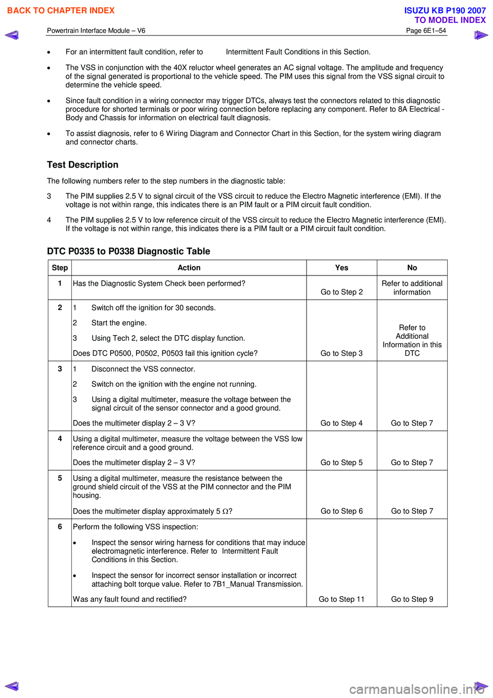
The following numbers refer to the step numbers in the diagnostic table:
3 The PIM supplies 2.5 V to signal circuit of the VSS circuit to reduce the Electro Magnetic interference (EMI). If the voltage is not within range, this indicates there is an PIM fault or a PIM circuit fault condition.
4 The PIM supplies 2.5 V to low reference circuit of the VSS circuit to reduce the Electro Magnetic interference (EMI). If the voltage is not within range, this indicates there is a PIM fault or a PIM circuit fault condition.
DTC P0335 to P0338 Diagnostic Table
Step Action Yes No
1
Has the Diagnostic System Check been performed?
Go to Step 2 Refer to additional
information
2 1 Switch off the ignition for 30 seconds.
2 Start the engine.
3 Using Tech 2, select the DTC display function.
Does DTC P0500, P0502, P0503 fail this ignition cycle? Go to Step 3 Refer to
Additional
Information in this DTC
3 1 Disconnect the VSS connector.
2 Switch on the ignition with the engine not running.
3 Using a digital multimeter, measure the voltage between the signal circuit of the sensor connector and a good ground.
Does the multimeter display 2 – 3 V? Go to Step 4 Go to Step 7
4 Using a digital multimeter, measure the voltage between the VSS low
reference circuit and a good ground.
Does the multimeter display 2 – 3 V? Go to Step 5 Go to Step 7
5 Using a digital multimeter, measure the resistance between the
ground shield circuit of the VSS at the PIM connector and the PIM
housing.
Does the multimeter display approximately 5 Ω? Go to Step 6 Go to Step 7
6
Perform the following VSS inspection:
• Inspect the sensor wiring harness for conditions that may induce
electromagnetic interference. Refer to Intermittent Fault
Conditions in this Section.
• Inspect the sensor for incorrect sensor installation or incorrect
attaching bolt torque value. Refer to 7B1_Manual Transmission.
W as any fault found and rectified? Go to Step 11 Go to Step 9
BACK TO CHAPTER INDEX
TO MODEL INDEX
ISUZU KB P190 2007
Page 3734 of 6020
Powertrain Interface Module – V6 Page 6E1–73
11.3 Vertical Acceleration Sensor
Remove
1 Turn the ignition switch off.
2 Using a hoist raise the vehicle to a suitable working height.
3 Remove the VAS connector.
4 Remove the nut (1) securing the VAS to the mounting bracket.
5 Remove the VAS (2) from the mounting bracket.
Figure 6E1 – 17
Reinstall
Reinstallation of the VAS is the reverse of the removal procedure, noting the following:
1 Tighten the attaching nut to the correct torque specification.
VAS attaching nut
torque specification .................................12.0 – 16.0 Nm
2 Check the system for correct operation, refer to 7.2 Diagnostic System Check.
3 Road test the vehicle and check for correct vehicle operation.
BACK TO CHAPTER INDEX
TO MODEL INDEX
ISUZU KB P190 2007
Page 3742 of 6020
Powertrain Interface Module – V6 Page 6E1–81
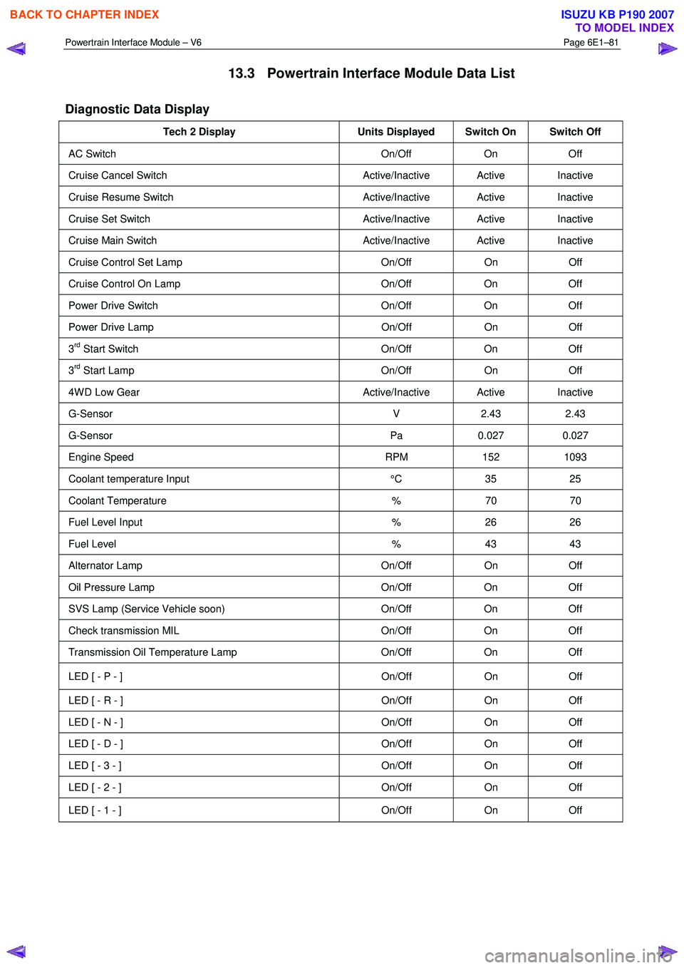
13.3 Powertrain Interface Module Data List
Diagnostic Data Display
Tech 2 Display Units Displayed Switch On Switch Off
AC Switch On/Off On Off
Cruise Cancel Switch Active/Inactive Active Inactive
Cruise Resume Switch Active/Inactive Active Inactive
Cruise Set Switch Active/Inactive Active Inactive
Cruise Main Switch Active/Inactive Active Inactive
Cruise Control Set Lamp On/Off On Off
Cruise Control On Lamp On/Off On Off
Power Drive Switch On/Off On Off
Power Drive Lamp On/Off On Off
3rd Start Switch On/Off On Off
3rd Start Lamp On/Off On Off
4W D Low Gear Active/Inactive Active Inactive
G-Sensor V 2.43 2.43
G-Sensor Pa 0.027 0.027
Engine Speed RPM 152 1093
Coolant temperature Input °C 35 25
Coolant Temperature % 70 70
Fuel Level Input % 26 26
Fuel Level % 43 43
Alternator Lamp On/Off On Off
Oil Pressure Lamp On/Off On Off
SVS Lamp (Service Vehicle soon) On/Off On Off
Check transmission MIL On/Off On Off
Transmission Oil Temperature Lamp On/Off On Off
LED [ - P - ] On/Off On Off
LED [ - R - ] On/Off On Off
LED [ - N - ] On/Off On Off
LED [ - D - ] On/Off On Off
LED [ - 3 - ] On/Off On Off
LED [ - 2 - ] On/Off On Off
LED [ - 1 - ] On/Off On Off
BACK TO CHAPTER INDEX
TO MODEL INDEX
ISUZU KB P190 2007
Page 3747 of 6020
Powertrain Interface Module – V6 Page 6E1–86
15 Torque Wrench Specifications
Powertrain Interface Module Attaching Screw ............................. 8.0 – 12.0 Nm
Vertical Acceleration Sensor attaching nut ............................... 12.0 – 16.0 Nm
BACK TO CHAPTER INDEX
TO MODEL INDEX
ISUZU KB P190 2007
Page 3755 of 6020
Exhaust System – V6 Page 6F – 7
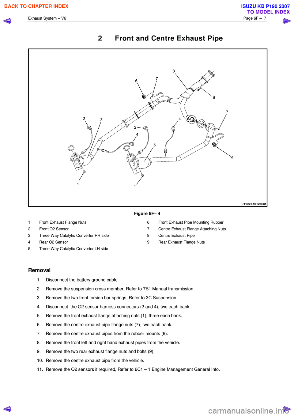
2 Front and Centre Exhaust Pipe
Figure 6F– 4
1 Front Exhaust Flange Nuts
2 Front O2 Sensor
3 Three Way Catalytic Converter RH side
4 Rear O2 Sensor
5 Three Way Catalytic Converter LH side 6 Front Exhaust Pipe Mounting Rubber
7 Centre Exhaust Flange Attaching Nuts
8 Centre Exhaust Pipe
9 Rear Exhaust Flange Nuts
Removal
1. Disconnect the battery ground cable.
2. Remove the suspension cross member, Refer to 7B1 Manual transmission.
3. Remove the two front torsion bar springs, Refer to 3C Suspension.
4. Disconnect the O2 sensor harness connectors (2 and 4), two each bank.
5. Remove the front exhaust flange attaching nuts (1), three each bank.
6. Remove the centre exhaust pipe flange nuts (7), two each bank.
7. Remove the centre exhaust pipes from the rubber mounts (6).
8. Remove the front left and right hand exhaust pipes from the vehicle.
9. Remove the two rear exhaust flange nuts and bolts (9).
10. Remove the centre exhaust pipe from the vehicle.
11. Remove the O2 sensors if required, Refer to 6C1 – 1 Engine Management General Info.
BACK TO CHAPTER INDEX
TO MODEL INDEX
ISUZU KB P190 2007
Page 3756 of 6020
Exhaust System – V6 Page 6F – 8
NOTE:
• Support the exhaust system at all times.
• Clean the threads of the attaching bolts, nuts,
studs and flanges with a suitable cleaning
solvent.
• Apply a high temperature anti-seize
compound to the manifold front pipe flange
joint studs, then align the flange over the
studs.
Reinstallation
1. Install any removed O2 sensors, Refer to 6C1 – 1 Engine Management General Info.
2. Position the centre exhaust pipe into location under the vehicle.
3. Install the two rear exhaust flange nuts and bolts (9).
4. Position the front exhaust pipes into location under the vehicle.
5. Install the centre exhaust pipes into the rubber mounts (6).
6. Install the exhaust flange fixing nuts (1), three each bank.
7. Install the rear exhaust pipe flange nuts (7), two each bank.
8. Reconnect the O2 sensor harness connectors (4), two each bank.
9. Install the two front torsion bar springs, Refer to 3C Suspension.
10. Install the suspension cross member, Refer to 7B1 Manual transmission.
11. Reconnect the battery ground cable.
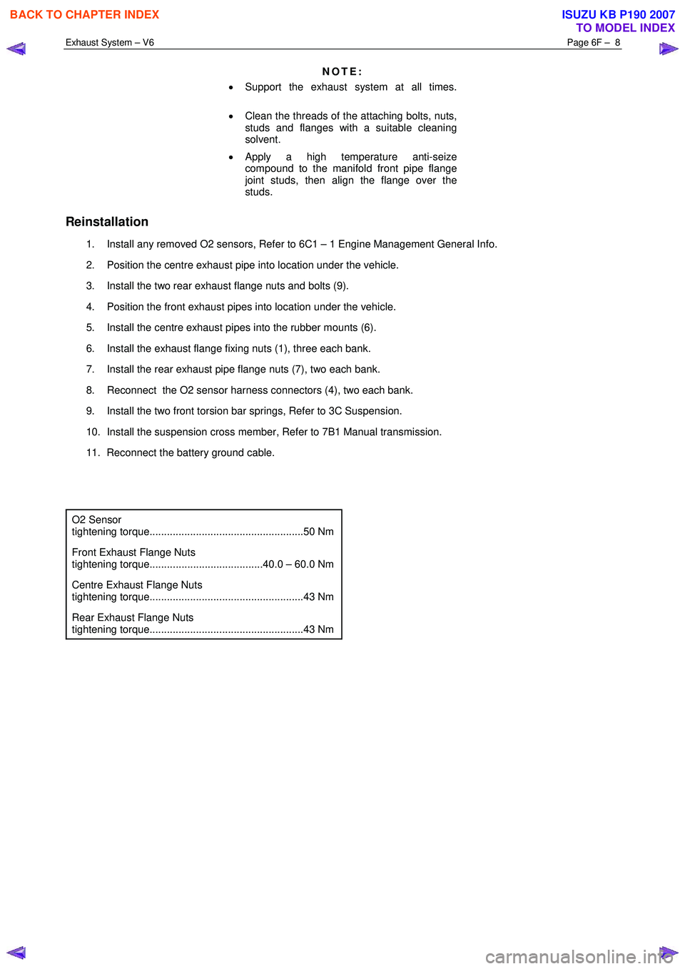
O2 Sensor
tightening torque.....................................................50 Nm
Front Exhaust Flange Nuts
tightening torque.......................................40.0 – 60.0 Nm
Centre Exhaust Flange Nuts
tightening torque.....................................................43 Nm
Rear Exhaust Flange Nuts
tightening torque.....................................................43 Nm
BACK TO CHAPTER INDEX
TO MODEL INDEX
ISUZU KB P190 2007
Page 3758 of 6020
Exhaust System – V6 Page 6F – 10
4 Torque Wrench Specifications
..................................................................................................................... Nm
Front Exhaust Flange Nuts...............................................................40.0 – 60.0
Centre Exhaust Flange Nuts .......................................................................43.0
Rear Exhaust Flange Nuts ..........................................................................43.0
O2 Sensor ...................................................................................................50.0
BACK TO CHAPTER INDEX
TO MODEL INDEX
ISUZU KB P190 2007