2007 ISUZU KB P190 sensor
[x] Cancel search: sensorPage 3647 of 6020
Battery Page 6D1-3–7
3 Diagnosis
3.1 Diagnostic Procedures
Introduction
This test is used to aid in diagnosing faults with the vehicle where the battery seems to be at fault.
W ith the increased use of electronic sensors and computer control, the battery is much more than just a component used
to start a car. Low battery voltage can:
• affect the operation of the vehicle control modules and cause driveability problems, and
• cause the control modules to set diagnostic trouble codes (DTCs).
For example if a control module senses low battery voltage, it may increase fuel injector timing to increase engine rpm to
increase the generator output.
Therefore consider the state of charge of the battery any time a customer complains of a driveability related problem.
Test Description
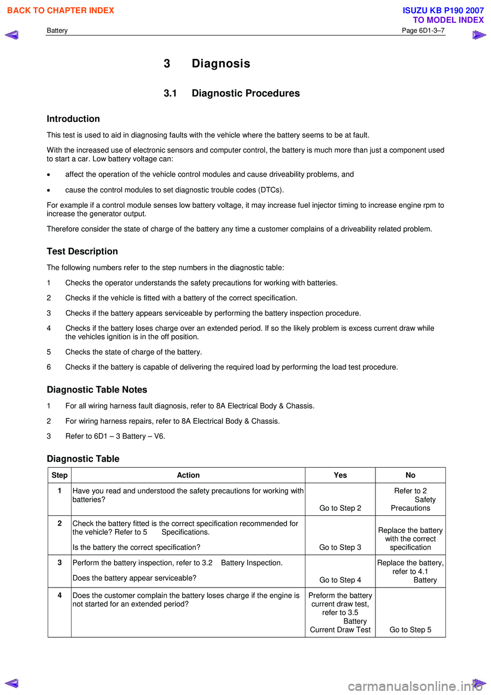
The following numbers refer to the step numbers in the diagnostic table:
1 Checks the operator understands the safety precautions for working with batteries.
2 Checks if the vehicle is fitted with a battery of the correct specification.
3 Checks if the battery appears serviceable by performing the battery inspection procedure.
4 Checks if the battery loses charge over an extended period. If so the likely problem is excess current draw while the vehicles ignition is in the off position.
5 Checks the state of charge of the battery.
6 Checks if the battery is capable of delivering the required load by performing the load test procedure.
Diagnostic Table Notes
1 For all wiring harness fault diagnosis, refer to 8A Electrical Body & Chassis.
2 For wiring harness repairs, refer to 8A Electrical Body & Chassis.
3 Refer to 6D1 – 3 Battery – V6.
Diagnostic Table
Step Action Yes No
1
Have you read and understood the safety precautions for working with
batteries? Go to Step 2 Refer to 2
Safety Precautions
2 Check the battery fitted is the correct specification recommended for
the vehicle? Refer to 5 Specifications.
Is the battery the correct specification? Go to Step 3 Replace the battery
with the correct
specification
3 Perform the battery inspection, refer to 3.2 Battery Inspection.
Does the battery appear serviceable? Go to Step 4 Replace the battery,
refer to 4.1
Battery
4 Does the customer complain the battery loses charge if the engine is
not started for an extended period? Preform the battery
current draw test, refer to 3.5
Battery
Current Draw Test Go to Step 5
BACK TO CHAPTER INDEX
TO MODEL INDEX
ISUZU KB P190 2007
Page 3664 of 6020
Powertrain Interface Module – V6 Page 6E1–3
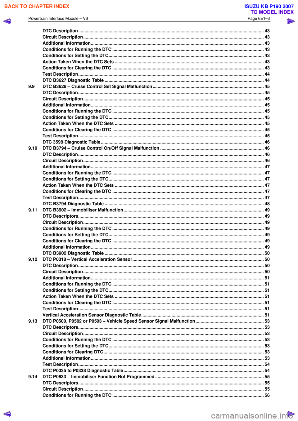
DTC Description ................................................................................................................................................... 43
Circuit Description ............................................................................................................................................... 43
Additional Information......................................................................................................... ................................ 43
Conditions for Running the DTC ................................................................................................. ....................... 43
Conditions for Setting the DTC........................................................................................................................... 43
Action Taken When the DTC Sets ................................................................................................. ..................... 43
Conditions for Clearing the DTC ........................................................................................................................ 43
Test Description ................................................................................................................................................... 44
DTC B3627 Diagnostic Table ..................................................................................................... ......................... 44
9.9 DTC B3628 – Cruise Control Set Signal Malfunction .............................................................................. .......... 45
DTC Description ................................................................................................................................................... 45
Circuit Description ............................................................................................................................................... 45
Additional Information......................................................................................................... ................................ 45
Conditions for Running the DTC ................................................................................................. ....................... 45
Conditions for Setting the DTC........................................................................................................................... 45
Action Taken When the DTC Sets ................................................................................................. ..................... 45
Conditions for Clearing the DTC ........................................................................................................................ 45
Test Description ................................................................................................................................................... 45
DTC 3598 Diagnostic Table ...................................................................................................... ........................... 46
9.10 DTC B3794 – Cruise Control On/Off Signal Malfunction ........................................................................... ....... 46
DTC Description ................................................................................................................................................... 46
Circuit Description ............................................................................................................................................... 46
Additional Information......................................................................................................... ................................ 47
Conditions for Running the DTC ................................................................................................. ....................... 47
Conditions for Setting the DTC........................................................................................................................... 47
Action Taken When the DTC Sets ................................................................................................. ..................... 47
Conditions for Clearing the DTC ........................................................................................................................ 47
Test Description ................................................................................................................................................... 47
DTC B3794 Diagnostic Table ..................................................................................................... ......................... 48
9.11 DTC B3902 – Immobiliser Malfunction ............................................................................................ ................... 49
DTC Descriptors................................................................................................................................................... 49
Circuit Description ............................................................................................................................................... 49
Conditions for Running the DTC ................................................................................................. ....................... 49
Conditions for Setting the DTC........................................................................................................................... 49
Conditions for Clearing the DTC ................................................................................................ ........................ 49
Additional Information......................................................................................................................................... 49
DTC B3902 Diagnostic Table ..................................................................................................... ......................... 50
9.12 DTC P0318 – Vertical Acceleration Sensor....................................................................................... ................. 50
DTC Description ................................................................................................................................................... 50
Circuit Description ............................................................................................................................................... 50
Additional Information......................................................................................................... ................................ 51
Conditions for Running the DTC ................................................................................................. ....................... 51
Conditions for Setting the DTC........................................................................................................................... 51
Action Taken When the DTC Sets ................................................................................................. ..................... 51
Conditions for Clearing the DTC ........................................................................................................................ 51
Test Description ................................................................................................................................................... 51
Vertical Acceleration Sensor Diagnostic Table .................................................................................. ............... 51
9.13 DTC P0500, P0502 or P0503 – Vehicle Speed Sensor Signal Malfunction ...................................................... 53
DTC Descriptors................................................................................................................................................... 53
Circuit Description ............................................................................................................................................... 53
Conditions for Running the DTC ................................................................................................. ....................... 53
Conditions for Setting the DTC........................................................................................................................... 53
Conditions for Clearing DTC ............................................................................................................................... 53
Additional Information......................................................................................................................................... 53
Test Description ................................................................................................................................................... 54
DTC P0335 to P0338 Diagnostic Table ............................................................................................ ................... 54
9.14 DTC P0633 – Immobiliser Function Not Programmed ................................................................................ ...... 55
DTC Descriptors................................................................................................................................................... 55
Circuit Description ............................................................................................................................................... 55
Conditions for Running the DTC ................................................................................................. ....................... 56
BACK TO CHAPTER INDEX
TO MODEL INDEX
ISUZU KB P190 2007
Page 3665 of 6020
Powertrain Interface Module – V6 Page 6E1–4
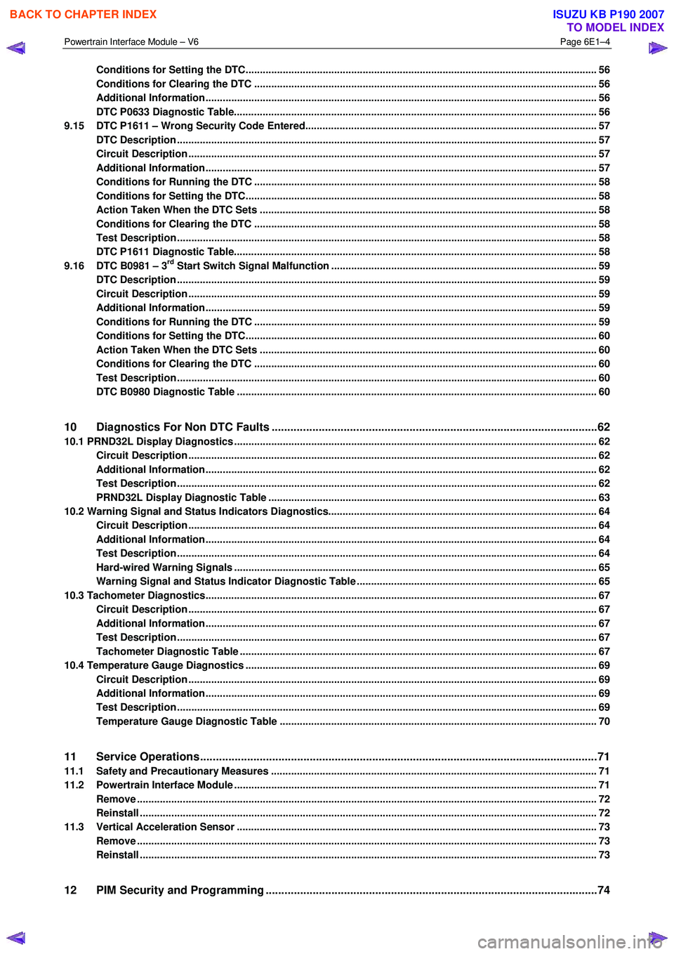
Conditions for Setting the DTC........................................................................................................................... 56
Conditions for Clearing the DTC ................................................................................................ ........................ 56
Additional Information......................................................................................................................................... 56
DTC P0633 Diagnostic Table..................................................................................................... .......................... 56
9.15 DTC P1611 – Wrong Security Code Entered........................................................................................ .............. 57
DTC Description ................................................................................................................................................... 57
Circuit Description ............................................................................................................................................... 57
Additional Information......................................................................................................... ................................ 57
Conditions for Running the DTC ................................................................................................. ....................... 58
Conditions for Setting the DTC........................................................................................................................... 58
Action Taken When the DTC Sets ................................................................................................. ..................... 58
Conditions for Clearing the DTC ........................................................................................................................ 58
Test Description ................................................................................................................................................... 58
DTC P1611 Diagnostic Table..................................................................................................... .......................... 58
9.16 DTC B0981 – 3rd Start Switch Signal Malfunction ............................................................................................. 59
DTC Description ................................................................................................................................................... 59
Circuit Description ............................................................................................................................................... 59
Additional Information......................................................................................................... ................................ 59
Conditions for Running the DTC ................................................................................................. ....................... 59
Conditions for Setting the DTC........................................................................................................................... 60
Action Taken When the DTC Sets ................................................................................................. ..................... 60
Conditions for Clearing the DTC ........................................................................................................................ 60
Test Description ................................................................................................................................................... 60
DTC B0980 Diagnostic Table ..................................................................................................... ......................... 60
10 Diagnostics For Non DTC Faults ................................................................................................. .......62
10.1 PRND32L Display Diagnostics ............................................................................................... ................................ 62
Circuit Description ............................................................................................................................................... 62
Additional Information......................................................................................................... ................................ 62
Test Description ................................................................................................................................................... 62
PRND32L Display Diagnostic Table ............................................................................................... .................... 63
10.2 Warning Signal and Status Indicators Diagnostics.......................................................................... .................... 64
Circuit Description ............................................................................................................................................... 64
Additional Information......................................................................................................... ................................ 64
Test Description ................................................................................................................................................... 64
Hard-wired Warning Signals ..................................................................................................... .......................... 65
Warning Signal and Status Indicator Diagnostic Table ........................................................................... ......... 65
10.3 Tachometer Diagnostics......................................................................................................................................... 67
Circuit Description ............................................................................................................................................... 67
Additional Information......................................................................................................... ................................ 67
Test Description ................................................................................................................................................... 67
Tachometer Diagnostic Table .................................................................................................... ......................... 67
10.4 Temperature Gauge Diagnostics ............................................................................................. .............................. 69
Circuit Description ............................................................................................................................................... 69
Additional Information......................................................................................................... ................................ 69
Test Description ................................................................................................................................................... 69
Temperature Gauge Diagnostic Table ............................................................................................. .................. 70
11 Service Operations ...............................................................................................................................71
11.1 Safety and Precautionary Measures .................................................................................................................. 71
11.2 Powertrain Interface Module ............................................................................................................................... 71
Remove ................................................................................................................................................................. 72
Reinstall ................................................................................................................................................................ 72
11.3 Vertical Acceleration Sensor ................................................................................................... ........................... 73
Remove ................................................................................................................................................................. 73
Reinstall ................................................................................................................................................................ 73
12 PIM Security and Programming ................................................................................................... .......74
BACK TO CHAPTER INDEX
TO MODEL INDEX
ISUZU KB P190 2007
Page 3671 of 6020
Powertrain Interface Module – V6 Page 6E1–10
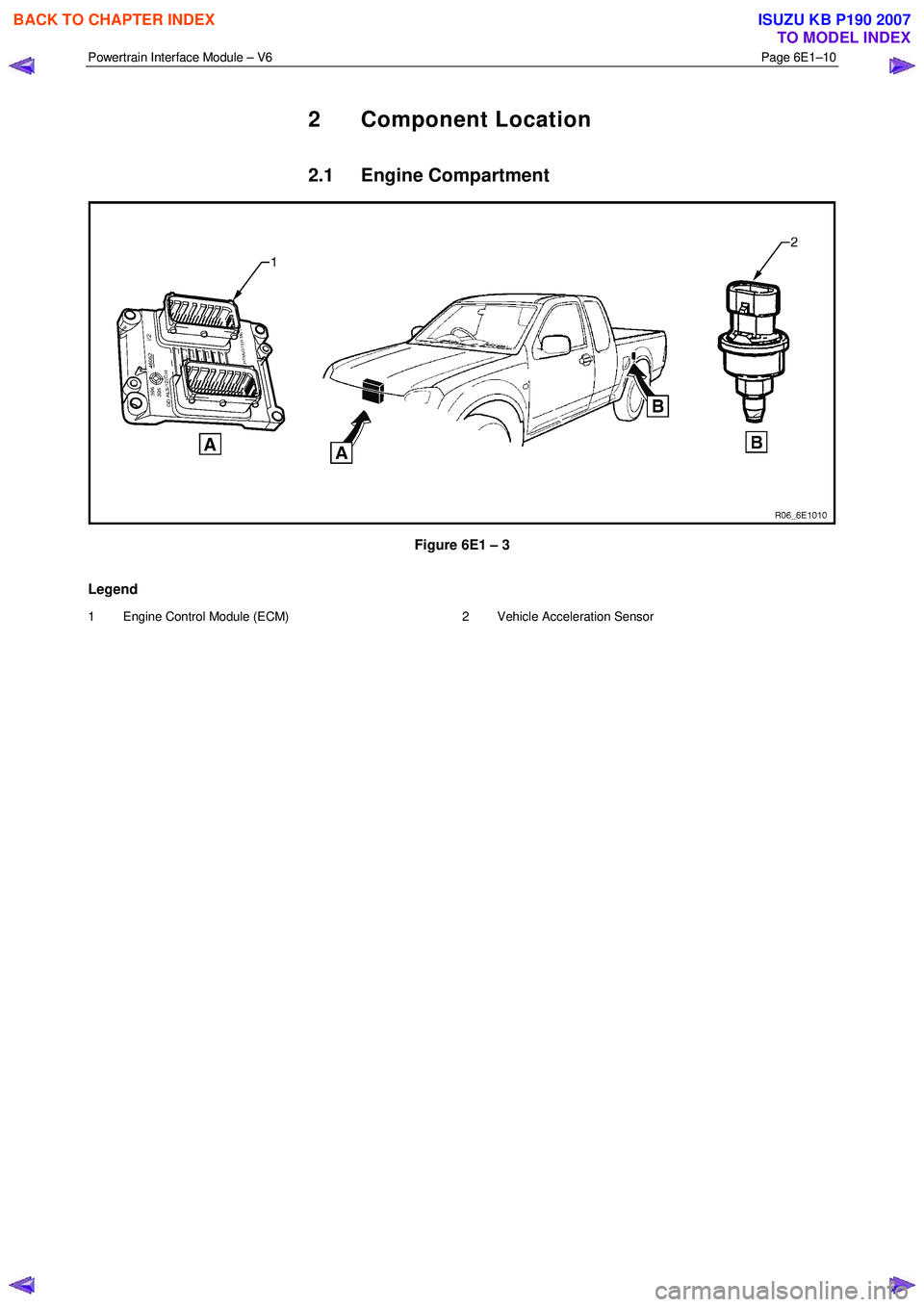
2 Component Location
2.1 Engine Compartment
Figure 6E1 – 3
Legend
1 Engine Control Module (ECM) 2 Vehicle Acceleration Sensor
BACK TO CHAPTER INDEX
TO MODEL INDEX
ISUZU KB P190 2007
Page 3683 of 6020
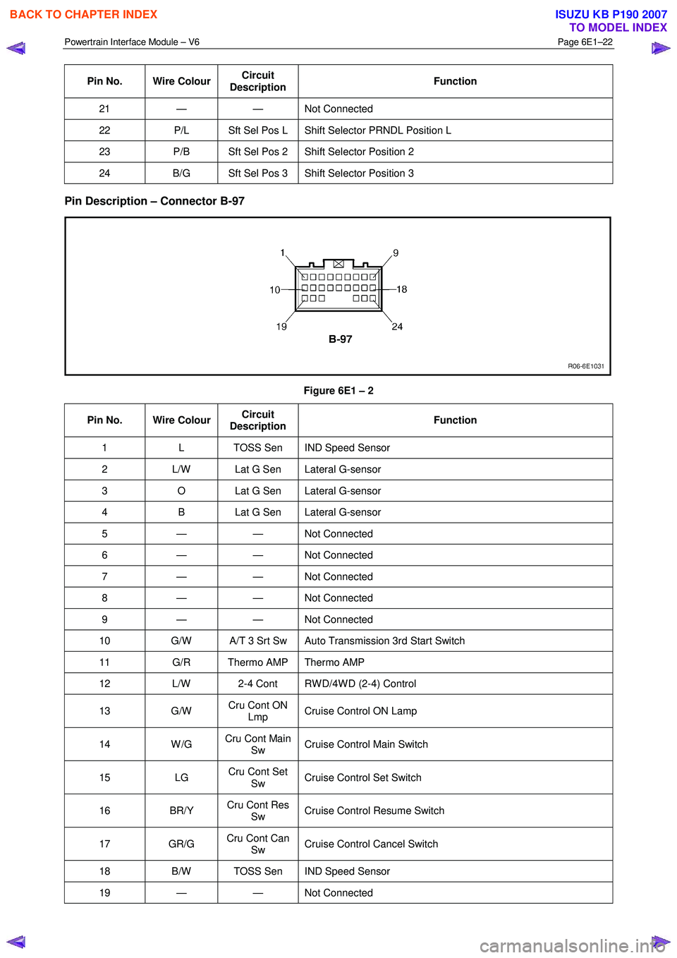
Powertrain Interface Module – V6 Page 6E1–22
Pin No. Wire Colour Circuit
Description Function
21 — — Not
Connected
22 P/L Sft Sel Pos L Shift Selector PRNDL Position L
23 P/B Sft Sel Pos 2 Shift Selector Position 2
24 B/G Sft Sel Pos 3 Shift Selector Position 3
Pin Description – Connector B-97
Figure 6E1 – 2
Pin No. Wire Colour Circuit
Description Function
1
L TOSS Sen IND Speed Sensor
2 L/W Lat G Sen Lateral G-sensor
3 O Lat G Sen Lateral G-sensor
4 B Lat G Sen Lateral G-sensor
5 — — Not Connected
6 — — Not Connected
7 — — Not Connected
8 — — Not Connected
9 — — Not Connected
10 G/W A/T 3 Srt Sw Auto Transmission 3rd Start Switch
11 G/R Thermo AMP Thermo AMP
12 L/W 2-4 Cont RW D/4W D (2-4) Control
13 G/W Cru Cont ON
Lmp Cruise Control ON Lamp
14 W /G
Cru Cont Main
Sw Cruise Control Main Switch
15 LG Cru Cont Set
Sw Cruise Control Set Switch
16 BR/Y
Cru Cont Res
Sw Cruise Control Resume Switch
17 GR/G
Cru Cont Can
Sw Cruise Control Cancel Switch
18
B/W TOSS Sen IND Speed Sensor
19 — — Not Connected
BACK TO CHAPTER INDEX
TO MODEL INDEX
ISUZU KB P190 2007
Page 3711 of 6020
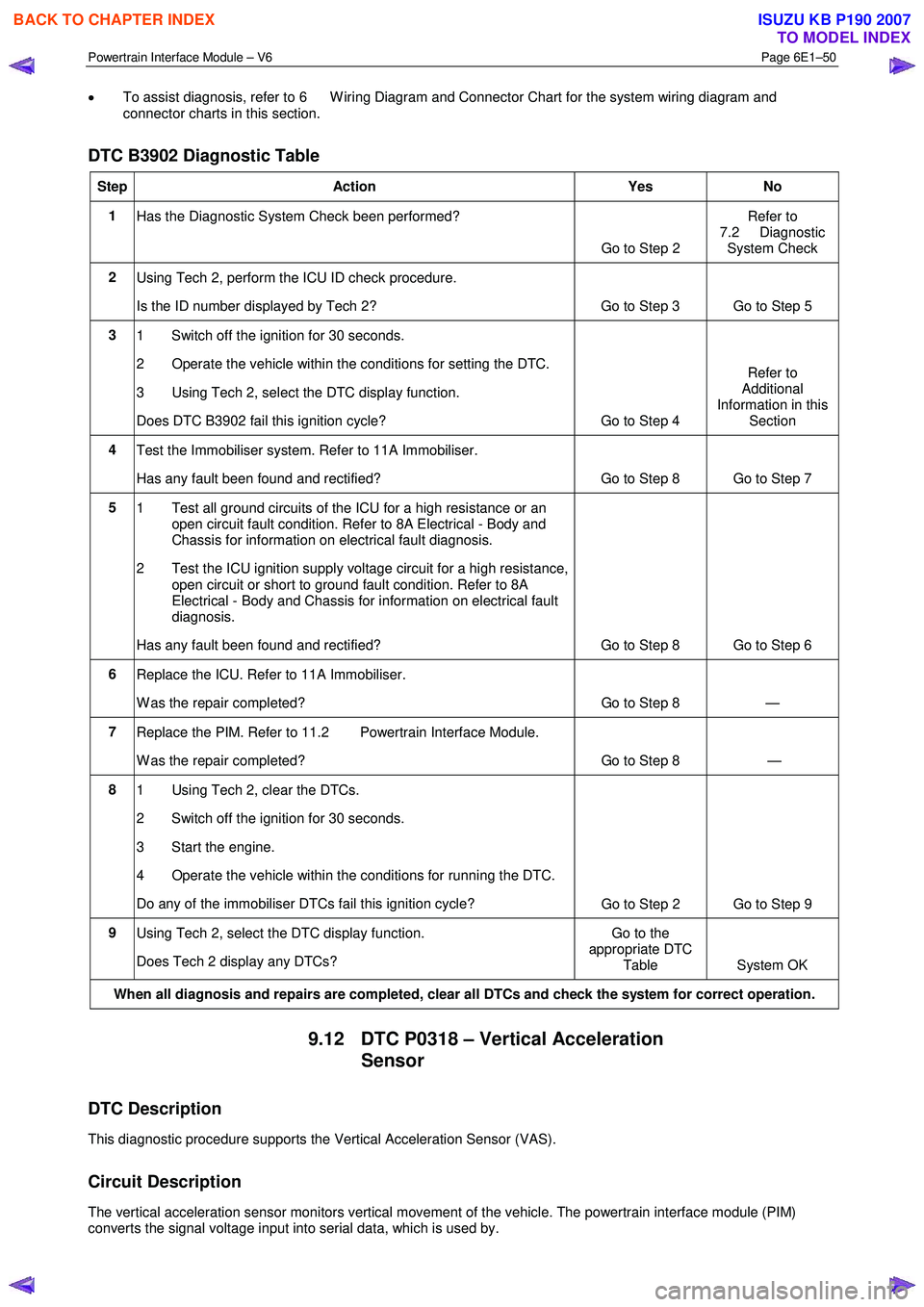
Powertrain Interface Module – V6 Page 6E1–50
• To assist diagnosis, refer to 6 W iring Diagram and Connector Chart for the system wiring diagram and
connector charts in this section.
DTC B3902 Diagnostic Table
Step Action Yes No
1
Has the Diagnostic System Check been performed?
Go to Step 2 Refer to
7.2 Diagnostic System Check
2 Using Tech 2, perform the ICU ID check procedure.
Is the ID number displayed by Tech 2? Go to Step 3
Go to Step 5
3 1 Switch off the ignition for 30 seconds.
2 Operate the vehicle within the conditions for setting the DTC.
3 Using Tech 2, select the DTC display function.
Does DTC B3902 fail this ignition cycle? Go to Step 4 Refer to
Additional
Information in this Section
4 Test the Immobiliser system. Refer to 11A Immobiliser.
Has any fault been found and rectified? Go to Step 8 Go to Step 7
5 1 Test all ground circuits of the ICU for a high resistance or an
open circuit fault condition. Refer to 8A Electrical - Body and
Chassis for information on electrical fault diagnosis.
2 Test the ICU ignition supply voltage circuit for a high resistance, open circuit or short to ground fault condition. Refer to 8A
Electrical - Body and Chassis for information on electrical fault
diagnosis.
Has any fault been found and rectified? Go to Step 8 Go to Step 6
6 Replace the ICU. Refer to 11A Immobiliser.
W as the repair completed? Go to Step 8 —
7 Replace the PIM. Refer to 11.2 Powertrain Interface Module.
W as the repair completed? Go to Step 8 —
8 1 Using Tech 2, clear the DTCs.
2 Switch off the ignition for 30 seconds.
3 Start the engine.
4 Operate the vehicle within the conditions for running the DTC.
Do any of the immobiliser DTCs fail this ignition cycle? Go to Step 2 Go to Step 9
9
Using Tech 2, select the DTC display function.
Does Tech 2 display any DTCs? Go to the
appropriate DTC Table System OK
When all diagnosis and repairs are completed, clear all DTCs and check the system for correct operation.
9.12 DTC P0318 – Vertical Acceleration
Sensor
DTC Description
This diagnostic procedure supports the Vertical Acceleration Sensor (VAS).
Circuit Description
The vertical acceleration sensor monitors vertical movement of the vehicle. The powertrain interface module (PIM)
converts the signal voltage input into serial data, which is used by.
BACK TO CHAPTER INDEX
TO MODEL INDEX
ISUZU KB P190 2007
Page 3712 of 6020
Powertrain Interface Module – V6 Page 6E1–51
Additional Information
• Refer to 6 W iring Diagram and Connector Chart for the following information:
• PIM connector illustration and terminal assignment, and
• PIM wiring diagram.
• For intermittent fault conditions, refer to Intermittent Fault Conditions.
• Since fault conditions in a wiring connector may trigger DTCs, always test the connectors related to this diagnostic
procedure for shorted terminals or poor wiring connection before replacing any component. Refer to
8A Electrical - Body and Chassis for information on electrical fault diagnosis.
Conditions for Running the DTC
Conditions for running the DTC are:
• The ignition is switched on.
• The ignition voltage is 10.0 – 16.0 V.
Conditions for Setting the DTC
The DTC will set when the PIM detects a low voltage of <0.41 volts for one second.
The DTC will set when the PIM detects a high voltage of >4.59 volts for one second.
Action Taken When the DTC Sets
W hen the DTC sets, there is no warning lamp displayed on the instrument cluster.
Conditions for Clearing the DTC
The DTC is cleared at the next ignition cycle.
Refer to 4.1 Diagnostic General Descriptions for information on the conditions for clearing DTCs.
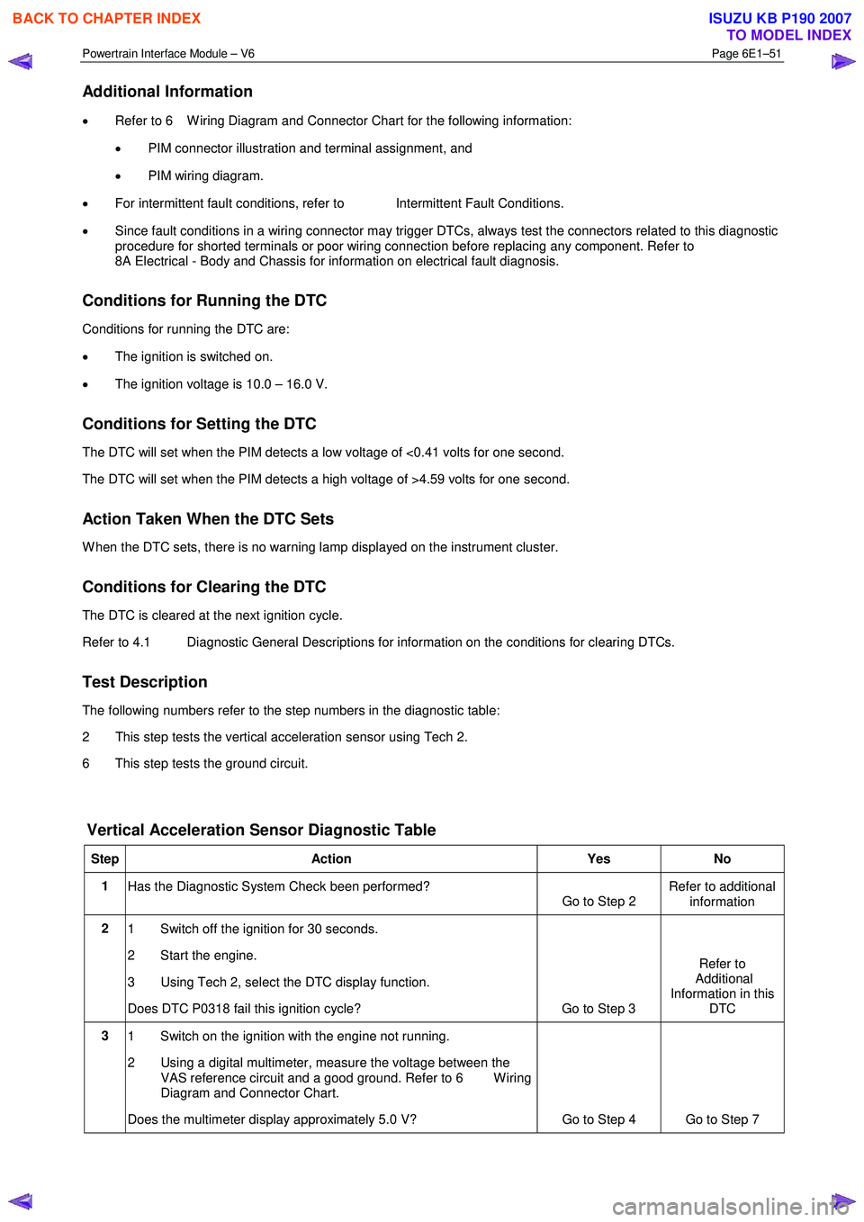
Test Description
The following numbers refer to the step numbers in the diagnostic table:
2 This step tests the vertical acceleration sensor using Tech 2.
6 This step tests the ground circuit.
Vertical Acceleration Sensor Diagnostic Table
Step Action Yes No
1
Has the Diagnostic System Check been performed?
Go to Step 2 Refer to additional
information
2 1 Switch off the ignition for 30 seconds.
2 Start the engine.
3 Using Tech 2, select the DTC display function.
Does DTC P0318 fail this ignition cycle? Go to Step 3 Refer to
Additional
Information in this DTC
3 1 Switch on the ignition with the engine not running.
2 Using a digital multimeter, measure the voltage between the VAS reference circuit and a good ground. Refer to 6 W iring
Diagram and Connector Chart.
Does the multimeter display approximately 5.0 V? Go to Step 4 Go to Step 7
BACK TO CHAPTER INDEX
TO MODEL INDEX
ISUZU KB P190 2007
Page 3713 of 6020
Powertrain Interface Module – V6 Page 6E1–52
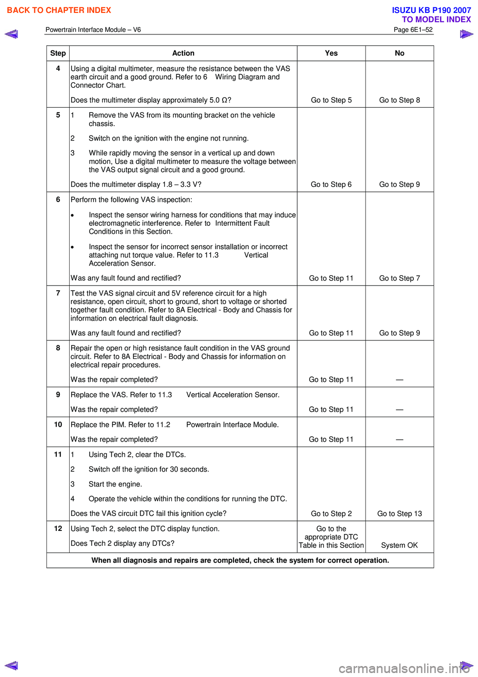
Step Action Yes No
4
Using a digital multimeter, measure the resistance between the VAS
earth circuit and a good ground. Refer to 6 W iring Diagram and
Connector Chart.
Does the multimeter display approximately 5.0 Ω?
Go to Step 5 Go to Step 8
5
1 Remove the VAS from its mounting bracket on the vehicle
chassis.
2 Switch on the ignition with the engine not running.
3 W hile rapidly moving the sensor in a vertical up and down motion, Use a digital multimeter to measure the voltage between
the VAS output signal circuit and a good ground.
Does the multimeter display 1.8 – 3.3 V? Go to Step 6 Go to Step 9
6 Perform the following VAS inspection:
• Inspect the sensor wiring harness for conditions that may induce
electromagnetic interference. Refer to Intermittent Fault
Conditions in this Section.
• Inspect the sensor for incorrect sensor installation or incorrect
attaching nut torque value. Refer to 11.3 Vertical
Acceleration Sensor.
W as any fault found and rectified? Go to Step 11 Go to Step 7
7
Test the VAS signal circuit and 5V reference circuit for a high
resistance, open circuit, short to ground, short to voltage or shorted
together fault condition. Refer to 8A Electrical - Body and Chassis for
information on electrical fault diagnosis.
W as any fault found and rectified? Go to Step 11 Go to Step 9
8
Repair the open or high resistance fault condition in the VAS ground
circuit. Refer to 8A Electrical - Body and Chassis for information on
electrical repair procedures.
W as the repair completed? Go to Step 11 —
9 Replace the VAS. Refer to 11.3 Vertical Acceleration Sensor.
W as the repair completed? Go to Step 11 —
10 Replace the PIM. Refer to 11.2 Powertrain Interface Module.
W as the repair completed? Go to Step 11 —
11 1 Using Tech 2, clear the DTCs.
2 Switch off the ignition for 30 seconds.
3 Start the engine.
4 Operate the vehicle within the conditions for running the DTC.
Does the VAS circuit DTC fail this ignition cycle? Go to Step 2 Go to Step 13
12
Using Tech 2, select the DTC display function.
Does Tech 2 display any DTCs? Go to the
appropriate DTC
Table in this Section System OK
When all diagnosis and repairs are completed, check the system for correct operation.
BACK TO CHAPTER INDEX
TO MODEL INDEX
ISUZU KB P190 2007