Page 3582 of 6020

Engine Management – V6 – Service Operations Page 6C1-3–58
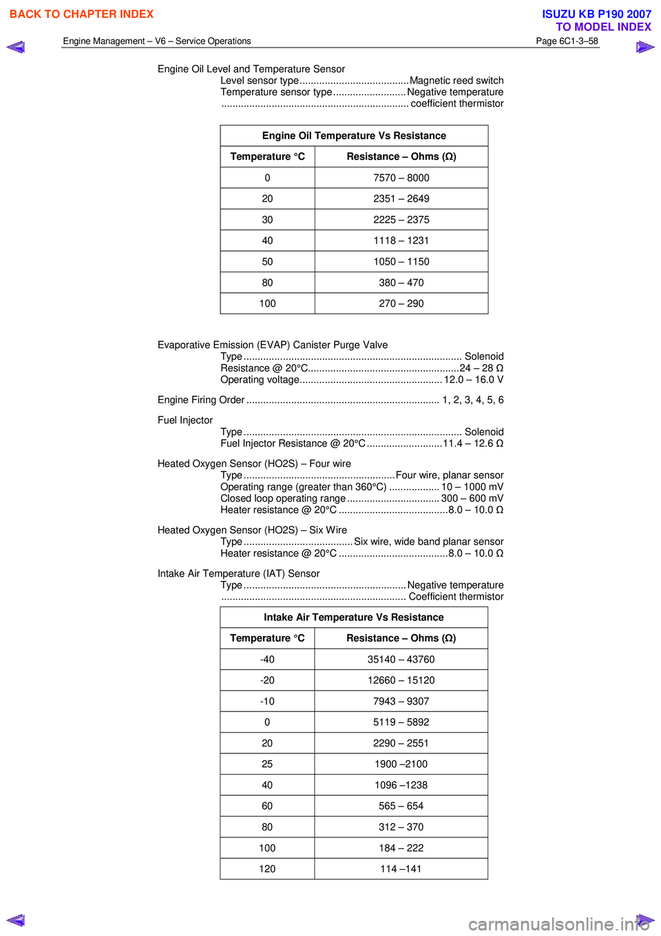
Engine Oil Level and Temperature Sensor
Level sensor type ....................................... Magnetic reed switch
Temperature sensor type .......................... Negative temperature
................................................................... coefficient thermistor
Engine Oil Temperature Vs Resistance
Temperature °C Resistance – Ohms ( Ω)
0 7570 – 8000
20 2351 – 2649
30 2225 – 2375
40 1118 – 1231
50 1050 – 1150
80 380 – 470
100 270 – 290
Evaporative Emission (EVAP) Canister Purge Valve
Type .............................................................................. Solenoid
Resistance @ 20°C...................................................... 24 – 28 Ω
Operating voltage................................................... 12.0 – 16.0 V
Engine Firing Order ..................................................................... 1, 2, 3, 4, 5, 6
Fuel Injector
Type .............................................................................. Solenoid
Fuel Injector Resistance @ 20°C ........................... 11.4 – 12.6 Ω
Heated Oxygen Sensor (HO2S) – Four wire
Type ...................................................... Four wire, planar sensor
Operating range (greater than 360°C) .................. 10 – 1000 mV
Closed loop operating range ................................. 300 – 600 mV
Heater resistance @ 20°C ....................................... 8.0 – 10.0 Ω
Heated Oxygen Sensor (HO2S) – Six W ire
Type ....................................... Six wire, wide band planar sensor
Heater resistance @ 20°C ....................................... 8.0 – 10.0 Ω
Intake Air Temperature (IAT) Sensor
Type .......................................................... Negative temperature
.................................................................. Coefficient thermistor
Intake Air Temperature Vs Resistance
Temperature °C Resistance – Ohms ( Ω)
-40 35140 – 43760
-20 12660 – 15120
-10 7943 – 9307
0 5119 – 5892
20 2290 – 2551
25 1900 –2100
40 1096 –1238
60 565 – 654
80 312 – 370
100 184 – 222
120 114 –141
BACK TO CHAPTER INDEX
TO MODEL INDEX
ISUZU KB P190 2007
Page 3583 of 6020

Engine Management – V6 – Service Operations Page 6C1-3–59
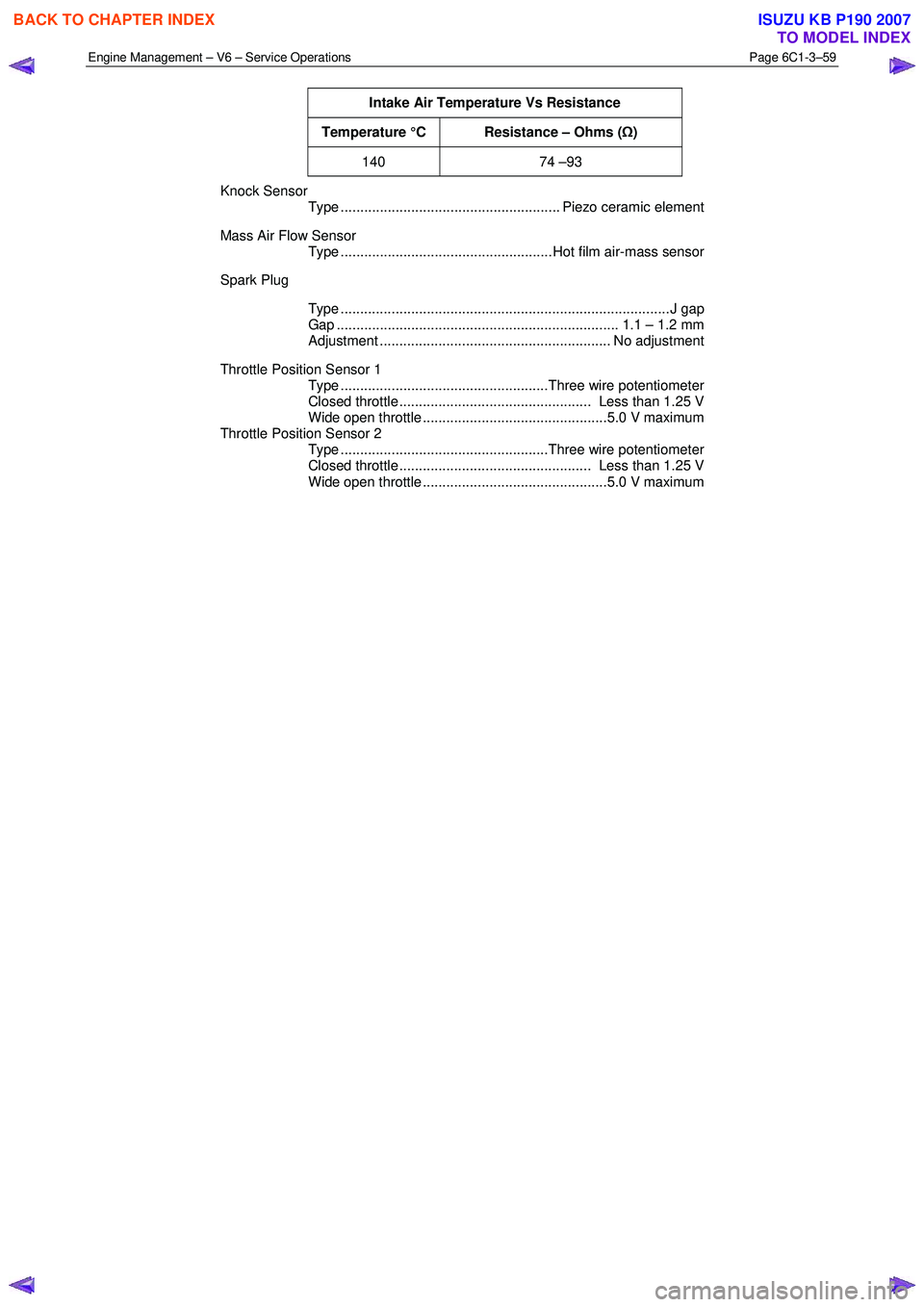
Intake Air Temperature Vs Resistance
Temperature °C Resistance – Ohms (Ω)
140 74 –93
Knock Sensor
Type ........................................................ Piezo ceramic element
Mass Air Flow Sensor
Type ......................................................Hot film air-mass sensor
Spark Plug
Type ....................................................................................J gap
Gap ........................................................................ 1.1 – 1.2 mm
Adjustment ........................................................... No adjustment
Throttle Position Sensor 1
Type .....................................................Three wire potentiometer
Closed throttle ................................................. Less than 1.25 V
Wide open throttle ...............................................5.0 V maximum
Throttle Position Sensor 2
Type .....................................................Three wire potentiometer
Closed throttle ................................................. Less than 1.25 V
Wide open throttle ...............................................5.0 V maximum
BACK TO CHAPTER INDEX
TO MODEL INDEX
ISUZU KB P190 2007
Page 3584 of 6020
Engine Management – V6 – Service Operations Page 6C1-3–60
4 Assembly Lubricants
Camshaft Position (CMP) Sensor O-ring ........................................... Engine Oil
Crankshaft Position (CKP) Sensor .................................................... Engine Oil
Evaporative Emission (EVAP) Canister Purge Valve
Quick Connect Fitting ........................................................................ Engine Oil
Fuel Feed Hose Quick Connect Fitting .............................................. Engine Oil
Fuel Injector Seals............................................................................. Engine Oil
Heated Oxygen Sensor (HO2S) – All .............................. Anti-seize Compound
Ignition Coil Boot .......................................................................Talcum Powder
Ignition Coil Sealing Rubber .............................................................. Engine Oil
BACK TO CHAPTER INDEX
TO MODEL INDEX
ISUZU KB P190 2007
Page 3585 of 6020

Engine Management – V6 – Service Operations Page 6C1-3–61
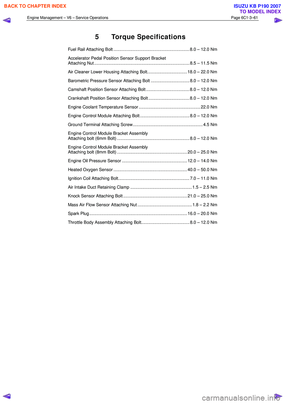
5 Torque Specifications
Fuel Rail Attaching Bolt ............................................................... 8.0 – 12.0 Nm
Accelerator Pedal Position Sensor Support Bracket
Attaching Nut ............................................................................... 8.5 – 11.5 Nm
Air Cleaner Lower Housing Attaching Bolt................................. 18.0 – 22.0 Nm
Barometric Pressure Sensor Attaching Bolt ................................ 8.0 – 12.0 Nm
Camshaft Position Sensor Attaching Bolt .................................... 8.0 – 12.0 Nm
Crankshaft Position Sensor Attaching Bolt .................................. 8.0 – 12.0 Nm
Engine Coolant Temperature Sensor ................................................... 22.0 Nm
Engine Control Module Attaching Bolt ......................................... 8.0 – 12.0 Nm
Ground Terminal Attaching Screw.......................................................... 4.5 Nm
Engine Control Module Bracket Assembly
Attaching bolt (6mm Bolt) ............................................................ 8.0 – 12.0 Nm
Engine Control Module Bracket Assembly
Attaching bolt (8mm Bolt) .......................................................... 20.0 – 25.0 Nm
Engine Oil Pressure Sensor ...................................................... 12.0 – 14.0 Nm
Heated Oxygen Sensor ............................................................. 40.0 – 50.0 Nm
Ignition Coil Attaching Bolt........................................................... 7.0 – 11.0 Nm
Air Intake Duct Retaining Clamp ................................................... 1.5 – 2.5 Nm
Knock Sensor Attaching Bolt ..................................................... 21.0 – 25.0 Nm
Mass Air Flow Sensor Attaching Nut ............................................. 1.8 – 2.2 Nm
Spark Plug ................................................................................. 16.0 – 20.0 Nm
Throttle Body Assembly Attaching Bolt........................................ 8.0 – 12.0 Nm
BACK TO CHAPTER INDEX
TO MODEL INDEX
ISUZU KB P190 2007
Page 3587 of 6020
Engine Management – V6 – Service Operations Page 6C1-3–63
J 41712
Oil Pressure Sensor Socket
Used in conjunction with 3/8” drive
socket equipment to remove / reinstall
oil pressure sensor.
Previously released Desirable
J 23738-A
Vacuum Pump (20 in. Hg Minimum)
Used for many applications where a
controlled vacuum is required to be
applied.
Previously released and also
commercially available Mandatory
N/A
Technical Information System (TIS)
CD ROM
Available to Authorised Dealers. Mandatory
BACK TO CHAPTER INDEX
TO MODEL INDEX
ISUZU KB P190 2007
Page 3628 of 6020
Starting System – V6 Page 6D1-2–20
6 Fit the rear lifting brackets: EN–46114 (1) to the
engine, then hook the chains from the engine hoist
onto the rear lifting bracket.
7 Remove the oil level indicator tube, Refer to 6A1 Engine Mechanical – V6.
Figure 6D1-2 – 9
8 Remove the left hand side knock sensor (1) from the engine block.
Figure 6D1-2 – 10
9 Remove the left hand side engine mount, then using the engine hoist raise the engine to give sufficient
clearance to remove the starter motor.
Figure 6D1-2 – 11
BACK TO CHAPTER INDEX
TO MODEL INDEX
ISUZU KB P190 2007
Page 3629 of 6020

Starting System – V6 Page 6D1-2–21
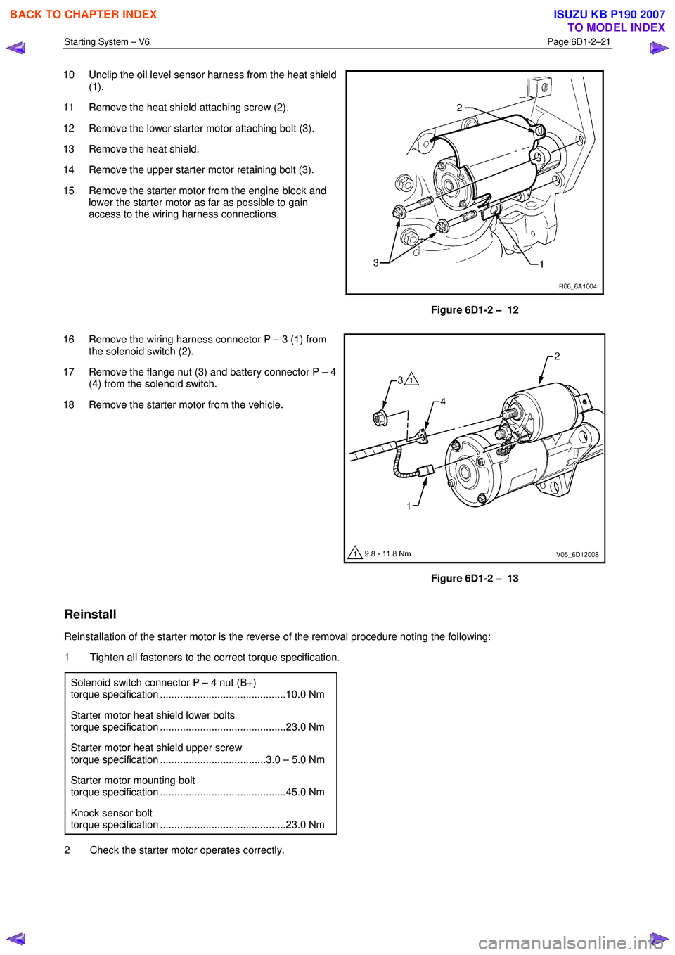
10 Unclip the oil level sensor harness from the heat shield
(1).
11 Remove the heat shield attaching screw (2).
12 Remove the lower starter motor attaching bolt (3).
13 Remove the heat shield.
14 Remove the upper starter motor retaining bolt (3).
15 Remove the starter motor from the engine block and lower the starter motor as far as possible to gain
access to the wiring harness connections.
Figure 6D1-2 – 12
16 Remove the wiring harness connector P – 3 (1) from the solenoid switch (2).
17 Remove the flange nut (3) and battery connector P – 4 (4) from the solenoid switch.
18 Remove the starter motor from the vehicle.
Figure 6D1-2 – 13
Reinstall
Reinstallation of the starter motor is the reverse of the removal procedure noting the following:
1 Tighten all fasteners to the correct torque specification.
Solenoid switch connector P – 4 nut (B+)
torque specification ............................................10.0 Nm
Starter motor heat shield lower bolts
torque specification ............................................23.0 Nm
Starter motor heat shield upper screw
torque specification .....................................3.0 – 5.0 Nm
Starter motor mounting bolt
torque specification ............................................45.0 Nm
Knock sensor bolt
torque specification ............................................23.0 Nm
2 Check the starter motor operates correctly.
BACK TO CHAPTER INDEX
TO MODEL INDEX
ISUZU KB P190 2007
Page 3639 of 6020
Starting System – V6 Page 6D1-2–31
6 Torque Wrench Specifications
..................................................................................................................... Nm
Solenoid Switch Mounting Screw ........................................................ 4.1 – 7.6
Solenoid Switch Terminal M Nut ................................................................ 10.0
Solenoid Switch Terminal P – 3 Nut ........................................................... 10.0
Starter Motor Mounting Bolt........................................................................ 45.0
Knock Sensor Bolt ................................................................................ 23.0 Nm
Starter Motor Heat Shield Lower Bolt ................................................... 23.0 Nm
Starter Motor Heat Shield Upper Screw ........................................ 3.0 – 5.0 Nm
BACK TO CHAPTER INDEX
TO MODEL INDEX
ISUZU KB P190 2007