2007 ISUZU KB P190 Circuit
[x] Cancel search: CircuitPage 3625 of 6020
Starting System – V6 Page 6D1-2–17
Starter Motor Ground Test
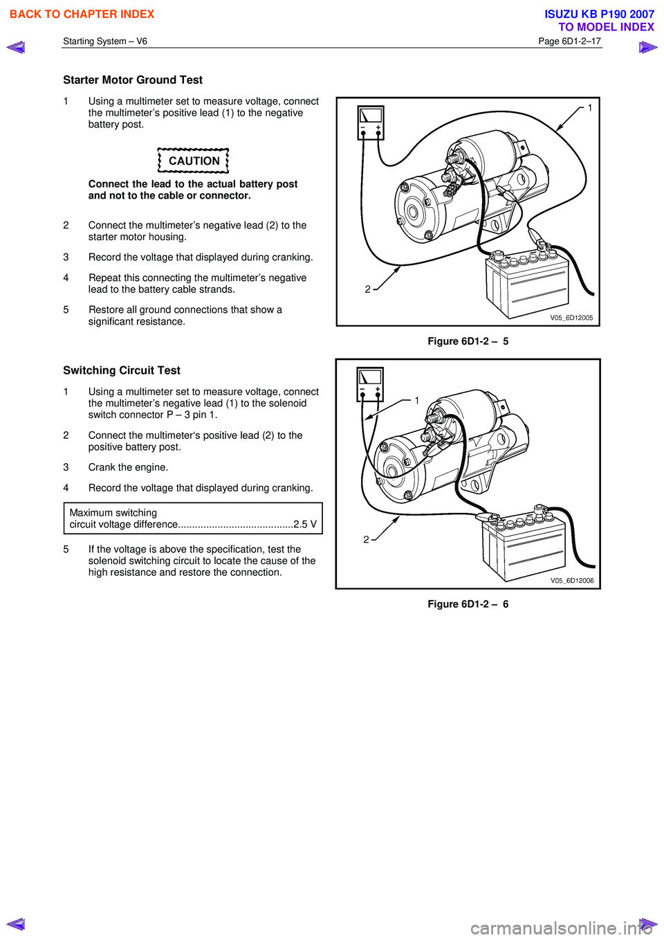
1 Using a multimeter set to measure voltage, connect
the multimeter’s positive lead (1) to the negative
battery post.
Connect the lead to the actual battery post
and not to the cable or connector.
2 Connect the multimeter’s negative lead (2) to the starter motor housing.
3 Record the voltage that displayed during cranking.
4 Repeat this connecting the multimeter’s negative lead to the battery cable strands.
5 Restore all ground connections that show a significant resistance.
Figure 6D1-2 – 5
Switching Circuit Test
1 Using a multimeter set to measure voltage, connect
the multimeter’s negative lead (1) to the solenoid
switch connector P – 3 pin 1.
2 Connect the multimeter‘s positive lead (2) to the positive battery post.
3 Crank the engine.
4 Record the voltage that displayed during cranking.
Maximum switching
circuit voltage difference.........................................2.5 V
5 If the voltage is above the specification, test the solenoid switching circuit to locate the cause of the
high resistance and restore the connection.
Figure 6D1-2 – 6
BACK TO CHAPTER INDEX
TO MODEL INDEX
ISUZU KB P190 2007
Page 3637 of 6020
Starting System – V6 Page 6D1-2–29
27 Replace the solenoid switch if the test lamp
illuminates poorly.
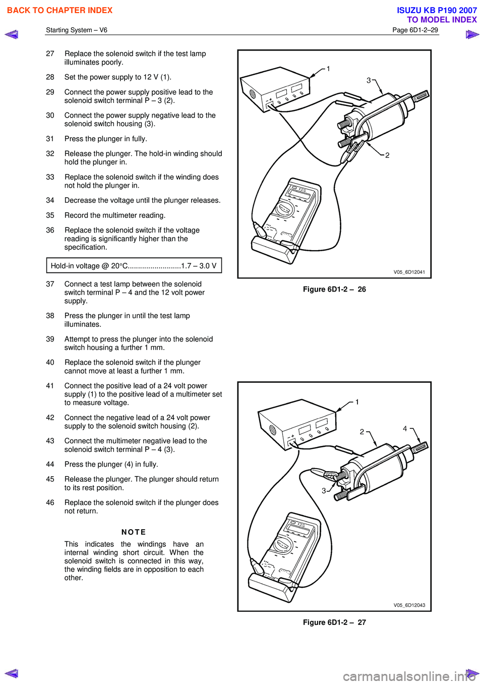
28 Set the power supply to 12 V (1).
29 Connect the power supply positive lead to the solenoid switch terminal P – 3 (2).
30 Connect the power supply negative lead to the solenoid switch housing (3).
31 Press the plunger in fully.
32 Release the plunger. The hold-in winding should hold the plunger in.
33 Replace the solenoid switch if the winding does not hold the plunger in.
34 Decrease the voltage until the plunger releases.
35 Record the multimeter reading.
36 Replace the solenoid switch if the voltage reading is significantly higher than the
specification.
Hold-in voltage @ 20 °C..........................1.7 – 3.0 V
37 Connect a test lamp between the solenoid
switch terminal P – 4 and the 12 volt power
supply.
38 Press the plunger in until the test lamp illuminates.
39 Attempt to press the plunger into the solenoid switch housing a further 1 mm.
40 Replace the solenoid switch if the plunger cannot move at least a further 1 mm.
Figure 6D1-2 – 26
41 Connect the positive lead of a 24 volt power supply (1) to the positive lead of a multimeter set
to measure voltage.
42 Connect the negative lead of a 24 volt power supply to the solenoid switch housing (2).
43 Connect the multimeter negative lead to the solenoid switch terminal P – 4 (3).
44 Press the plunger (4) in fully.
45 Release the plunger. The plunger should return to its rest position.
46 Replace the solenoid switch if the plunger does not return.
NOTE
This indicates the windings have an
internal winding short circuit. When the
solenoid switch is connected in this way,
the winding fields are in opposition to each
other.
Figure 6D1-2 – 27
BACK TO CHAPTER INDEX
TO MODEL INDEX
ISUZU KB P190 2007
Page 3640 of 6020
Starting System – V6 Page 6D1-2–32
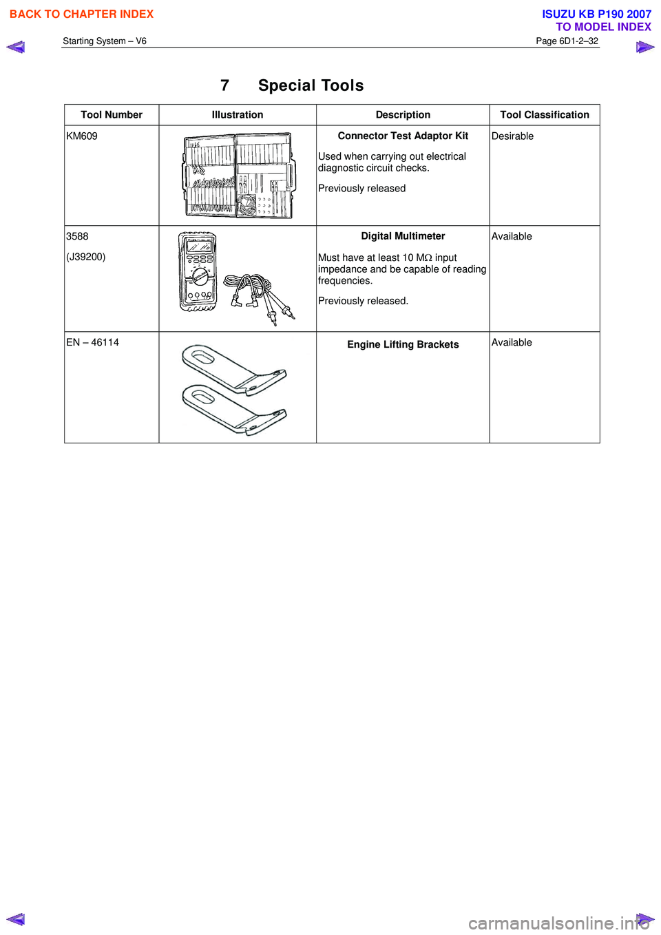
7 Special Tools
Tool Number Illustration Description Tool Classification
KM609
Connector Test Adaptor Kit
Used when carrying out electrical
diagnostic circuit checks.
Previously released
Desirable
3588
(J39200)
Digital Multimeter
Must have at least 10 M Ω input
impedance and be capable of reading
frequencies.
Previously released.
Available
EN – 46114 Engine Lifting Brackets
Available
BACK TO CHAPTER INDEX
TO MODEL INDEX
ISUZU KB P190 2007
Page 3652 of 6020
Battery Page 6D1-3–12
9 Lock the doors and activate the theft deterrent system to arm the vehicle.
10 If the multimeter contains fuses, check they are serviceable.
Test Procedure
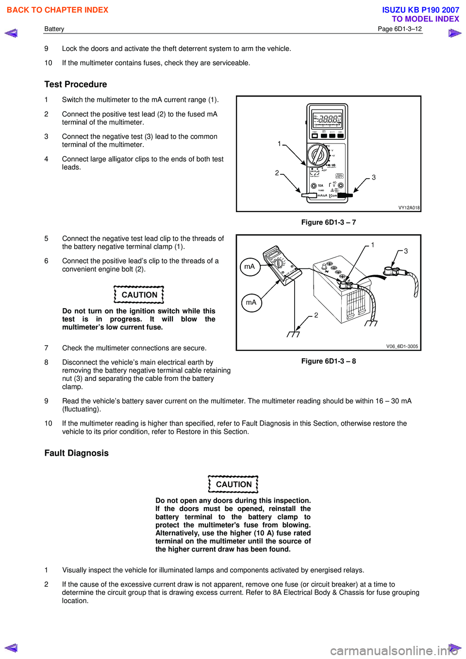
1 Switch the multimeter to the mA current range (1).
2 Connect the positive test lead (2) to the fused mA terminal of the multimeter.
3 Connect the negative test (3) lead to the common terminal of the multimeter.
4 Connect large alligator clips to the ends of both test leads.
Figure 6D1-3 – 7
5 Connect the negative test lead clip to the threads of the battery negative terminal clamp (1).
6 Connect the positive lead’s clip to the threads of a convenient engine bolt (2).
Do not turn on the ignition switch while this
test is in progress. It will blow the
multimeter’s low current fuse.
7 Check the multimeter connections are secure.
8 Disconnect the vehicle’s main electrical earth by removing the battery negative terminal cable retaining
nut (3) and separating the cable from the battery
clamp.
Figure 6D1-3 – 8
9 Read the vehicle’s battery saver current on the multimeter. The multimeter reading should be within 16 – 30 mA (fluctuating).
10 If the multimeter reading is higher than specified, refer to Fault Diagnosis in this Section, otherwise restore the vehicle to its prior condition, refer to Restore in this Section.
Fault Diagnosis
Do not open any doors during this inspection.
If the doors must be opened, reinstall the
battery terminal to the battery clamp to
protect the multimeter's fuse from blowing.
Alternatively, use the higher (10 A) fuse rated
terminal on the multimeter until the source of
the higher current draw has been found.
1 Visually inspect the vehicle for illuminated lamps and components activated by energised relays.
2 If the cause of the excessive current draw is not apparent, remove one fuse (or circuit breaker) at a time to determine the circuit group that is drawing excess current. Refer to 8A Electrical Body & Chassis for fuse grouping
location.
BACK TO CHAPTER INDEX
TO MODEL INDEX
ISUZU KB P190 2007
Page 3653 of 6020
Battery Page 6D1-3–13
3 W hen the circuit group is determined, install the fuse / circuit breaker and identify the specific circuit within this
group that is drawing the excess current. Disconnect the wiring harness connectors in this circuit group one at a
time. Refer to 8A Electrical Body & Chassis.
4 W hen the cause is disconnected, the multimeter reading should drop to the correct reading as outlined in Step 9 of the Test Procedure in this Section.
5 If required, remove the components in this circuit one at a time to determine the cause of the excessive standing current. Refer to 8A Electrical Body & Chassis.
6 Repair the fault, refer to 8A Electrical Body & Chassis.
7 Ensure any fuses, circuit breakers and connectors that have been removed are secure.
Restore
1 Reconnect the electrical earth cable to the battery terminal and tighten the nut to the correct torque specification.
Battery terminal nut
torque specification .....................................2.0 – 5.0 Nm
2 Disconnect the multimeter connections.
BACK TO CHAPTER INDEX
TO MODEL INDEX
ISUZU KB P190 2007
Page 3661 of 6020
Battery Page 6D1-3–21
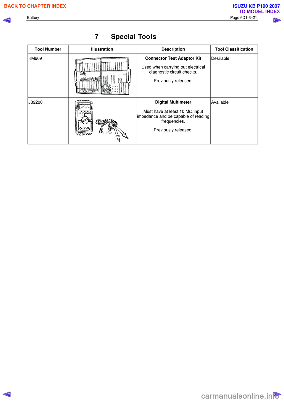
7 Special Tools
Tool Number Illustration Description Tool Classification
KM609 Connector Test Adaptor Kit
Used when carrying out electrical diagnostic circuit checks.
Previously released. Desirable
J39200
Digital Multimeter
Must have at least 10 M Ω input
impedance and be capable of reading frequencies.
Previously released. Available
BACK TO CHAPTER INDEX
TO MODEL INDEX
ISUZU KB P190 2007
Page 3662 of 6020
Powertrain Interface Module – V6 Page 6E1–1
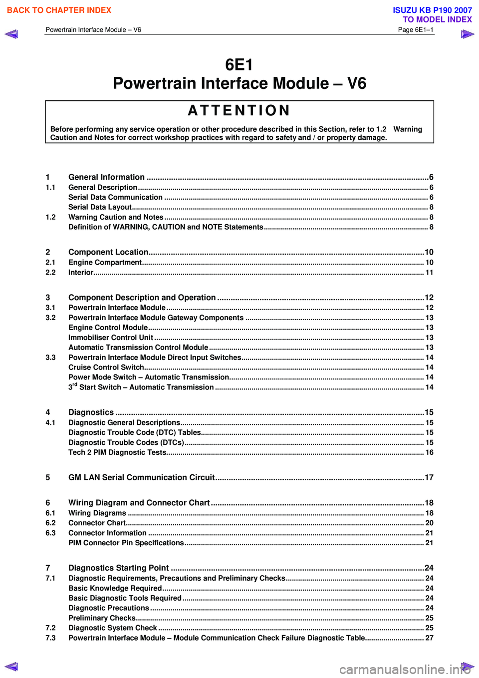
6E1
Powertrain Interface Module – V6
ATTENTION
Before performing any service operation or other procedure described in this Section, refer to 1.2 Warning
Caution and Notes for correct workshop practices with regard to safety and / or property damage.
1 General Information ............................................................................................................ ...................6
1.1 General Description ............................................................................................................ ................................... 6
Serial Data Communication .................................................................................................................................. 6
Serial Data Layout.................................................................................................................................................. 8
1.2 Warning Caution and Notes .................................................................................................................................. 8
Definition of WARNING, CAUTION and NOTE Statements ............................................................................. .... 8
2 Component Location............................................................................................................................10
2.1 Engine Compartment............................................................................................................. .............................. 10
2.2 Interior................................................................................................................................................................... 11
3 Component Description and Operation ............................................................................................ .12
3.1 Powertrain Interface Module ............................................................................................................................... 12
3.2 Powertrain Interface Module Gateway Components ................................................................................. ....... 13
Engine Control Module........................................................................................................................................ 13
Immobiliser Control Unit ..................................................................................................................................... 13
Automatic Transmission Control Module .......................................................................................... ................ 13
3.3 Powertrain Interface Module Direct Input Switches.............................................................................. ............ 14
Cruise Control Switch.......................................................................................................................................... 14
Power Mode Switch – Automatic Transmission..................................................................................... ........... 14
3rd Start Switch – Automatic Transmission ....................................................................................................... 14
4 Diagnostics ...........................................................................................................................................15
4.1 Diagnostic General Descriptions................................................................................................ ........................ 15
Diagnostic Trouble Code (DTC) Tables........................................................................................... ................... 15
Diagnostic Trouble Codes (DTCs) ...................................................................................................................... 15
Tech 2 PIM Diagnostic Tests............................................................................................................................... 16
5 GM LAN Serial Communication Circuit ............................................................................................ ..17
6 Wiring Diagram and Connector Chart ................................................................................................18
6.1 Wiring Diagrams .................................................................................................................................................. 18
6.2 Connector Chart................................................................................................................................................... 20
6.3 Connector Information .......................................................................................................... .............................. 21
PIM Connector Pin Specifications ............................................................................................... ....................... 21
7 Diagnostics Starting Point ..................................................................................................................24
7.1 Diagnostic Requirements, Precautions and Preliminary Checks .................................................................... 24
Basic Knowledge Required ................................................................................................................................. 24
Basic Diagnostic Tools Required ................................................................................................ ....................... 24
Diagnostic Precautions ....................................................................................................................................... 24
Preliminary Checks.............................................................................................................................................. 25
7.2 Diagnostic System Check ........................................................................................................ ........................... 25
7.3 Powertrain Interface Module – Module Communication Check Failure Diagnostic Table............................. 27
BACK TO CHAPTER INDEX
TO MODEL INDEX
ISUZU KB P190 2007
Page 3663 of 6020
Powertrain Interface Module – V6 Page 6E1–2
8 Intermittent Fault Conditions ..............................................................................................................29
8.1 Intermittent Conditions Diagnostic Table ....................................................................................... ................... 29
Description ........................................................................................................................................................... 29
Diagnostic Table .................................................................................................................................................. 29
9 DTC Tables ............................................................................................................................................31
9.1 DTC C0550 – PIM Internal Fault ................................................................................................. ......................... 31
DTC Description ................................................................................................................................................... 31
Circuit Description ............................................................................................................................................... 31
Additional Information......................................................................................................... ................................ 31
Conditions for Running the DTC ................................................................................................. ....................... 31
Conditions for Setting the DTC........................................................................................................................... 31
Action Taken When the DTC Sets ................................................................................................. ..................... 31
Conditions for Clearing the DTC ........................................................................................................................ 31
Test Description ................................................................................................................................................... 31
DTC C0550 Diagnostic Table ..................................................................................................... ......................... 32
9.2 DTC U2100 – No Communication With CAN Bus (High Speed) ....................................................................... 32
DTC Description ................................................................................................................................................... 32
Circuit Description ............................................................................................................................................... 32
Additional Information......................................................................................................... ................................ 32
Conditions for Running the DTC ................................................................................................. ....................... 33
Conditions for Setting the DTC........................................................................................................................... 33
Action Taken When the DTC Sets ................................................................................................. ..................... 33
Conditions for Clearing the DTC ........................................................................................................................ 33
Test Description ................................................................................................................................................... 33
DTC U2100 Diagnostic Table ..................................................................................................... ......................... 33
9.3 DTC U2105 – CAN Bus No Communication With Engine Control Module ...................................................... 35
DTC Description ................................................................................................................................................... 35
Circuit Description ............................................................................................................................................... 35
Additional Information......................................................................................................... ................................ 35
Conditions for Running the DTC ................................................................................................. ....................... 35
Conditions for Setting the DTC........................................................................................................................... 35
Action Taken When the DTC Sets ................................................................................................. ..................... 35
Conditions for Clearing the DTC ........................................................................................................................ 36
Test Description ................................................................................................................................................... 36
DTC U2105 Diagnostic Table ..................................................................................................... ......................... 36
9.4 DTC U2106 – CAN Bus No Communication With Transmission Control Module........................................... 38
DTC Description ................................................................................................................................................... 38
Circuit Description ............................................................................................................................................... 38
Additional Information......................................................................................................... ................................ 38
Conditions for Running the DTC ................................................................................................. ....................... 38
Conditions for Setting the DTC........................................................................................................................... 38
Action Taken When the DTC Sets ................................................................................................. ..................... 38
Conditions for Clearing the DTC ........................................................................................................................ 38
Test Description ................................................................................................................................................... 38
DTC U2106 Diagnostic Table ..................................................................................................... ......................... 39
9.5 DTC B0565 – Coolant Temperature Gauge Circuit High Current ..................................................................... 40
9.6 DTC B0575 – Fuel Gauge Circuit High Current ................................................................................................. 40
9.7 DTC B3598 – Cruise Control Cancel Signal Malfunction........................................................................... ....... 41
DTC Description ................................................................................................................................................... 41
Circuit Description ............................................................................................................................................... 41
Additional Information......................................................................................................... ................................ 41
Conditions for Running the DTC ................................................................................................. ....................... 41
Conditions for Setting the DTC........................................................................................................................... 41
Action Taken When the DTC Sets ................................................................................................. ..................... 41
Conditions for Clearing the DTC ........................................................................................................................ 41
Test Description ................................................................................................................................................... 42
DTC B3628 Diagnostic Table ..................................................................................................... ......................... 42
9.8 DTC B3627 – Cruise Control Resume Signal Malfunction........................................................................... ..... 43
BACK TO CHAPTER INDEX
TO MODEL INDEX
ISUZU KB P190 2007