2007 ISUZU KB P190 Circuit
[x] Cancel search: CircuitPage 3664 of 6020
Powertrain Interface Module – V6 Page 6E1–3
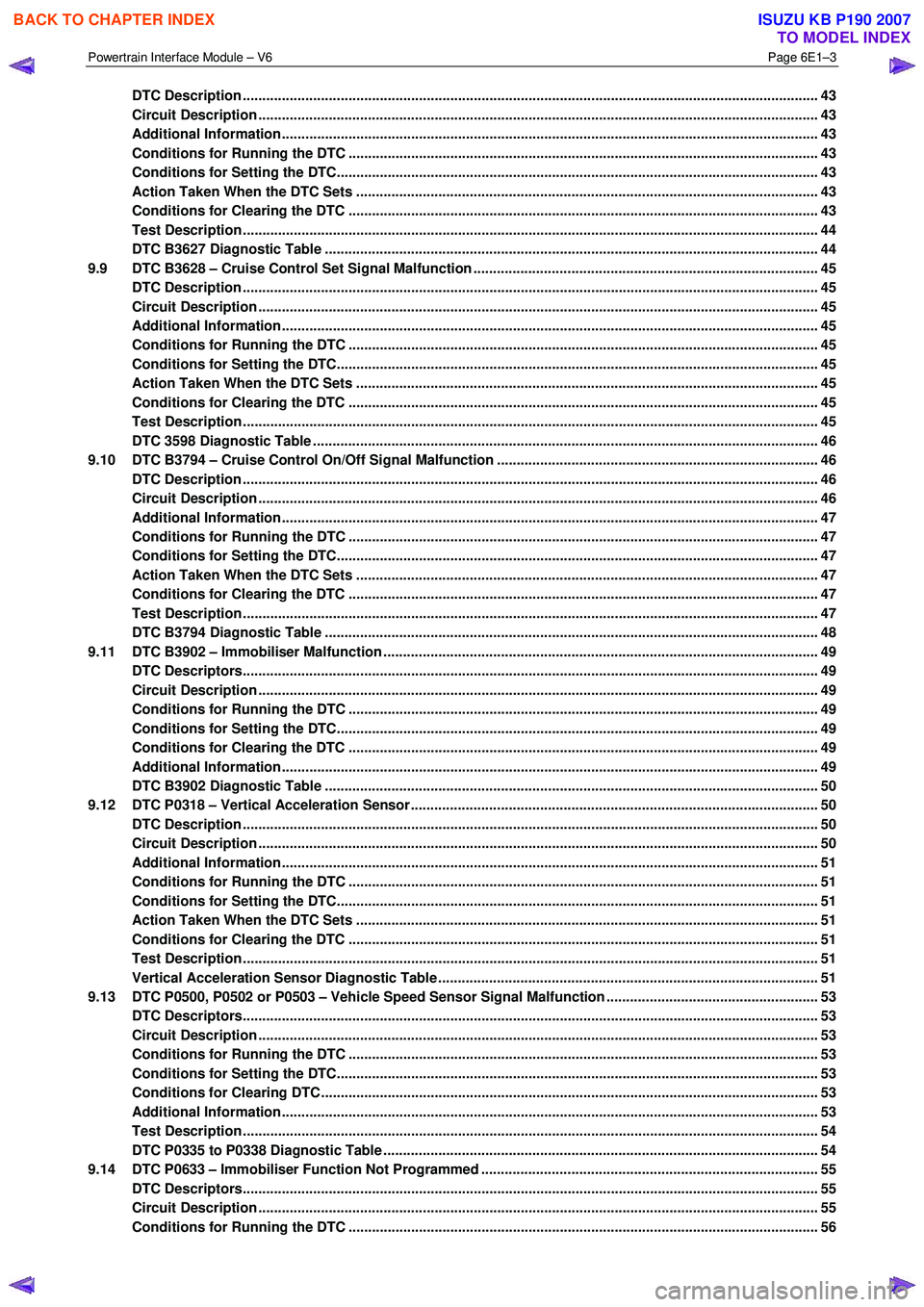
DTC Description ................................................................................................................................................... 43
Circuit Description ............................................................................................................................................... 43
Additional Information......................................................................................................... ................................ 43
Conditions for Running the DTC ................................................................................................. ....................... 43
Conditions for Setting the DTC........................................................................................................................... 43
Action Taken When the DTC Sets ................................................................................................. ..................... 43
Conditions for Clearing the DTC ........................................................................................................................ 43
Test Description ................................................................................................................................................... 44
DTC B3627 Diagnostic Table ..................................................................................................... ......................... 44
9.9 DTC B3628 – Cruise Control Set Signal Malfunction .............................................................................. .......... 45
DTC Description ................................................................................................................................................... 45
Circuit Description ............................................................................................................................................... 45
Additional Information......................................................................................................... ................................ 45
Conditions for Running the DTC ................................................................................................. ....................... 45
Conditions for Setting the DTC........................................................................................................................... 45
Action Taken When the DTC Sets ................................................................................................. ..................... 45
Conditions for Clearing the DTC ........................................................................................................................ 45
Test Description ................................................................................................................................................... 45
DTC 3598 Diagnostic Table ...................................................................................................... ........................... 46
9.10 DTC B3794 – Cruise Control On/Off Signal Malfunction ........................................................................... ....... 46
DTC Description ................................................................................................................................................... 46
Circuit Description ............................................................................................................................................... 46
Additional Information......................................................................................................... ................................ 47
Conditions for Running the DTC ................................................................................................. ....................... 47
Conditions for Setting the DTC........................................................................................................................... 47
Action Taken When the DTC Sets ................................................................................................. ..................... 47
Conditions for Clearing the DTC ........................................................................................................................ 47
Test Description ................................................................................................................................................... 47
DTC B3794 Diagnostic Table ..................................................................................................... ......................... 48
9.11 DTC B3902 – Immobiliser Malfunction ............................................................................................ ................... 49
DTC Descriptors................................................................................................................................................... 49
Circuit Description ............................................................................................................................................... 49
Conditions for Running the DTC ................................................................................................. ....................... 49
Conditions for Setting the DTC........................................................................................................................... 49
Conditions for Clearing the DTC ................................................................................................ ........................ 49
Additional Information......................................................................................................................................... 49
DTC B3902 Diagnostic Table ..................................................................................................... ......................... 50
9.12 DTC P0318 – Vertical Acceleration Sensor....................................................................................... ................. 50
DTC Description ................................................................................................................................................... 50
Circuit Description ............................................................................................................................................... 50
Additional Information......................................................................................................... ................................ 51
Conditions for Running the DTC ................................................................................................. ....................... 51
Conditions for Setting the DTC........................................................................................................................... 51
Action Taken When the DTC Sets ................................................................................................. ..................... 51
Conditions for Clearing the DTC ........................................................................................................................ 51
Test Description ................................................................................................................................................... 51
Vertical Acceleration Sensor Diagnostic Table .................................................................................. ............... 51
9.13 DTC P0500, P0502 or P0503 – Vehicle Speed Sensor Signal Malfunction ...................................................... 53
DTC Descriptors................................................................................................................................................... 53
Circuit Description ............................................................................................................................................... 53
Conditions for Running the DTC ................................................................................................. ....................... 53
Conditions for Setting the DTC........................................................................................................................... 53
Conditions for Clearing DTC ............................................................................................................................... 53
Additional Information......................................................................................................................................... 53
Test Description ................................................................................................................................................... 54
DTC P0335 to P0338 Diagnostic Table ............................................................................................ ................... 54
9.14 DTC P0633 – Immobiliser Function Not Programmed ................................................................................ ...... 55
DTC Descriptors................................................................................................................................................... 55
Circuit Description ............................................................................................................................................... 55
Conditions for Running the DTC ................................................................................................. ....................... 56
BACK TO CHAPTER INDEX
TO MODEL INDEX
ISUZU KB P190 2007
Page 3665 of 6020
Powertrain Interface Module – V6 Page 6E1–4
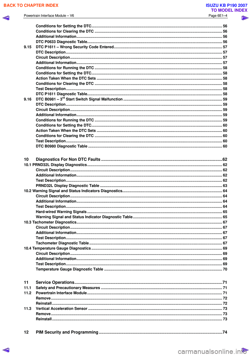
Conditions for Setting the DTC........................................................................................................................... 56
Conditions for Clearing the DTC ................................................................................................ ........................ 56
Additional Information......................................................................................................................................... 56
DTC P0633 Diagnostic Table..................................................................................................... .......................... 56
9.15 DTC P1611 – Wrong Security Code Entered........................................................................................ .............. 57
DTC Description ................................................................................................................................................... 57
Circuit Description ............................................................................................................................................... 57
Additional Information......................................................................................................... ................................ 57
Conditions for Running the DTC ................................................................................................. ....................... 58
Conditions for Setting the DTC........................................................................................................................... 58
Action Taken When the DTC Sets ................................................................................................. ..................... 58
Conditions for Clearing the DTC ........................................................................................................................ 58
Test Description ................................................................................................................................................... 58
DTC P1611 Diagnostic Table..................................................................................................... .......................... 58
9.16 DTC B0981 – 3rd Start Switch Signal Malfunction ............................................................................................. 59
DTC Description ................................................................................................................................................... 59
Circuit Description ............................................................................................................................................... 59
Additional Information......................................................................................................... ................................ 59
Conditions for Running the DTC ................................................................................................. ....................... 59
Conditions for Setting the DTC........................................................................................................................... 60
Action Taken When the DTC Sets ................................................................................................. ..................... 60
Conditions for Clearing the DTC ........................................................................................................................ 60
Test Description ................................................................................................................................................... 60
DTC B0980 Diagnostic Table ..................................................................................................... ......................... 60
10 Diagnostics For Non DTC Faults ................................................................................................. .......62
10.1 PRND32L Display Diagnostics ............................................................................................... ................................ 62
Circuit Description ............................................................................................................................................... 62
Additional Information......................................................................................................... ................................ 62
Test Description ................................................................................................................................................... 62
PRND32L Display Diagnostic Table ............................................................................................... .................... 63
10.2 Warning Signal and Status Indicators Diagnostics.......................................................................... .................... 64
Circuit Description ............................................................................................................................................... 64
Additional Information......................................................................................................... ................................ 64
Test Description ................................................................................................................................................... 64
Hard-wired Warning Signals ..................................................................................................... .......................... 65
Warning Signal and Status Indicator Diagnostic Table ........................................................................... ......... 65
10.3 Tachometer Diagnostics......................................................................................................................................... 67
Circuit Description ............................................................................................................................................... 67
Additional Information......................................................................................................... ................................ 67
Test Description ................................................................................................................................................... 67
Tachometer Diagnostic Table .................................................................................................... ......................... 67
10.4 Temperature Gauge Diagnostics ............................................................................................. .............................. 69
Circuit Description ............................................................................................................................................... 69
Additional Information......................................................................................................... ................................ 69
Test Description ................................................................................................................................................... 69
Temperature Gauge Diagnostic Table ............................................................................................. .................. 70
11 Service Operations ...............................................................................................................................71
11.1 Safety and Precautionary Measures .................................................................................................................. 71
11.2 Powertrain Interface Module ............................................................................................................................... 71
Remove ................................................................................................................................................................. 72
Reinstall ................................................................................................................................................................ 72
11.3 Vertical Acceleration Sensor ................................................................................................... ........................... 73
Remove ................................................................................................................................................................. 73
Reinstall ................................................................................................................................................................ 73
12 PIM Security and Programming ................................................................................................... .......74
BACK TO CHAPTER INDEX
TO MODEL INDEX
ISUZU KB P190 2007
Page 3667 of 6020
Powertrain Interface Module – V6 Page 6E1–6
1 General Information
A powertrain interface module (PIM) is fitted that incorporates the following functionality:
• Communication protocol between the engine control module (ECM) and transmission control module (TCM) is
General Motors Local Area Network (GM LAN).
• Communication protocol between the PIM and immobiliser control unit is keyword 2000.
• ECM to PIM and PIM to immobiliser control unit (ICU) authentication for vehicle security.
• The following switches, where fitted, input directly into the PIM:
• Automatic transmission power mode switch.
• Automatic transmission 3
rd gear start switch.
• Cruise control switch.
1.1 General Description
Serial Data Communication
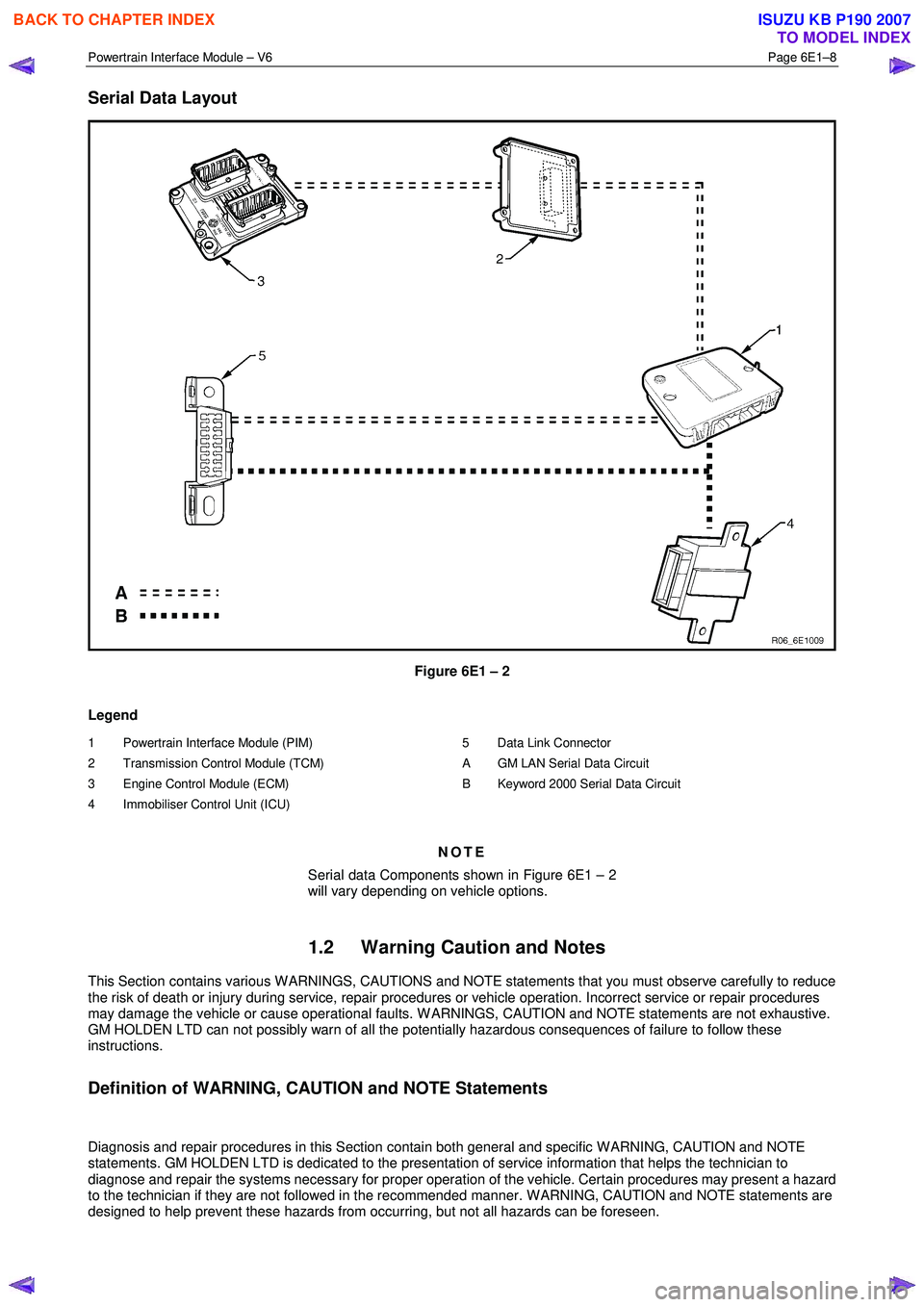
The various electronic control modules communicate with each other through the serial data bus. The ECM and TCM
communicate on the serial data bus using the GM LAN communication protocol. Figure 6E1 – 2 shows the serial data
layout.
NOTE
Serial data components shown in Figure 6E1 – 2
will vary depending on vehicle options.
Bus
A bus is a physical circuit or circuits which provides a communication path between two or more control modules.
GM LAN Serial Data Bus
The GM LAN bus is a two wire circuit (1), refer to Figure 6E1 – 1. The GM LAN bus circuits are terminated with cut-off
resistors (2) which are located inside the two control modules at either end of the bus circuit. The purpose of these cut-off
resistors is to prevent data from returning as an echo after reaching the end of the GM LAN bus circuit.
NOTE
• For illustration purposes, the cut-off resistors
are shown outside of the control modules.
• The two control modules with the cut-off
resistors are the PIM and the ECM.
BACK TO CHAPTER INDEX
TO MODEL INDEX
ISUZU KB P190 2007
Page 3669 of 6020
Powertrain Interface Module – V6 Page 6E1–8
Serial Data Layout
Figure 6E1 – 2
Legend
1 Powertrain Interface Module (PIM)
2 Transmission Control Module (TCM)
3 Engine Control Module (ECM)
4 Immobiliser Control Unit (ICU)
5 Data Link Connector
A GM LAN Serial Data Circuit
B Keyword 2000 Serial Data Circuit
NOTE
Serial data Components shown in Figure 6E1 – 2
will vary depending on vehicle options.
1.2 Warning Caution and Notes
This Section contains various W ARNINGS, CAUTIONS and NOTE statements that you must observe carefully to reduce
the risk of death or injury during service, repair procedures or vehicle operation. Incorrect service or repair procedures
may damage the vehicle or cause operational faults. W ARNINGS, CAUTION and NOTE statements are not exhaustive.
GM HOLDEN LTD can not possibly warn of all the potentially hazardous consequences of failure to follow these
instructions.
Definition of WARNING, CAUTION and NOTE Statements
Diagnosis and repair procedures in this Section contain both general and specific W ARNING, CAUTION and NOTE
statements. GM HOLDEN LTD is dedicated to the presentation of service information that helps the technician to
diagnose and repair the systems necessary for proper operation of the vehicle. Certain procedures may present a hazard
to the technician if they are not followed in the recommended manner. W ARNING, CAUTION and NOTE statements are
designed to help prevent these hazards from occurring, but not all hazards can be foreseen.
BACK TO CHAPTER INDEX
TO MODEL INDEX
ISUZU KB P190 2007
Page 3676 of 6020
Powertrain Interface Module – V6 Page 6E1–15
4 Diagnostics
4.1 Diagnostic General Descriptions
The powertrain interface module (PIM) diagnostic procedure is organised in a logical structure that begins with the
Diagnostic System Check. The Diagnostic System Check directs the diagnostic procedure to the logical steps or
appropriate diagnostic table required to diagnose a PIM fault condition.
The diagnostic tables locate a faulty circuit or component through a logical based process of elimination. Correct use of
the diagnostic tables is essential to reduce diagnostic time and to prevent misdiagnosis.
In addition, the Diagnostic System Check provides the following information:
• identification of the PIM,
• condition of the diagnostic circuit, and
• identification and status of the DTCs if present.
Diagnostic Trouble Code (DTC) Tables
The diagnostic procedure is directed to a diagnostic trouble code (DTC) table if there are DTCs currently stored in the
PIM.
The diagnostic tables are designed to locate a faulty circuit or component through a logical based process of elimination.
The diagnostic tables are developed with the following assumptions:
• the vehicle functioned correctly at the time of assembly,
• there are no multiple faults, and
• the problem currently exists.
Multiple DTCs
W hen performing a DTC check and there are multiple DTCs, the diagnostic process must begin with the most likely DTC
that may trigger other DTCs.
Knowledge of the PIM and Tech 2 limitations are important to reduce diagnostic time and to prevent misdiagnosis. Refer
to 7.1 Diagnostic Requirements, Precautions and Preliminary Checks.
Diagnostic Trouble Codes (DTCs)
W hen the ignition switch is turned on, the PIM performs an internal integrity check that detects and isolates any internal
faults. The PIM also monitors the direct input switches such as the cruise control and the serial data bus for messages
from the control modules on the GM LAN bus. If a fault is detected by the PIM, it will log a Diagnostic Trouble Code
(DTC) that represents the fault detected. The DTCs stored in the PIM may be accessed using Tech 2.
Status of DTCs
The PIM designates the DTCs logged into a Current or History DTC.
Current DTCs
If the fault condition that triggers the DTC is present during the last PIM self test, that DTC will be designated as a current
DTC.
History DTCs
If the fault condition that triggers the DTC is not present during the last PIM self test, that DTC will be designated as a
history DTC.
Conditions for Clearing DTCs
• If there is no DTC logged in the current PIM self test, the current DTC will be cleared.
• If there is no DTC logged after 100 consecutive drive cycles, the history DTC will be cleared.
BACK TO CHAPTER INDEX
TO MODEL INDEX
ISUZU KB P190 2007
Page 3677 of 6020
Powertrain Interface Module – V6 Page 6E1–16
Tech 2 PIM Diagnostic Tests
Tech 2 Limitations
Some DTCs trigger other DTCs to set, which causes Tech 2 to display multiple DTCs. In those situations, Tech 2 may
display more DTCs than is needed to rectify a fault.
W hen Tech 2 displays an output function, it displays only the command given by the PIM. If a connector is disconnected,
that fault will not register in the PIM output function. Tech 2 does not verify the command action.
The service technician must understand the system being diagnosed as well as the correct use and limitations of Tech 2
to be able to perform diagnostic procedures efficiently and successfully.
Tech 2 Intermittent Fault Tests
The following are lists of Tech 2 diagnostic tests that may be used to diagnose intermittent faults:
• W iggle test the suspected PIM wiring harness and connector while observing Tech 2 operating parameters of the
circuit being tested. If Tech 2 read-out fluctuates during this procedure, check the wiring harness circuit for loose
connection.
• Road test the vehicle in conditions that trigger the intermittent fault while an assistant observes the suspected Tech
2 operating parameter data.
• Capture and store data in the Snapshot mode when the fault occurs. The stored data may be replayed at a slower
rate to aid in diagnostics. Refer to Tech 2 User Instructions for more information on the Snapshot function.
• Operate suspected components to test their operation using Tech 2 Output Control Data.
BACK TO CHAPTER INDEX
TO MODEL INDEX
ISUZU KB P190 2007
Page 3678 of 6020
Powertrain Interface Module – V6 Page 6E1–17
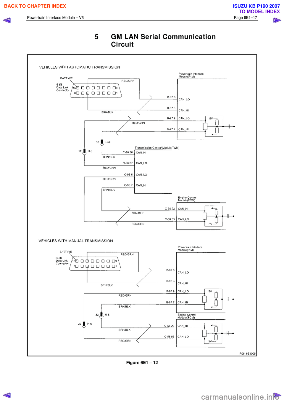
5 GM LAN Serial Communication
Circuit
Figure 6E1 – 12
BACK TO CHAPTER INDEX
TO MODEL INDEX
ISUZU KB P190 2007
Page 3682 of 6020
Powertrain Interface Module – V6 Page 6E1–21
6.3 Connector Information
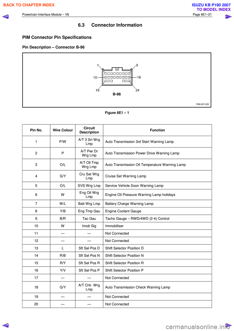
PIM Connector Pin Specifications
Pin Description – Connector B-96
Figure 6E1 – 1
Pin No. Wire Colour Circuit
Description Function
1 P/W
A/T 3 Srt W rg
Lmp Auto Transmission 3rd Start W arning Lamp
2 P
A/T Pwr Dr
W rg Lmp Auto Transmission Power Drive W arning Lamp
3 O/L A/T Oil Tmp
W rg Lmp Auto Transmission Oil Temperature W arning Lamp
4 G/Y
Cru Set W rg
Lmp Cruise Set W arning Lamp
5
O/L SVS W rg Lmp Service Vehicle Soon W arning Lamp
6 W Eng Oil W rg
Lmp Engine Oil Pressure W arning Lamp holidays
7
W /L Batt W rg Lmp Battery Charge W arning Lamp
8 Y/B Eng Tmp Gau Engine Coolant Gauge
9 B/R Tac Gau Tacho Gauge – RW D/4W D (2-4) Control
10 W Imob Sig Immobiliser
11 — — Not Connected
12 — — Not Connected
13 L Sft Sel Pos D Shift Selector Position D
14 R/B Sft Sel Pos N Shift Selector Position N
15 R/Y Sft Sel Pos R Shift Selector Position R
16 Y/V Sft Sel Pos P Shift Selector Position P
17 — — Not Connected
18 G/Y A/T Chk W rg
Lmp Auto Transmission Check W arning Lamp
19 — — Not
Connected
20 — — Not Connected
BACK TO CHAPTER INDEX
TO MODEL INDEX
ISUZU KB P190 2007