2007 ISUZU KB P190 Circuit
[x] Cancel search: CircuitPage 3710 of 6020
Powertrain Interface Module – V6 Page 6E1–49
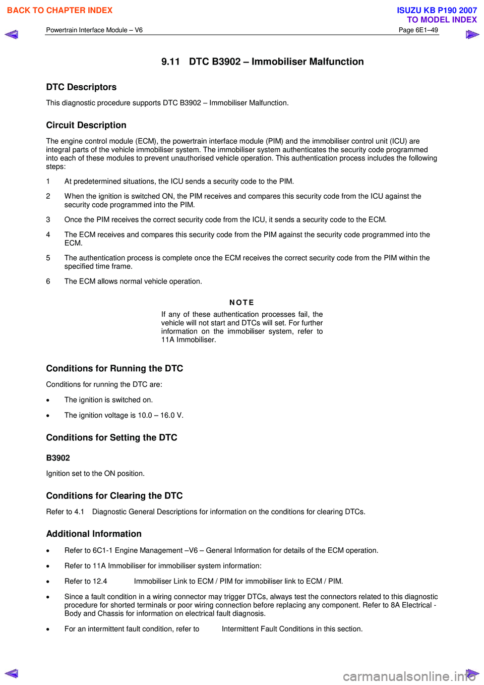
9.11 DTC B3902 – Immobiliser Malfunction
DTC Descriptors
This diagnostic procedure supports DTC B3902 – Immobiliser Malfunction.
Circuit Description
The engine control module (ECM), the powertrain interface module (PIM) and the immobiliser control unit (ICU) are
integral parts of the vehicle immobiliser system. The immobiliser system authenticates the security code programmed
into each of these modules to prevent unauthorised vehicle operation. This authentication process includes the following
steps:
1 At predetermined situations, the ICU sends a security code to the PIM.
2 W hen the ignition is switched ON, the PIM receives and compares this security code from the ICU against the security code programmed into the PIM.
3 Once the PIM receives the correct security code from the ICU, it sends a security code to the ECM.
4 The ECM receives and compares this security code from the PIM against the security code programmed into the ECM.
5 The authentication process is complete once the ECM receives the correct security code from the PIM within the specified time frame.
6 The ECM allows normal vehicle operation.
NOTE
If any of these authentication processes fail, the
vehicle will not start and DTCs will set. For further
information on the immobiliser system, refer to
11A Immobiliser.
Conditions for Running the DTC
Conditions for running the DTC are:
• The ignition is switched on.
• The ignition voltage is 10.0 – 16.0 V.
Conditions for Setting the DTC
B3902
Ignition set to the ON position.
Conditions for Clearing the DTC
Refer to 4.1 Diagnostic General Descriptions for information on the conditions for clearing DTCs.
Additional Information
• Refer to 6C1-1 Engine Management –V6 – General Information for details of the ECM operation.
• Refer to 11A Immobiliser for immobiliser system information:
• Refer to 12.4 Immobiliser Link to ECM / PIM for immobiliser link to ECM / PIM.
• Since a fault condition in a wiring connector may trigger DTCs, always test the connectors related to this diagnostic
procedure for shorted terminals or poor wiring connection before replacing any component. Refer to 8A Electrical -
Body and Chassis for information on electrical fault diagnosis.
• For an intermittent fault condition, refer to Intermittent Fault Conditions in this section.
BACK TO CHAPTER INDEX
TO MODEL INDEX
ISUZU KB P190 2007
Page 3711 of 6020
Powertrain Interface Module – V6 Page 6E1–50
• To assist diagnosis, refer to 6 W iring Diagram and Connector Chart for the system wiring diagram and
connector charts in this section.
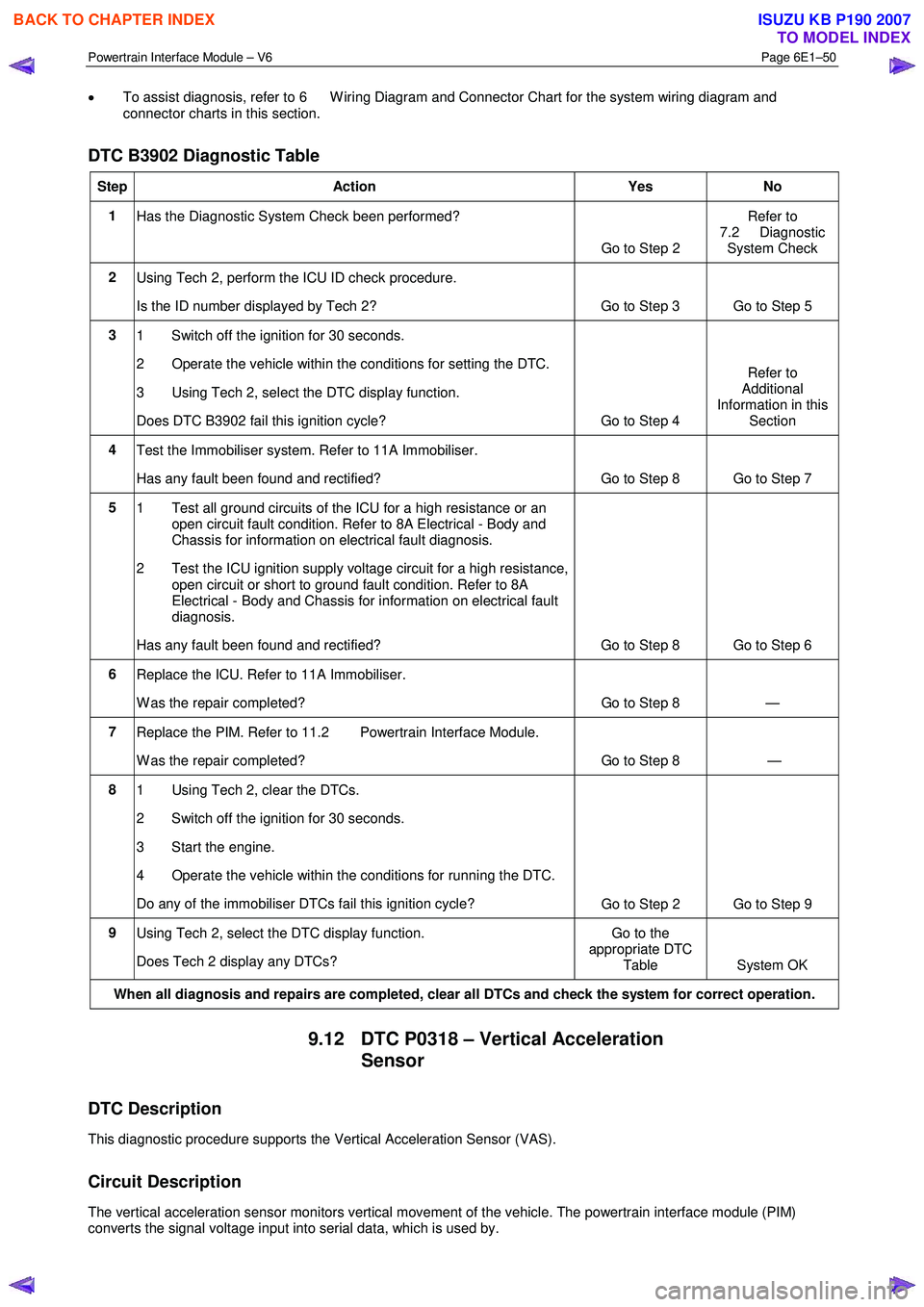
DTC B3902 Diagnostic Table
Step Action Yes No
1
Has the Diagnostic System Check been performed?
Go to Step 2 Refer to
7.2 Diagnostic System Check
2 Using Tech 2, perform the ICU ID check procedure.
Is the ID number displayed by Tech 2? Go to Step 3
Go to Step 5
3 1 Switch off the ignition for 30 seconds.
2 Operate the vehicle within the conditions for setting the DTC.
3 Using Tech 2, select the DTC display function.
Does DTC B3902 fail this ignition cycle? Go to Step 4 Refer to
Additional
Information in this Section
4 Test the Immobiliser system. Refer to 11A Immobiliser.
Has any fault been found and rectified? Go to Step 8 Go to Step 7
5 1 Test all ground circuits of the ICU for a high resistance or an
open circuit fault condition. Refer to 8A Electrical - Body and
Chassis for information on electrical fault diagnosis.
2 Test the ICU ignition supply voltage circuit for a high resistance, open circuit or short to ground fault condition. Refer to 8A
Electrical - Body and Chassis for information on electrical fault
diagnosis.
Has any fault been found and rectified? Go to Step 8 Go to Step 6
6 Replace the ICU. Refer to 11A Immobiliser.
W as the repair completed? Go to Step 8 —
7 Replace the PIM. Refer to 11.2 Powertrain Interface Module.
W as the repair completed? Go to Step 8 —
8 1 Using Tech 2, clear the DTCs.
2 Switch off the ignition for 30 seconds.
3 Start the engine.
4 Operate the vehicle within the conditions for running the DTC.
Do any of the immobiliser DTCs fail this ignition cycle? Go to Step 2 Go to Step 9
9
Using Tech 2, select the DTC display function.
Does Tech 2 display any DTCs? Go to the
appropriate DTC Table System OK
When all diagnosis and repairs are completed, clear all DTCs and check the system for correct operation.
9.12 DTC P0318 – Vertical Acceleration
Sensor
DTC Description
This diagnostic procedure supports the Vertical Acceleration Sensor (VAS).
Circuit Description
The vertical acceleration sensor monitors vertical movement of the vehicle. The powertrain interface module (PIM)
converts the signal voltage input into serial data, which is used by.
BACK TO CHAPTER INDEX
TO MODEL INDEX
ISUZU KB P190 2007
Page 3712 of 6020
Powertrain Interface Module – V6 Page 6E1–51
Additional Information
• Refer to 6 W iring Diagram and Connector Chart for the following information:
• PIM connector illustration and terminal assignment, and
• PIM wiring diagram.
• For intermittent fault conditions, refer to Intermittent Fault Conditions.
• Since fault conditions in a wiring connector may trigger DTCs, always test the connectors related to this diagnostic
procedure for shorted terminals or poor wiring connection before replacing any component. Refer to
8A Electrical - Body and Chassis for information on electrical fault diagnosis.
Conditions for Running the DTC
Conditions for running the DTC are:
• The ignition is switched on.
• The ignition voltage is 10.0 – 16.0 V.
Conditions for Setting the DTC
The DTC will set when the PIM detects a low voltage of <0.41 volts for one second.
The DTC will set when the PIM detects a high voltage of >4.59 volts for one second.
Action Taken When the DTC Sets
W hen the DTC sets, there is no warning lamp displayed on the instrument cluster.
Conditions for Clearing the DTC
The DTC is cleared at the next ignition cycle.
Refer to 4.1 Diagnostic General Descriptions for information on the conditions for clearing DTCs.
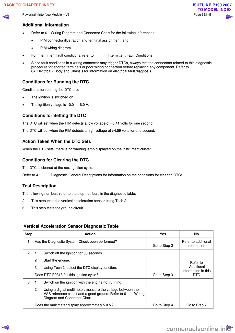
Test Description
The following numbers refer to the step numbers in the diagnostic table:
2 This step tests the vertical acceleration sensor using Tech 2.
6 This step tests the ground circuit.
Vertical Acceleration Sensor Diagnostic Table
Step Action Yes No
1
Has the Diagnostic System Check been performed?
Go to Step 2 Refer to additional
information
2 1 Switch off the ignition for 30 seconds.
2 Start the engine.
3 Using Tech 2, select the DTC display function.
Does DTC P0318 fail this ignition cycle? Go to Step 3 Refer to
Additional
Information in this DTC
3 1 Switch on the ignition with the engine not running.
2 Using a digital multimeter, measure the voltage between the VAS reference circuit and a good ground. Refer to 6 W iring
Diagram and Connector Chart.
Does the multimeter display approximately 5.0 V? Go to Step 4 Go to Step 7
BACK TO CHAPTER INDEX
TO MODEL INDEX
ISUZU KB P190 2007
Page 3713 of 6020
Powertrain Interface Module – V6 Page 6E1–52
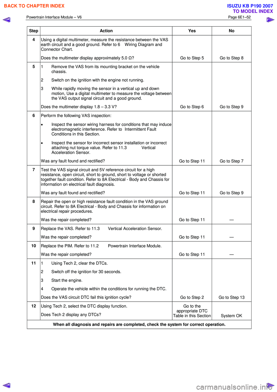
Step Action Yes No
4
Using a digital multimeter, measure the resistance between the VAS
earth circuit and a good ground. Refer to 6 W iring Diagram and
Connector Chart.
Does the multimeter display approximately 5.0 Ω?
Go to Step 5 Go to Step 8
5
1 Remove the VAS from its mounting bracket on the vehicle
chassis.
2 Switch on the ignition with the engine not running.
3 W hile rapidly moving the sensor in a vertical up and down motion, Use a digital multimeter to measure the voltage between
the VAS output signal circuit and a good ground.
Does the multimeter display 1.8 – 3.3 V? Go to Step 6 Go to Step 9
6 Perform the following VAS inspection:
• Inspect the sensor wiring harness for conditions that may induce
electromagnetic interference. Refer to Intermittent Fault
Conditions in this Section.
• Inspect the sensor for incorrect sensor installation or incorrect
attaching nut torque value. Refer to 11.3 Vertical
Acceleration Sensor.
W as any fault found and rectified? Go to Step 11 Go to Step 7
7
Test the VAS signal circuit and 5V reference circuit for a high
resistance, open circuit, short to ground, short to voltage or shorted
together fault condition. Refer to 8A Electrical - Body and Chassis for
information on electrical fault diagnosis.
W as any fault found and rectified? Go to Step 11 Go to Step 9
8
Repair the open or high resistance fault condition in the VAS ground
circuit. Refer to 8A Electrical - Body and Chassis for information on
electrical repair procedures.
W as the repair completed? Go to Step 11 —
9 Replace the VAS. Refer to 11.3 Vertical Acceleration Sensor.
W as the repair completed? Go to Step 11 —
10 Replace the PIM. Refer to 11.2 Powertrain Interface Module.
W as the repair completed? Go to Step 11 —
11 1 Using Tech 2, clear the DTCs.
2 Switch off the ignition for 30 seconds.
3 Start the engine.
4 Operate the vehicle within the conditions for running the DTC.
Does the VAS circuit DTC fail this ignition cycle? Go to Step 2 Go to Step 13
12
Using Tech 2, select the DTC display function.
Does Tech 2 display any DTCs? Go to the
appropriate DTC
Table in this Section System OK
When all diagnosis and repairs are completed, check the system for correct operation.
BACK TO CHAPTER INDEX
TO MODEL INDEX
ISUZU KB P190 2007
Page 3714 of 6020
Powertrain Interface Module – V6 Page 6E1–53
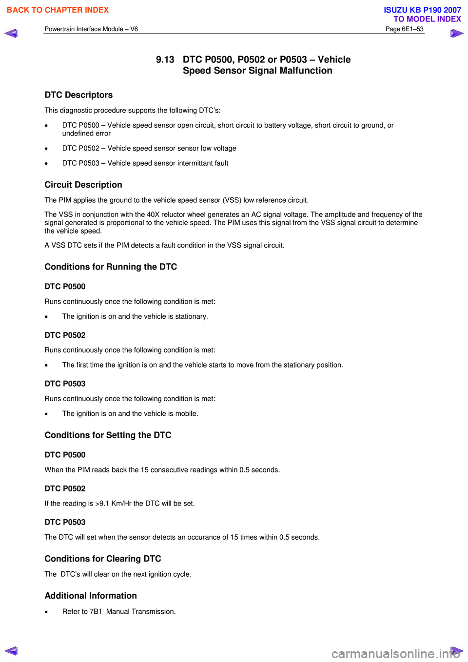
9.13 DTC P0500, P0502 or P0503 – Vehicle
Speed Sensor Signal Malfunction
DTC Descriptors
This diagnostic procedure supports the following DTC’s:
• DTC P0500 – Vehicle speed sensor open circuit, short circuit to battery voltage, short circuit to ground, or
undefined error
• DTC P0502 – Vehicle speed sensor sensor low voltage
• DTC P0503 – Vehicle speed sensor intermittant fault
Circuit Description
The PIM applies the ground to the vehicle speed sensor (VSS) low reference circuit.
The VSS in conjunction with the 40X reluctor wheel generates an AC signal voltage. The amplitude and frequency of the
signal generated is proportional to the vehicle speed. The PIM uses this signal from the VSS signal circuit to determine
the vehicle speed.
A VSS DTC sets if the PIM detects a fault condition in the VSS signal circuit.
Conditions for Running the DTC
DTC P0500
Runs continuously once the following condition is met:
• The ignition is on and the vehicle is stationary.
DTC P0502
Runs continuously once the following condition is met:
• The first time the ignition is on and the vehicle starts to move from the stationary position.
DTC P0503
Runs continuously once the following condition is met:
• The ignition is on and the vehicle is mobile.
Conditions for Setting the DTC
DTC P0500
W hen the PIM reads back the 15 consecutive readings within 0.5 seconds.
DTC P0502
If the reading is >9.1 Km/Hr the DTC will be set.
DTC P0503
The DTC will set when the sensor detects an occurance of 15 times within 0.5 seconds.
Conditions for Clearing DTC
The DTC’s will clear on the next ignition cycle.
Additional Information
• Refer to 7B1_Manual Transmission.
BACK TO CHAPTER INDEX
TO MODEL INDEX
ISUZU KB P190 2007
Page 3715 of 6020
Powertrain Interface Module – V6 Page 6E1–54
• For an intermittent fault condition, refer to Intermittent Fault Conditions in this Section.
• The VSS in conjunction with the 40X reluctor wheel generates an AC signal voltage. The amplitude and frequency
of the signal generated is proportional to the vehicle speed. The PIM uses this signal from the VSS signal circuit to
determine the vehicle speed.
• Since fault condition in a wiring connector may trigger DTCs, always test the connectors related to this diagnostic
procedure for shorted terminals or poor wiring connection before replacing any component. Refer to 8A Electrical -
Body and Chassis for information on electrical fault diagnosis.
• To assist diagnosis, refer to 6 W iring Diagram and Connector Chart in this Section, for the system wiring diagram
and connector charts.
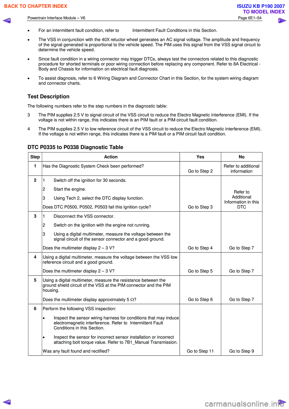
Test Description
The following numbers refer to the step numbers in the diagnostic table:
3 The PIM supplies 2.5 V to signal circuit of the VSS circuit to reduce the Electro Magnetic interference (EMI). If the voltage is not within range, this indicates there is an PIM fault or a PIM circuit fault condition.
4 The PIM supplies 2.5 V to low reference circuit of the VSS circuit to reduce the Electro Magnetic interference (EMI). If the voltage is not within range, this indicates there is a PIM fault or a PIM circuit fault condition.
DTC P0335 to P0338 Diagnostic Table
Step Action Yes No
1
Has the Diagnostic System Check been performed?
Go to Step 2 Refer to additional
information
2 1 Switch off the ignition for 30 seconds.
2 Start the engine.
3 Using Tech 2, select the DTC display function.
Does DTC P0500, P0502, P0503 fail this ignition cycle? Go to Step 3 Refer to
Additional
Information in this DTC
3 1 Disconnect the VSS connector.
2 Switch on the ignition with the engine not running.
3 Using a digital multimeter, measure the voltage between the signal circuit of the sensor connector and a good ground.
Does the multimeter display 2 – 3 V? Go to Step 4 Go to Step 7
4 Using a digital multimeter, measure the voltage between the VSS low
reference circuit and a good ground.
Does the multimeter display 2 – 3 V? Go to Step 5 Go to Step 7
5 Using a digital multimeter, measure the resistance between the
ground shield circuit of the VSS at the PIM connector and the PIM
housing.
Does the multimeter display approximately 5 Ω? Go to Step 6 Go to Step 7
6
Perform the following VSS inspection:
• Inspect the sensor wiring harness for conditions that may induce
electromagnetic interference. Refer to Intermittent Fault
Conditions in this Section.
• Inspect the sensor for incorrect sensor installation or incorrect
attaching bolt torque value. Refer to 7B1_Manual Transmission.
W as any fault found and rectified? Go to Step 11 Go to Step 9
BACK TO CHAPTER INDEX
TO MODEL INDEX
ISUZU KB P190 2007
Page 3716 of 6020
Powertrain Interface Module – V6 Page 6E1–55
Step Action Yes No
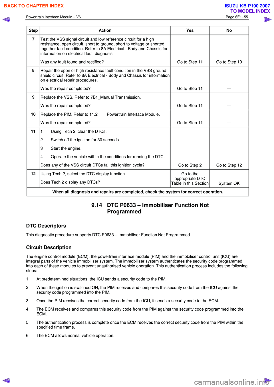
7
Test the VSS signal circuit and low reference circuit for a high
resistance, open circuit, short to ground, short to voltage or shorted
together fault condition. Refer to 8A Electrical - Body and Chassis for
information on electrical fault diagnosis.
W as any fault found and rectified? Go to Step 11 Go to Step 10
8
Repair the open or high resistance fault condition in the VSS ground
shield circuit. Refer to 8A Electrical - Body and Chassis for information
on electrical repair procedures.
W as the repair completed? Go to Step 11 —
9 Replace the VSS. Refer to 7B1_Manual Transmission.
W as the repair completed? Go to Step 11 —
10 Replace the PIM. Refer to 11.2 Powertrain Interface Module.
W as the repair completed? Go to Step 11 —
11 1 Using Tech 2, clear the DTCs.
2 Switch off the ignition for 30 seconds.
3 Start the engine.
4 Operate the vehicle within the conditions for running the DTC.
Does any of the VSS circuit DTCs fail this ignition cycle? Go to Step 2 Go to Step 12
12
Using Tech 2, select the DTC display function.
Does Tech 2 display any DTCs? Go to the
appropriate DTC
Table in this Section System OK
When all diagnosis and repairs are completed, check the system for correct operation.
9.14 DTC P0633 – Immobiliser Function Not
Programmed
DTC Descriptors
This diagnostic procedure supports DTC P0633 – Immobiliser Function Not Programmed.
Circuit Description
The engine control module (ECM), the powertrain interface module (PIM) and the immobiliser control unit (ICU) are
integral parts of the vehicle immobiliser system. The immobiliser system authenticates the security code programmed
into each of these modules to prevent unauthorised vehicle operation. This authentication process includes the following
steps:
1 At predetermined situations, the ICU sends a security code to the PIM.
2 W hen the ignition is switched ON, the PIM receives and compares this security code from the ICU against the security code programmed into the PIM.
3 Once the PIM receives the correct security code from the ICU, it sends a security code to the ECM.
4 The ECM receives and compares this security code from the PIM against the security code programmed into the ECM.
5 The authentication process is complete once the ECM receives the correct security code from the PIM within the specified time frame.
6 The ECM allows normal vehicle operation.
BACK TO CHAPTER INDEX
TO MODEL INDEX
ISUZU KB P190 2007
Page 3718 of 6020
Powertrain Interface Module – V6 Page 6E1–57
Step Action Yes No
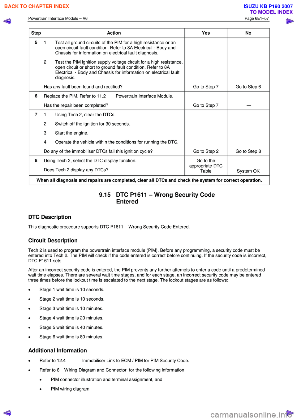
5
1 Test all ground circuits of the PIM for a high resistance or an
open circuit fault condition. Refer to 8A Electrical - Body and
Chassis for information on electrical fault diagnosis.
2 Test the PIM ignition supply voltage circuit for a high resistance, open circuit or short to ground fault condition. Refer to 8A
Electrical - Body and Chassis for information on electrical fault
diagnosis.
Has any fault been found and rectified? Go to Step 7 Go to Step 6
6 Replace the PIM. Refer to 11.2 Powertrain Interface Module.
Has the repair been completed? Go to Step 7 —
7 1 Using Tech 2, clear the DTCs.
2 Switch off the ignition for 30 seconds.
3 Start the engine.
4 Operate the vehicle within the conditions for running the DTC.
Do any of the immobiliser DTCs fail this ignition cycle? Go to Step 2 Go to Step 8
8
Using Tech 2, select the DTC display function.
Does Tech 2 display any DTCs? Go to the
appropriate DTC Table System OK
When all diagnosis and repairs are completed, clear all DTCs and check the system for correct operation.
9.15 DTC P1611 – Wrong Security Code
Entered
DTC Description
This diagnostic procedure supports DTC P1611 – W rong Security Code Entered.
Circuit Description
Tech 2 is used to program the powertrain interface module (PIM). Before any programming, a security code must be
entered into Tech 2. The PIM will check if the code entered is correct before continuing. If the security code is incorrect,
DTC P1611 sets.
After an incorrect security code is entered, the PIM prevents any further attempts to enter a code until a predetermined
wait time elapses. There are several wait time stages, and for each stage, an incorrect security code may be entered
three times before the lockout time is escalated to the next stage. The lockout stages are as follows:
• Stage 1 wait time is 10 seconds.
• Stage 2 wait time is 10 seconds.
• Stage 3 wait time is 10 minutes.
• Stage 4 wait time is 20 minutes.
• Stage 5 wait time is 40 minutes.
• Stage 6 wait time is 80 minutes.
Additional Information
• Refer to 12.4 Immobiliser Link to ECM / PIM for PIM Security Code.
• Refer to 6 W iring Diagram and Connector for the following information:
• PIM connector illustration and terminal assignment, and
• PIM wiring diagram.
BACK TO CHAPTER INDEX
TO MODEL INDEX
ISUZU KB P190 2007