2007 ISUZU KB P190 ECO mode
[x] Cancel search: ECO modePage 3314 of 6020
Engine Management – V6 – Diagnostics Page 6C1-2–36
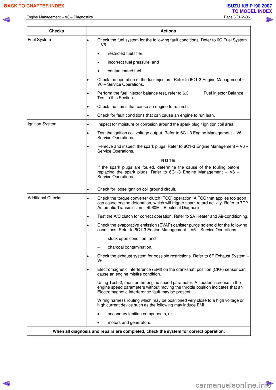
Checks Actions
Fuel System
• Check the fuel system for the following fault conditions. Refer to 6C Fuel System
– V6.
• restricted fuel filter,
• incorrect fuel pressure, and
• contaminated fuel.
• Check the operation of the fuel injectors. Refer to 6C1-3 Engine Management –
V6 – Service Operations.
• Perform the fuel injector balance test, refer to 6.3 Fuel Injector Balance
Test in this Section.
• Check the items that cause an engine to run rich.
• Check for fault conditions that can cause an engine to run lean.
Ignition System
• Inspect for moisture or corrosion around the spark plug / ignition coil area.
• Test the ignition coil voltage output. Refer to 6C1-3 Engine Management – V6 –
Service Operations.
• Remove and inspect the spark plugs. Refer to 6C1-3 Engine Management – V6 –
Service Operations.
NOTE
If the spark plugs are fouled, determine the cause of the fouling before
replacing the spark plugs. Refer to 6C1-3 Engine Management – V6 –
Service Operations.
• Check for loose ignition coil ground circuit.
Additional Checks
• Check the torque converter clutch (TCC) operation. A TCC that applies too soon
can cause engine detonation, which will trigger spark retard activity. Refer to 7C2
Automatic Transmission – 4L60E – Electrical Diagnosis.
• Test the A/C clutch for correct operation. Refer to 2A Heater and Air-conditioning.
• Check the evaporative emission (EVAP) canister purge solenoid for the following
conditions: Refer to 6C1-3 Engine Management – V6 – Service Operations.
− stuck open condition, and
− charcoal contamination.
• Check the exhaust system for possible restrictions. Refer to 6F Exhaust System –
V6.
• Electromagnetic interference (EMI) on the crankshaft position (CKP) sensor can
cause an engine misfire condition.
Using Tech 2, monitor the engine speed parameter. A sudden increase in the engine speed parameters without moving the throttle position indicates that an
Electromagnetic Interference fault may be present.
W iring harness routing which may be positioned very close to a high voltage or high current device such as the following may induce EMI:
• secondary ignition components, or
• motors and generators.
When all diagnosis and repairs are completed, check the system for correct operation.
BACK TO CHAPTER INDEX
TO MODEL INDEX
ISUZU KB P190 2007
Page 3316 of 6020
Engine Management – V6 – Diagnostics Page 6C1-2–38
Step Action Value(s) Yes No
3 1 Disconnect the fuel injector harness connector,
refer to 2.13 Fuel Rail Assembly, in 6C1-3 Engine
Management – V6 – Service Operations.
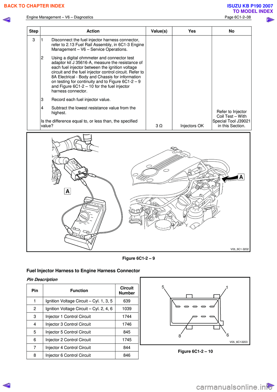
2 Using a digital ohmmeter and connector test adaptor kit J 35616-A, measure the resistance of
each fuel injector between the ignition voltage
circuit and the fuel injector control circuit. Refer to
8A Electrical - Body and Chassis for information
on testing for continuity and to Figure 6C1-2 – 9
and Figure 6C1-2 – 10 for the fuel injector
harness connector.
3 Record each fuel injector value.
4 Subtract the lowest resistance value from the highest.
Is the difference equal to, or less than, the specified
value? 3
Ω
Injectors OK Refer to Injector
Coil Test – W ith
Special Tool J39021 in this Section.
Figure 6C1-2 – 9
Fuel Injector Harness to Engine Harness Connector
Pin Description
Pin Function Circuit
Number
1 Ignition Voltage Circuit – Cyl. 1, 3, 5 639
2 Ignition Voltage Circuit – Cyl. 2, 4, 6 1039
3 Injector 1 Control Circuit 1744
4 Injector 3 Control Circuit 1746
5 Injector 5 Control Circuit 845
6 Injector 2 Control Circuit 1745
7 Injector 4 Control Circuit 844
8 Injector 6 Control Circuit 846
Figure 6C1-2 – 10
BACK TO CHAPTER INDEX
TO MODEL INDEX
ISUZU KB P190 2007
Page 3317 of 6020
Engine Management – V6 – Diagnostics Page 6C1-2–39
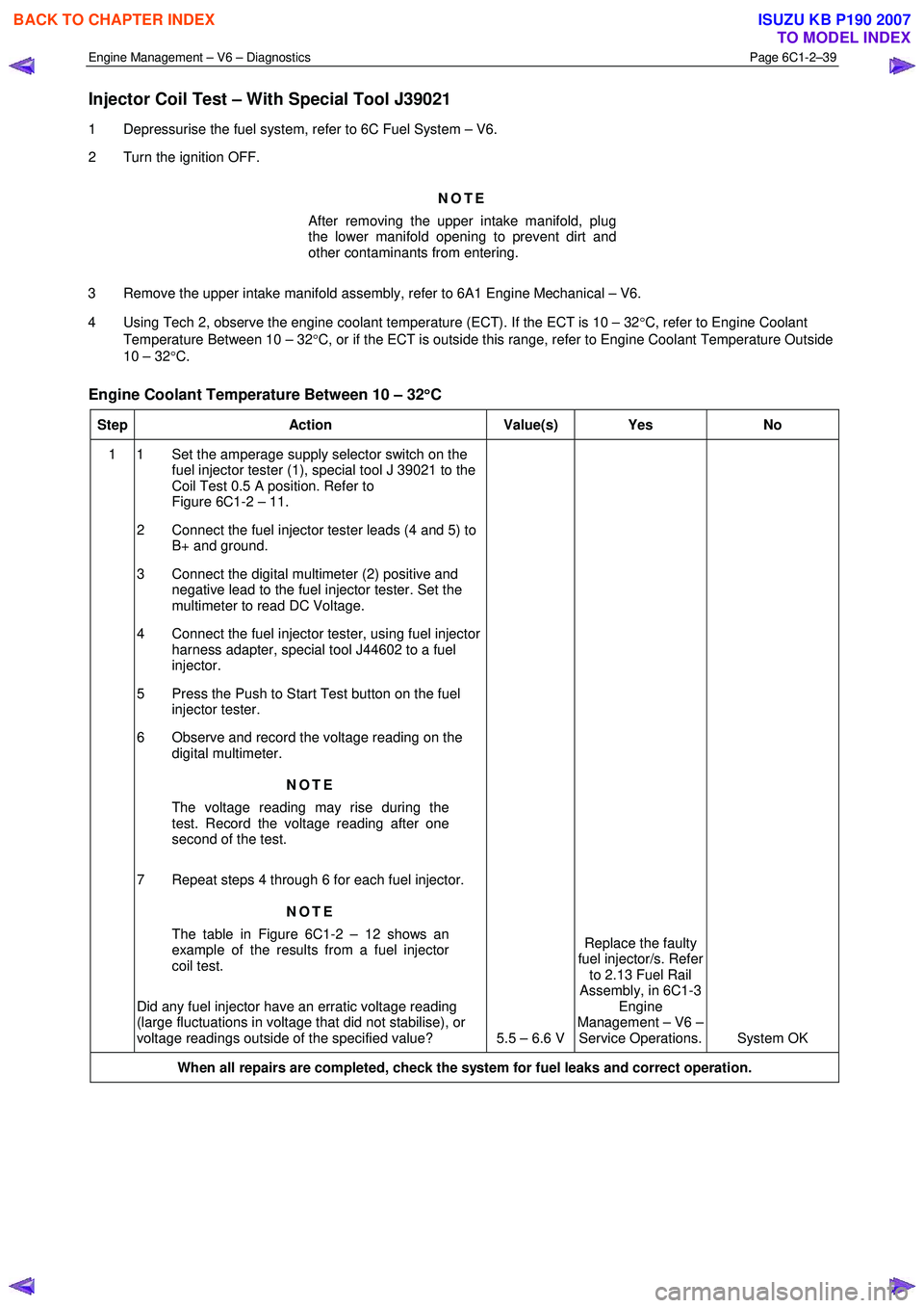
Injector Coil Test – With Special Tool J39021
1 Depressurise the fuel system, refer to 6C Fuel System – V6.
2 Turn the ignition OFF.
NOTE
After removing the upper intake manifold, plug
the lower manifold opening to prevent dirt and
other contaminants from entering.
3 Remove the upper intake manifold assembly, refer to 6A1 Engine Mechanical – V6.
4 Using Tech 2, observe the engine coolant temperature (ECT). If the ECT is 10 – 32 °C, refer to Engine Coolant
Temperature Between 10 – 32 °C, or if the ECT is outside this range, refer to Engine Coolant Temperature Outside
10 – 32 °C.
Engine Coolant Temperature Between 10 – 32 °
°°
°
C
Step Action Value(s) Yes No
1 1 Set the amperage supply selector switch on the
fuel injector tester (1), special tool J 39021 to the
Coil Test 0.5 A position. Refer to
Figure 6C1-2 – 11.
2 Connect the fuel injector tester leads (4 and 5) to B+ and ground.
3 Connect the digital multimeter (2) positive and negative lead to the fuel injector tester. Set the
multimeter to read DC Voltage.
4 Connect the fuel injector tester, using fuel injector harness adapter, special tool J44602 to a fuel
injector.
5 Press the Push to Start Test button on the fuel injector tester.
6 Observe and record the voltage reading on the digital multimeter.
NOTE
The voltage reading may rise during the
test. Record the voltage reading after one
second of the test.
7 Repeat steps 4 through 6 for each fuel injector. NOTE
The table in Figure 6C1-2 – 12 shows an
example of the results from a fuel injector
coil test.
Did any fuel injector have an erratic voltage reading
(large fluctuations in voltage that did not stabilise), or
voltage readings outside of the specified value? 5.5 – 6.6 V Replace the faulty
fuel injector/s. Refer to 2.13 Fuel Rail
Assembly, in 6C1-3 Engine
Management – V6 – Service Operations. System OK
When all repairs are completed, check the system for fuel leaks and correct operation.
BACK TO CHAPTER INDEX
TO MODEL INDEX
ISUZU KB P190 2007
Page 3318 of 6020

Engine Management – V6 – Diagnostics Page 6C1-2–40
Engine Coolant Temperature Outside 10 – 32°
°°
°
C
Step Action Value(s) Yes No
1 1 Set the amperage supply selector switch on the
fuel injector tester (1), special tool J 39021 to the
Coil Test 0.5 A position. Refer to
Figure 6C1-2 – 11.
2 Connect the fuel injector tester leads (4 and 5) to B+ and ground.
3 Connect the digital multimeter (2) positive and negative lead to the fuel injector tester. Set the
multimeter to read DC Voltage.
4 Connect the fuel injector tester, using injector harness adapter, special tool J44602 to a fuel
injector.
5 Press the Push to Start Test button on the fuel injector tester.
6 Observe and record the voltage reading on the digital multimeter.
NOTE
The voltage reading may rise during the
test. Record the voltage reading after one
second of the test.
7 Repeat steps 4 through 6 for each fuel injector.
8 Identify the highest voltage reading recorded from the six fuel injectors tested that is 9.5 V or less.
NOTE
Disregard those voltage readings that are
greater than 9.5 V. Voltage readings greater
than 9.5 V indicate a faulty fuel injector.
9 Subtract the remaining voltage readings recorded in Step 8, from the highest voltage reading.
Are any of the values recorded in Step 9 greater than
the specified value? 0.6 V
Go to Step 2 System OK
2 1 Replace any fuel injector that has any of the
following:
− a subtracted value exceeding 0.6 V,
− an initial reading greater than 9.5 V, and
− an erratic reading.
NOTE
The table in Figure 6C1-2 – 13 shows an
example of the results from a fuel injector
coil test.
Has the repair been completed? – System OK. –
When all repairs are completed, check the system for fuel leaks and correct operation.
BACK TO CHAPTER INDEX
TO MODEL INDEX
ISUZU KB P190 2007
Page 3320 of 6020
Engine Management – V6 – Diagnostics Page 6C1-2–42
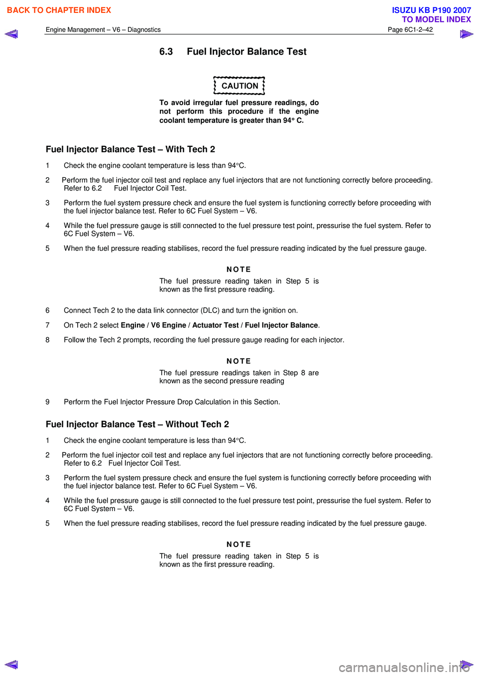
6.3 Fuel Injector Balance Test
To avoid irregular fuel pressure readings, do
not perform this procedure if the engine
coolant temperature is greater than 94 °
°°
°
C.
Fuel Injector Balance Test – With Tech 2
1 Check the engine coolant temperature is less than 94 °C.
2 Perform the fuel injector coil test and replace any fuel injectors that are not functioning correctly before proceeding. Refer to 6.2 Fuel Injector Coil Test.
3 Perform the fuel system pressure check and ensure the fuel system is functioning correctly before proceeding with the fuel injector balance test. Refer to 6C Fuel System – V6.
4 W hile the fuel pressure gauge is still connected to the fuel pressure test point, pressurise the fuel system. Refer to 6C Fuel System – V6.
5 W hen the fuel pressure reading stabilises, record the fuel pressure reading indicated by the fuel pressure gauge.
NOTE
The fuel pressure reading taken in Step 5 is
known as the first pressure reading.
6 Connect Tech 2 to the data link connector (DLC) and turn the ignition on.
7 On Tech 2 select Engine / V6 Engine / Actuator Test / Fuel Injector Balance .
8 Follow the Tech 2 prompts, recording the fuel pressure gauge reading for each injector.
NOTE
The fuel pressure readings taken in Step 8 are
known as the second pressure reading
9 Perform the Fuel Injector Pressure Drop Calculation in this Section.
Fuel Injector Balance Test – Without Tech 2
1 Check the engine coolant temperature is less than 94 °C.
2 Perform the fuel injector coil test and replace any fuel injectors that are not functioning correctly before proceeding. Refer to 6.2 Fuel Injector Coil Test.
3 Perform the fuel system pressure check and ensure the fuel system is functioning correctly before proceeding with the fuel injector balance test. Refer to 6C Fuel System – V6.
4 W hile the fuel pressure gauge is still connected to the fuel pressure test point, pressurise the fuel system. Refer to 6C Fuel System – V6.
5 W hen the fuel pressure reading stabilises, record the fuel pressure reading indicated by the fuel pressure gauge.
NOTE
The fuel pressure reading taken in Step 5 is
known as the first pressure reading.
BACK TO CHAPTER INDEX
TO MODEL INDEX
ISUZU KB P190 2007
Page 3321 of 6020
Engine Management – V6 – Diagnostics Page 6C1-2–43
6 Remove the upper intake manifold assembly, refer to 6A1 Engine Mechanical – V6.
NOTE
After removing the upper intake manifold, plug
the lower manifold opening to prevent dirt and
other contaminants from entering.
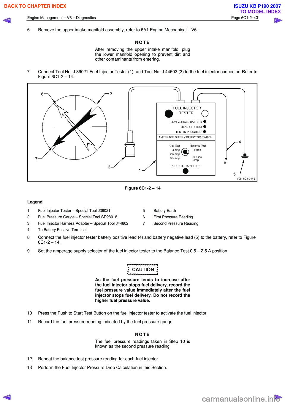
7 Connect Tool No. J 39021 Fuel Injector Tester (1), and Tool No. J 44602 (3) to the fuel injector connector. Refer to Figure 6C1-2 – 14.
Figure 6C1-2 – 14
Legend
1 Fuel Injector Tester – Special Tool J39021
2 Fuel Pressure Gauge – Special Tool SD28018
3 Fuel Injector Harness Adapter – Special Tool J44602
4 To Battery Positive Terminal 5 Battery Earth
6 First Pressure Reading
7 Second Pressure Reading
8 Connect the fuel injector tester battery positive lead (4) and battery negative lead (5) to the battery, refer to Figure 6C1-2 – 14.
9 Set the amperage supply selector of the fuel injector tester to the Balance Test 0.5 – 2.5 A position.
As the fuel pressure tends to increase after
the fuel injector stops fuel delivery, record the
fuel pressure value immediately after the fuel
injector stops fuel delivery. Do not record the
higher fuel pressure value.
10 Press the Push to Start Test Button on the fuel injector tester to activate the fuel injector.
11 Record the fuel pressure reading indicated by the fuel pressure gauge.
NOTE
The fuel pressure readings taken in Step 10 is
known as the second pressure reading
12 Repeat the balance test pressure reading for each fuel injector.
13 Perform the Fuel Injector Pressure Drop Calculation in this Section.
BACK TO CHAPTER INDEX
TO MODEL INDEX
ISUZU KB P190 2007
Page 3322 of 6020
Engine Management – V6 – Diagnostics Page 6C1-2–44
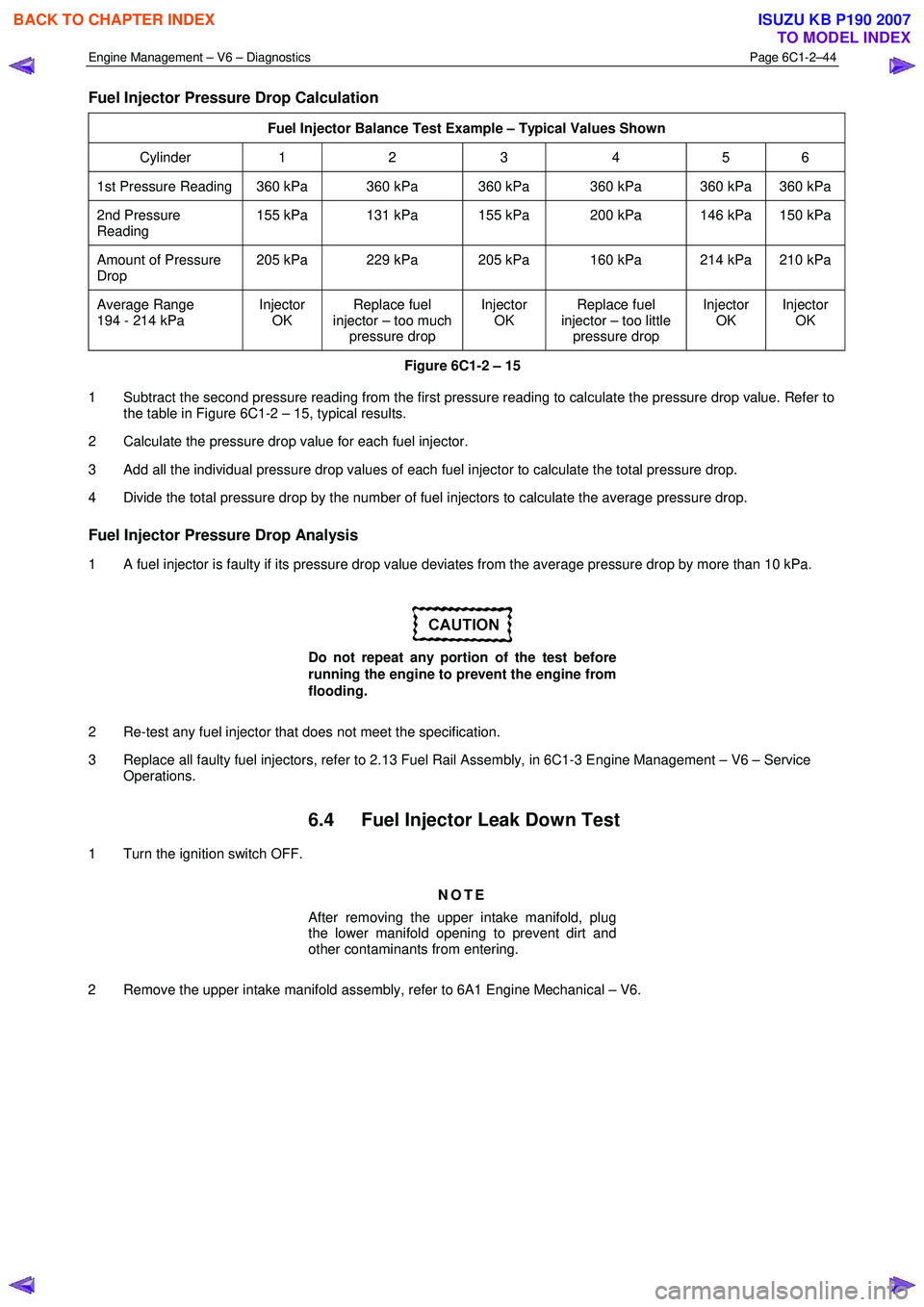
Fuel Injector Pressure Drop Calculation
Fuel Injector Balance Test Example – Typical Values Shown
Cylinder 1 2 3 4 5 6
1st Pressure Reading 360 kPa 360 kPa 360 kPa 360 kPa 360 kPa 360 kPa
2nd Pressure
Reading 155 kPa 131 kPa 155 kPa 200 kPa 146 kPa 150 kPa
Amount of Pressure
Drop 205 kPa 229 kPa 205 kPa 160 kPa 214 kPa 210 kPa
Average Range
194 - 214 kPa Injector
OK Replace fuel
injector – too much pressure drop Injector
OK Replace fuel
injector – too little pressure drop Injector
OK Injector
OK
Figure 6C1-2 – 15
1 Subtract the second pressure reading from the first pressure reading to calculate the pressure drop value. Refer to the table in Figure 6C1-2 – 15, typical results.
2 Calculate the pressure drop value for each fuel injector.
3 Add all the individual pressure drop values of each fuel injector to calculate the total pressure drop.
4 Divide the total pressure drop by the number of fuel injectors to calculate the average pressure drop.
Fuel Injector Pressure Drop Analysis
1 A fuel injector is faulty if its pressure drop value deviates from the average pressure drop by more than 10 kPa.
Do not repeat any portion of the test before
running the engine to prevent the engine from
flooding.
2 Re-test any fuel injector that does not meet the specification.
3 Replace all faulty fuel injectors, refer to 2.13 Fuel Rail Assembly, in 6C1-3 Engine Management – V6 – Service Operations.
6.4 Fuel Injector Leak Down Test
1 Turn the ignition switch OFF.
NOTE
After removing the upper intake manifold, plug
the lower manifold opening to prevent dirt and
other contaminants from entering.
2 Remove the upper intake manifold assembly, refer to 6A1 Engine Mechanical – V6.
BACK TO CHAPTER INDEX
TO MODEL INDEX
ISUZU KB P190 2007
Page 3324 of 6020
Engine Management – V6 – Diagnostics Page 6C1-2–46
6.5 Alcohol / Contaminants in Fuel
Diagnosis
Description
W ater contamination in the fuel system may cause driveability conditions such as hesitation, stalling, no start, or
misfires in one or more cylinders. W ater may collect near a single fuel injector at the lowest point in the fuel rail, and
cause a misfire in that cylinder. If the fuel system is contaminated with water, inspect the fuel system components for
rust, or deterioration.
Alcohol (e.g. Ethanol) concentrations more than 10% in the fuel can be detrimental to fuel system components. Alcohol
contamination may cause fuel system corrosion, deterioration of rubber components, and subsequent fuel filter
restriction. Fuel contaminated with alcohol may cause driveability conditions such as hesitation, lack of power, stalling,
or no start. Some types of alcohol are more detrimental to fuel system components than others.
Alcohol in Fuel Testing Procedure
NOTE
The procedures detailed are not intended to be
accurate but rather, indicative of a contamination
situation.
The fuel sample should be drawn from the bottom of the tank so that any water present in the tank will be detected. The
sample should be bright and clear. If alcohol contamination is suspected, then use the following procedure to test the
fuel quality.
• Using a 100 ml graduated cylinder with 1 ml marks, fill the cylinder with fuel to the 90 ml mark.
• Add 10 ml of water to bring the total fluid volume to 100 ml and install a stopper.
• Shake the cylinder vigorously for 10 – 15 seconds.
• Carefully loosen the stopper to release the pressure.
• Re-install the stopper and shake the cylinder vigorously again for 10 – 15 seconds.
• Put the cylinder on a level surface for approximately 5 minutes to allow adequate liquid separation.
If alcohol is present in the fuel, the volume of the lower layer, that now contains both alcohol and water, will be more
than 10 ml. For example, if the volume of the lower layer is increased to 15 ml, this indicates at least 5 percent alcohol in
the fuel. The actual amount of alcohol may be somewhat more because this procedure does not extract all of the
alcohol from the fuel. To obtain an accurate determination of the amount of alcohol contamination in a given fuel sample,
then professional analysis should be sought.
Particulate Contaminants in Fuel Testing Procedure
The fuel sample should be drawn from the bottom of the tank so that any contaminants present in the tank will be
detected. The sample should be bright and clear. If the sample appears cloudy or contaminated with water as indicated
by a water layer at the bottom of the sample, use the following procedure to diagnose the fuel.
• Using an approved fuel container, draw approximately 0.5 litre of fuel.
• Place the cylinder on a level surface for approximately 5 minutes to allow settling of the particulate contamination.
Particulate contamination will show up in various shapes and colours. Sand will typically be identified by a white or light
brown crystals. Rubber will appear as black and irregular particles. If particles are found, clean the entire fuel system
thoroughly. Refer to 6C Fuel System – V6.
6.6 Crankshaft Position (CKP) System
Variation Learn Procedure
Description
The crankshaft position system variation learn feature is carried out automatically on the HFV6 engine under decel with
fuel cut. The road speed and duration of the self-learn process varies with different vehicle equipment levels such as
transmission, final drive ratio etc.
The variation learn procedure cannot be over-written, nor can it be accessed with Tech 2.
BACK TO CHAPTER INDEX
TO MODEL INDEX
ISUZU KB P190 2007