2007 ISUZU KB P190 ECO mode
[x] Cancel search: ECO modePage 3368 of 6020

Engine Management – V6 – Diagnostics Page 6C1-2–90
Step Action Yes No
2 NOTE
• DTC P0133 is for bank 1 sensor 1 and DTC P0153 is
for bank 2 sensor 1.
• DTC P0132 causes DTC P0153 to set. If DTC P0132
is set with DTC P0153, refer to 7.10 DTC
P0130, P0131, P0132, P0135, P0137, P0138, P0140,
P0141, P0150 P0151, P0152, P0155, P0157, P0158,
P0160, P0161, P2243, P2247, P2270, P2271, P2272,
P2273, P2297 or P2298 in this Section.
• Inspect the heated oxygen sensor (HO2S) for being
secure before proceeding with this DTC. A sensor that
is loose could cause this DTC to set.
1 Start engine and allow to reach operating temperature.
2 Observe the diagnostic trouble code (DTC) information with Tech 2.
Did DTC P0133 and / or DTC P0153 fail this ignition cycle? Go to Step 4 Go to Step 3
3 1 Observe the Freeze Frame / Failure Records for this DTC.
2 Turn OFF the ignition for 30 seconds.
3 Start the engine.
4 Operate the vehicle within the Conditions for Running the DTC. You may also operate the vehicle within the conditions that you
observed from the Freeze Frame / Failure Records.
Did the DTC fail this ignition? Go to Step 4 Go to Additional
Information in this DTC
4 Did DTC P0133 and DTC P0153 fail this ignition cycle? Go to Step 7 Go to Step 5
5 1 Inspect for an exhaust leak near the HO2S. Refer to 6F Exhaust
System – V6. After you inspect the exhaust system, return to
this diagnostic.
Did you find and correct the condition? Go to Step 8 Go to Step 6
6 1 Inspect or test for the following conditions:
• Inspect that the HO2S is securely installed.
• Inspect for corrosion on the HO2S terminals.
• Inspect the terminal tension at the HO2S and at the
engine control module (ECM). Refer to 8A Electrical-Body
and Chassis.
• Inspect the HO2S wiring for damage.
Did you find and correct the condition? Go to Step 8 Go to Step 7
BACK TO CHAPTER INDEX
TO MODEL INDEX
ISUZU KB P190 2007
Page 3369 of 6020
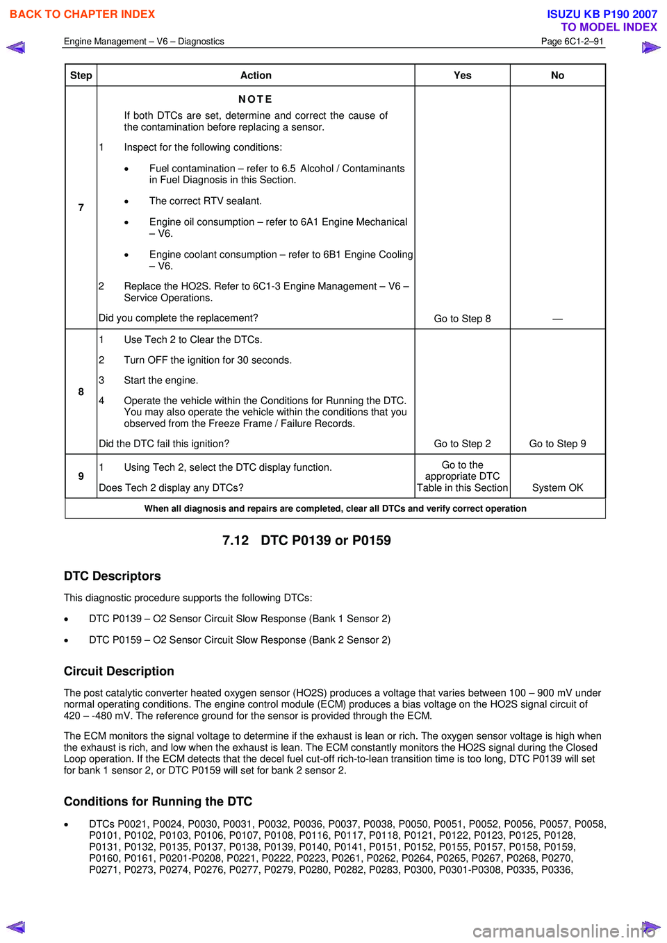
Engine Management – V6 – Diagnostics Page 6C1-2–91
Step Action Yes No
7 NOTE
If both DTCs are set, determine and correct the cause of
the contamination before replacing a sensor.
1 Inspect for the following conditions:
• Fuel contamination – refer to 6.5 Alcohol / Contaminants
in Fuel Diagnosis in this Section.
• The correct RTV sealant.
• Engine oil consumption – refer to 6A1 Engine Mechanical
– V6.
• Engine coolant consumption – refer to 6B1 Engine Cooling
– V6.
2 Replace the HO2S. Refer to 6C1-3 Engine Management – V6 – Service Operations.
Did you complete the replacement? Go to Step 8 —
8 1 Use Tech 2 to Clear the DTCs.
2 Turn OFF the ignition for 30 seconds.
3 Start the engine.
4 Operate the vehicle within the Conditions for Running the DTC. You may also operate the vehicle within the conditions that you
observed from the Freeze Frame / Failure Records.
Did the DTC fail this ignition? Go to Step 2 Go to Step 9
9 1 Using Tech 2, select the DTC display function.
Does Tech 2 display any DTCs? Go to the
appropriate DTC
Table in this Section System OK
When all diagnosis and repairs are completed, clear all DTCs and verify correct operation
7.12 DTC P0139 or P0159
DTC Descriptors
This diagnostic procedure supports the following DTCs:
• DTC P0139 – O2 Sensor Circuit Slow Response (Bank 1 Sensor 2)
• DTC P0159 – O2 Sensor Circuit Slow Response (Bank 2 Sensor 2)
Circuit Description
The post catalytic converter heated oxygen sensor (HO2S) produces a voltage that varies between 100 – 900 mV under
normal operating conditions. The engine control module (ECM) produces a bias voltage on the HO2S signal circuit of
420 – -480 mV. The reference ground for the sensor is provided through the ECM.
The ECM monitors the signal voltage to determine if the exhaust is lean or rich. The oxygen sensor voltage is high when
the exhaust is rich, and low when the exhaust is lean. The ECM constantly monitors the HO2S signal during the Closed
Loop operation. If the ECM detects that the decel fuel cut-off rich-to-lean transition time is too long, DTC P0139 will set
for bank 1 sensor 2, or DTC P0159 will set for bank 2 sensor 2.
Conditions for Running the DTC
• DTCs P0021, P0024, P0030, P0031, P0032, P0036, P0037, P0038, P0050, P0051, P0052, P0056, P0057, P0058,
P0101, P0102, P0103, P0106, P0107, P0108, P0116, P0117, P0118, P0121, P0122, P0123, P0125, P0128,
P0131, P0132, P0135, P0137, P0138, P0139, P0140, P0141, P0151, P0152, P0155, P0157, P0158, P0159,
P0160, P0161, P0201-P0208, P0221, P0222, P0223, P0261, P0262, P0264, P0265, P0267, P0268, P0270,
P0271, P0273, P0274, P0276, P0277, P0279, P0280, P0282, P0283, P0300, P0301-P0308, P0335, P0336,
BACK TO CHAPTER INDEX
TO MODEL INDEX
ISUZU KB P190 2007
Page 3370 of 6020
Engine Management – V6 – Diagnostics Page 6C1-2–92
P0340, P0341, P0345, P0346, P0351-P0358, P0365, P0366, P0390, P0391, P0442, P0443, P0446, P0449,
P0453, P0454, P0455, P0458, P0459, and P0496 are not set.
• The ECT Sensor parameter is more than 66° C.
• The Vehicle Speed Sensor parameter is between 5 – 180 km/h.
• The calculated catalytic converter temperature is more than 520° C.
• DTC P0139 or P0159 runs continuously once the above conditions are met.
Conditions for Setting the DTC
• The ECM detects that the decel fuel cut-off and rich-to-lean transition time has exceeded 1 second.
Action Taken When the DTC Sets
• The ECM illuminates the malfunction indicator lamp (MIL) on the second consecutive ignition cycle that the
diagnostic runs and fails.
• The ECM records the operating conditions at the time the diagnostic fails. The first time the diagnostic fails, the
control module stores this information in the Failure Records. If the diagnostic reports a failure on the second
consecutive ignition cycle, the control module records the operating conditions at the time of the failure.
• The ECM writes the operating conditions to the Freeze Frame and updates the Failure Records.
Conditions for Clearing the MIL/DTC
• The ECM turns OFF the malfunction indicator lamp (MIL) after three consecutive ignition cycles that the diagnostic
runs and does not fail.
• A current DTC, Last Test Failed, clears when the diagnostic runs and passes.
• A history DTC clears after 40 consecutive warm-up cycles, if no failures are reported by this or any other emission
related diagnostic.
• Use Tech 2 to clear the MIL and the DTC.
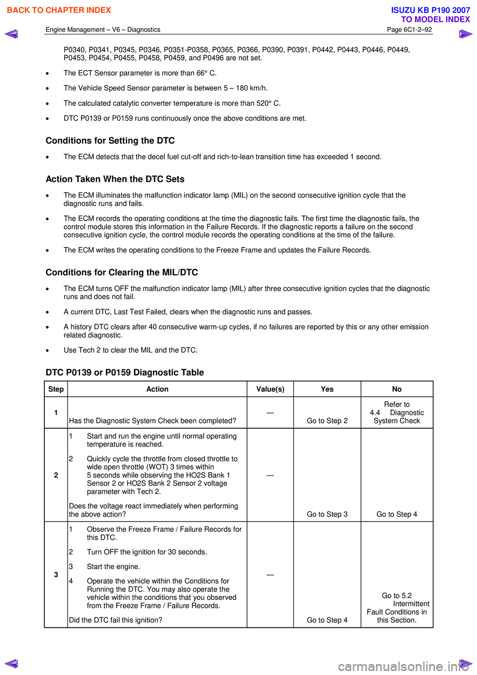
DTC P0139 or P0159 Diagnostic Table
Step Action Value(s) Yes No
1
Has the Diagnostic System Check been completed? —
Go to Step 2 Refer to
4.4 Diagnostic System Check
2 1 Start and run the engine until normal operating
temperature is reached.
2 Quickly cycle the throttle from closed throttle to wide open throttle (W OT) 3 times within
5 seconds while observing the HO2S Bank 1
Sensor 2 or HO2S Bank 2 Sensor 2 voltage
parameter with Tech 2.
Does the voltage react immediately when performing
the above action? —
Go to Step 3 Go to Step 4
3 1 Observe the Freeze Frame / Failure Records for
this DTC.
2 Turn OFF the ignition for 30 seconds.
3 Start the engine.
4 Operate the vehicle within the Conditions for Running the DTC. You may also operate the
vehicle within the conditions that you observed
from the Freeze Frame / Failure Records.
Did the DTC fail this ignition? —
Go to Step 4 Go to 5.2
Intermittent Fault Conditions in this Section.
BACK TO CHAPTER INDEX
TO MODEL INDEX
ISUZU KB P190 2007
Page 3372 of 6020
Engine Management – V6 – Diagnostics Page 6C1-2–94
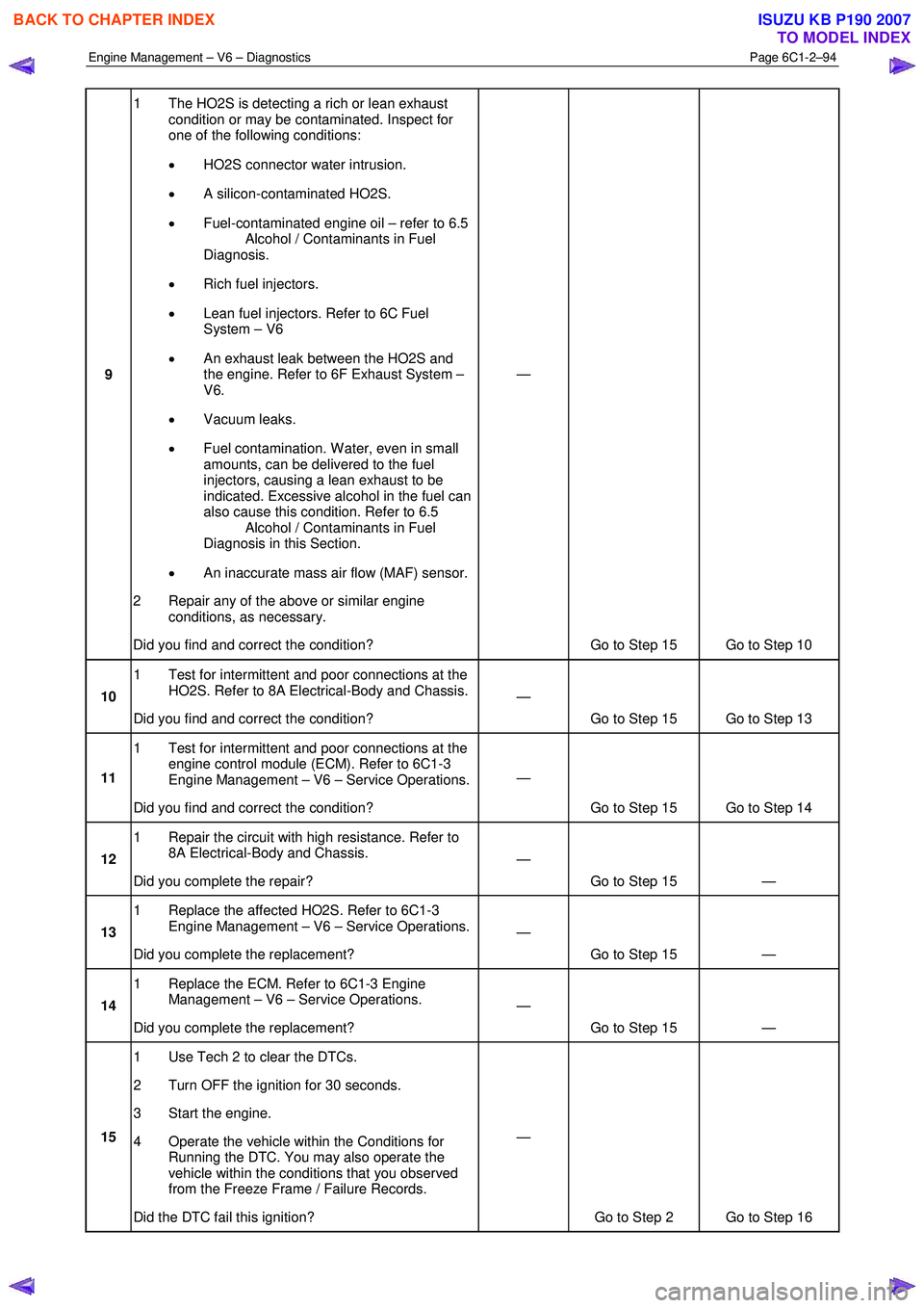
9 1 The HO2S is detecting a rich or lean exhaust
condition or may be contaminated. Inspect for
one of the following conditions:
• HO2S connector water intrusion.
• A silicon-contaminated HO2S.
• Fuel-contaminated engine oil – refer to 6.5
Alcohol / Contaminants in Fuel
Diagnosis.
• Rich fuel injectors.
• Lean fuel injectors. Refer to 6C Fuel
System – V6
• An exhaust leak between the HO2S and
the engine. Refer to 6F Exhaust System –
V6.
• Vacuum leaks.
• Fuel contamination. W ater, even in small
amounts, can be delivered to the fuel
injectors, causing a lean exhaust to be
indicated. Excessive alcohol in the fuel can
also cause this condition. Refer to 6.5
Alcohol / Contaminants in Fuel
Diagnosis in this Section.
• An inaccurate mass air flow (MAF) sensor.
2 Repair any of the above or similar engine conditions, as necessary.
Did you find and correct the condition? —
Go to Step 15 Go to Step 10
10 1 Test for intermittent and poor connections at the
HO2S. Refer to 8A Electrical-Body and Chassis.
Did you find and correct the condition? —
Go to Step 15 Go to Step 13
11 1 Test for intermittent and poor connections at the
engine control module (ECM). Refer to 6C1-3
Engine Management – V6 – Service Operations.
Did you find and correct the condition? —
Go to Step 15 Go to Step 14
12 1 Repair the circuit with high resistance. Refer to
8A Electrical-Body and Chassis.
Did you complete the repair? —
Go to Step 15 —
13 1 Replace the affected HO2S. Refer to 6C1-3
Engine Management – V6 – Service Operations.
Did you complete the replacement? —
Go to Step 15 —
14 1 Replace the ECM. Refer to 6C1-3 Engine
Management – V6 – Service Operations.
Did you complete the replacement? —
Go to Step 15 —
15 1 Use Tech 2 to clear the DTCs.
2 Turn OFF the ignition for 30 seconds.
3 Start the engine.
4 Operate the vehicle within the Conditions for Running the DTC. You may also operate the
vehicle within the conditions that you observed
from the Freeze Frame / Failure Records.
Did the DTC fail this ignition? —
Go to Step 2 Go to Step 16
BACK TO CHAPTER INDEX
TO MODEL INDEX
ISUZU KB P190 2007
Page 3373 of 6020
Engine Management – V6 – Diagnostics Page 6C1-2–95
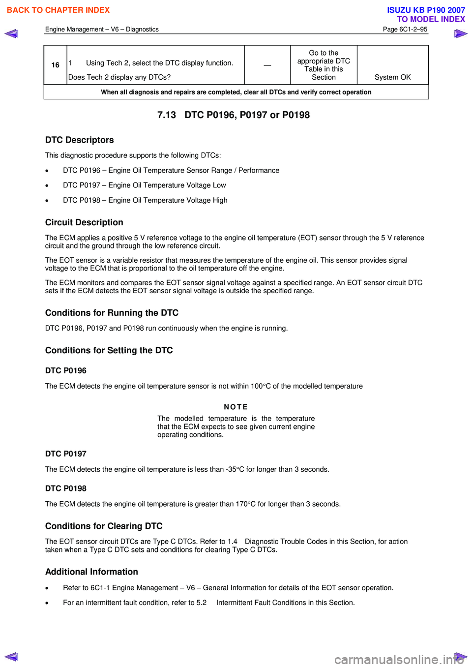
16 1 Using Tech 2, select the DTC display function.
Does Tech 2 display any DTCs? —
Go to the
appropriate DTC Table in this Section System OK
When all diagnosis and repairs are completed, clear all DTCs and verify correct operation
7.13 DTC P0196, P0197 or P0198
DTC Descriptors
This diagnostic procedure supports the following DTCs:
• DTC P0196 – Engine Oil Temperature Sensor Range / Performance
• DTC P0197 – Engine Oil Temperature Voltage Low
• DTC P0198 – Engine Oil Temperature Voltage High
Circuit Description
The ECM applies a positive 5 V reference voltage to the engine oil temperature (EOT) sensor through the 5 V reference
circuit and the ground through the low reference circuit.
The EOT sensor is a variable resistor that measures the temperature of the engine oil. This sensor provides signal
voltage to the ECM that is proportional to the oil temperature off the engine.
The ECM monitors and compares the EOT sensor signal voltage against a specified range. An EOT sensor circuit DTC
sets if the ECM detects the EOT sensor signal voltage is outside the specified range.
Conditions for Running the DTC
DTC P0196, P0197 and P0198 run continuously when the engine is running.
Conditions for Setting the DTC
DTC P0196
The ECM detects the engine oil temperature sensor is not within 100 °C of the modelled temperature
NOTE
The modelled temperature is the temperature
that the ECM expects to see given current engine
operating conditions.
DTC P0197
The ECM detects the engine oil temperature is less than -35 °C for longer than 3 seconds.
DTC P0198
The ECM detects the engine oil temperature is greater than 170 °C for longer than 3 seconds.
Conditions for Clearing DTC
The EOT sensor circuit DTCs are Type C DTCs. Refer to 1.4 Diagnostic Trouble Codes in this Section, for action
taken when a Type C DTC sets and conditions for clearing Type C DTCs.
Additional Information
• Refer to 6C1-1 Engine Management – V6 – General Information for details of the EOT sensor operation.
• For an intermittent fault condition, refer to 5.2 Intermittent Fault Conditions in this Section.
BACK TO CHAPTER INDEX
TO MODEL INDEX
ISUZU KB P190 2007
Page 3374 of 6020
Engine Management – V6 – Diagnostics Page 6C1-2–96
• Since fault condition in a wiring connector may trigger DTCs, always test the connectors related to this diagnostic
procedure for shorted terminals or poor wiring connection before replacing any component. Refer to 8A Electrical -
Body and Chassis for information on electrical fault diagnosis.
• To assist diagnosis, refer to 3 W iring Diagrams and Connector Charts in this Section, for the system wiring
diagram and connector charts.
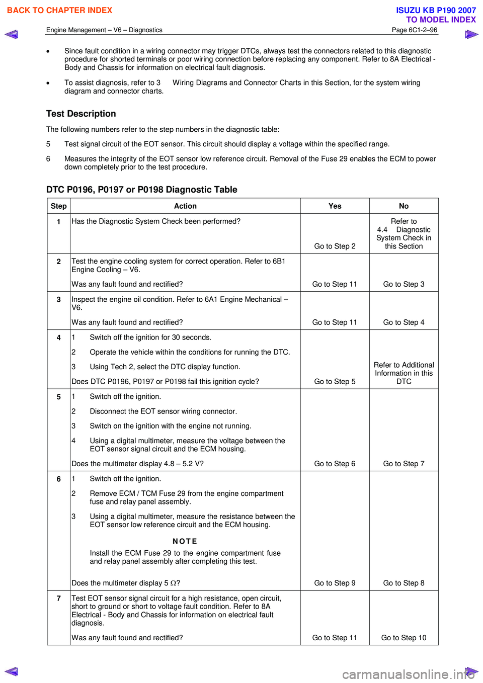
Test Description
The following numbers refer to the step numbers in the diagnostic table:
5 Test signal circuit of the EOT sensor. This circuit should display a voltage within the specified range.
6 Measures the integrity of the EOT sensor low reference circuit. Removal of the Fuse 29 enables the ECM to power down completely prior to the test procedure.
DTC P0196, P0197 or P0198 Diagnostic Table
Step Action Yes No
1 Has the Diagnostic System Check been performed?
Go to Step 2 Refer to
4.4 Diagnostic
System Check in this Section
2 Test the engine cooling system for correct operation. Refer to 6B1
Engine Cooling – V6.
W as any fault found and rectified? Go to Step 11 Go to Step 3
3 Inspect the engine oil condition. Refer to 6A1 Engine Mechanical –
V6.
W as any fault found and rectified? Go to Step 11 Go to Step 4
4 1 Switch off the ignition for 30 seconds.
2 Operate the vehicle within the conditions for running the DTC.
3 Using Tech 2, select the DTC display function.
Does DTC P0196, P0197 or P0198 fail this ignition cycle? Go to Step 5 Refer to Additional
Information in this DTC
5 1 Switch off the ignition.
2 Disconnect the EOT sensor wiring connector.
3 Switch on the ignition with the engine not running.
4 Using a digital multimeter, measure the voltage between the EOT sensor signal circuit and the ECM housing.
Does the multimeter display 4.8 – 5.2 V? Go to Step 6 Go to Step 7
6 1 Switch off the ignition.
2 Remove ECM / TCM Fuse 29 from the engine compartment fuse and relay panel assembly.
3 Using a digital multimeter, measure the resistance between the EOT sensor low reference circuit and the ECM housing.
NOTE
Install the ECM Fuse 29 to the engine compartment fuse
and relay panel assembly after completing this test.
Does the multimeter display 5 Ω? Go to Step 9 Go to Step 8
7 Test EOT sensor signal circuit for a high resistance, open circuit,
short to ground or short to voltage fault condition. Refer to 8A
Electrical - Body and Chassis for information on electrical fault
diagnosis.
W as any fault found and rectified? Go to Step 11 Go to Step 10
BACK TO CHAPTER INDEX
TO MODEL INDEX
ISUZU KB P190 2007
Page 3375 of 6020
Engine Management – V6 – Diagnostics Page 6C1-2–97
Step Action Yes
No
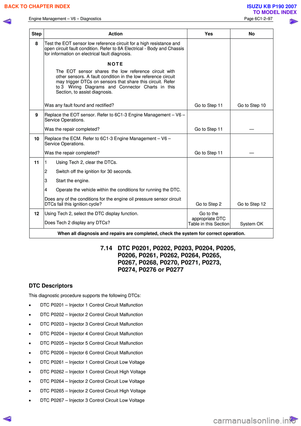
8 Test the EOT sensor low reference circuit for a high resistance and
open circuit fault condition. Refer to 8A Electrical - Body and Chassis
for information on electrical fault diagnosis.
NOTE
The EOT sensor shares the low reference circuit with
other sensors. A fault condition in the low reference circuit
may trigger DTCs on sensors that share this circuit. Refer
to 3 W iring Diagrams and Connector Charts in this
Section, to assist diagnosis.
W as any fault found and rectified? Go to Step 11 Go to Step 10
9 Replace the EOT sensor. Refer to 6C1-3 Engine Management – V6 –
Service Operations.
W as the repair completed? Go to Step 11 —
10 Replace the ECM. Refer to 6C1-3 Engine Management – V6 –
Service Operations.
W as the repair completed? Go to Step 11 —
11 1 Using Tech 2, clear the DTCs.
2 Switch off the ignition for 30 seconds.
3 Start the engine.
4 Operate the vehicle within the conditions for running the DTC.
Does any of the conditions for the engine oil pressure sensor circuit
DTCs fail this ignition cycle? Go to Step 2 Go to Step 12
12 Using Tech 2, select the DTC display function.
Does Tech 2 display any DTCs? Go to the
appropriate DTC
Table in this Section System OK
When all diagnosis and repairs are completed, check the system for correct operation.
7.14 DTC P0201, P0202, P0203, P0204, P0205,
P0206, P0261, P0262, P0264, P0265,
P0267, P0268, P0270, P0271, P0273,
P0274, P0276 or P0277
DTC Descriptors
This diagnostic procedure supports the following DTCs:
• DTC P0201 – Injector 1 Control Circuit Malfunction
• DTC P0202 – Injector 2 Control Circuit Malfunction
• DTC P0203 – Injector 3 Control Circuit Malfunction
• DTC P0204 – Injector 4 Control Circuit Malfunction
• DTC P0205 – Injector 5 Control Circuit Malfunction
• DTC P0206 – Injector 6 Control Circuit Malfunction
• DTC P0261 – Injector 1 Control Circuit Low Voltage
• DTC P0262 – Injector 1 Control Circuit High Voltage
• DTC P0264 – Injector 2 Control Circuit Low Voltage
• DTC P0265 – Injector 2 Control Circuit High Voltage
• DTC P0267 – Injector 3 Control Circuit Low Voltage
BACK TO CHAPTER INDEX
TO MODEL INDEX
ISUZU KB P190 2007
Page 3377 of 6020
Engine Management – V6 – Diagnostics Page 6C1-2–99
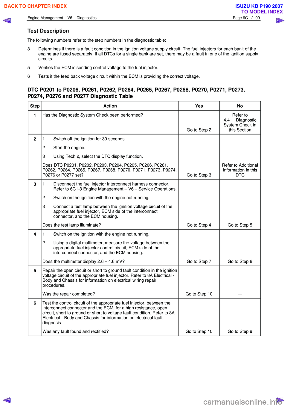
Test Description
The following numbers refer to the step numbers in the diagnostic table:
3 Determines if there is a fault condition in the ignition voltage supply circuit. The fuel injectors for each bank of the engine are fused separately. If all DTCs for a single bank are set, there may be a fault in one of the ignition supply
circuits.
5 Verifies the ECM is sending control voltage to the fuel injector.
6 Tests if the feed back voltage circuit within the ECM is providing the correct voltage.
DTC P0201 to P0206, P0261, P0262, P0264, P0265, P0267, P0268, P0270, P0271, P0273,
P0274, P0276 and P0277 Diagnostic Table
Step Action Yes No
1 Has the Diagnostic System Check been performed?
Go to Step 2 Refer to
4.4 Diagnostic
System Check in this Section
2 1 Switch off the ignition for 30 seconds.
2 Start the engine.
3 Using Tech 2, select the DTC display function.
Does DTC P0201, P0202, P0203, P0204, P0205, P0206, P0261,
P0262, P0264, P0265, P0267, P0268, P0270, P0271, P0273, P0274,
P0276 or P0277 set? Go to Step 3 Refer to Additional
Information in this DTC
3 1 Disconnect the fuel injector interconnect harness connector.
Refer to 6C1-3 Engine Management – V6 – Service Operations.
2 Switch on the ignition with the engine not running.
3 Connect a test lamp between the ignition voltage circuit of the appropriate fuel injector, ECM side of the interconnect
connector, and the ECM housing.
Does the test lamp illuminate? Go to Step 4 Go to Step 5
4 1 Switch on the ignition with the engine not running.
2 Using a digital multimeter, measure the voltage between the appropriate fuel injector control circuit, ECM side of the
interconnect connector, and the ECM housing.
Does the multimeter display 2.6 – 4.6 mV? Go to Step 7 Go to Step 6
5 Repair the open circuit or short to ground fault condition in the ignition
voltage circuit of the appropriate fuel injector. Refer to 8A Electrical -
Body and Chassis for information on electrical wiring repair
procedures.
W as the repair completed? Go to Step 10 —
6 Test the control circuit of the appropriate fuel injector, between the
interconnect connector and the ECM, for a high resistance, open
circuit, short to ground or short to voltage fault condition. Refer to 8A
Electrical - Body and Chassis for information on electrical fault
diagnosis.
W as any fault found and rectified? Go to Step 10 Go to Step 9
BACK TO CHAPTER INDEX
TO MODEL INDEX
ISUZU KB P190 2007