2007 ISUZU KB P190 ECO mode
[x] Cancel search: ECO modePage 3270 of 6020
Engine Management – V6 – General Information Page 6C1-1–28
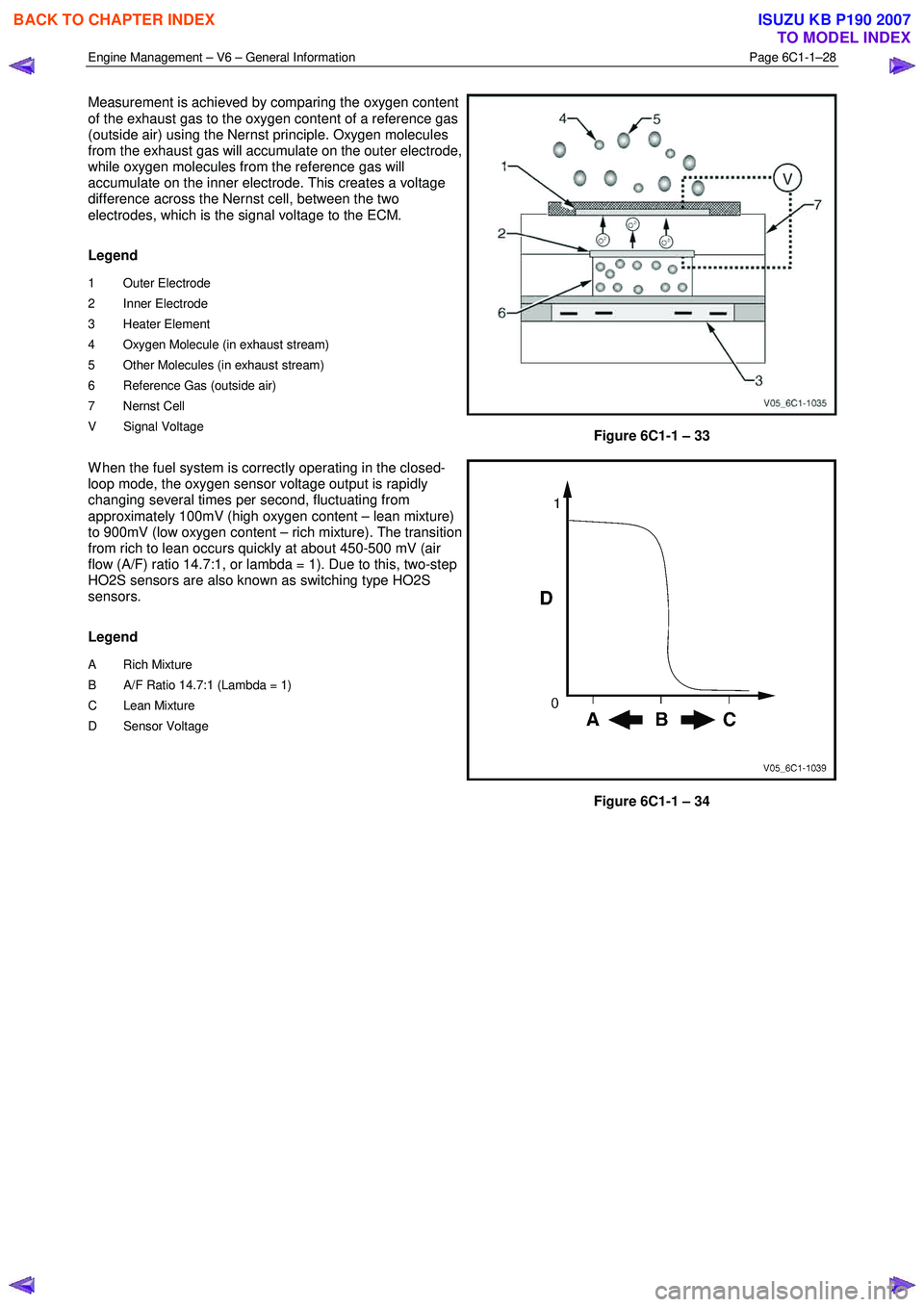
Measurement is achieved by comparing the oxygen content
of the exhaust gas to the oxygen content of a reference gas
(outside air) using the Nernst principle. Oxygen molecules
from the exhaust gas will accumulate on the outer electrode,
while oxygen molecules from the reference gas will
accumulate on the inner electrode. This creates a voltage
difference across the Nernst cell, between the two
electrodes, which is the signal voltage to the ECM.
Legend
1 Outer Electrode
2 Inner Electrode
3 Heater Element
4 Oxygen Molecule (in exhaust stream)
5 Other Molecules (in exhaust stream)
6 Reference Gas (outside air)
7 Nernst Cell
V Signal Voltage
Figure 6C1-1 – 33
W hen the fuel system is correctly operating in the closed-
loop mode, the oxygen sensor voltage output is rapidly
changing several times per second, fluctuating from
approximately 100mV (high oxygen content – lean mixture)
to 900mV (low oxygen content – rich mixture). The transition
from rich to lean occurs quickly at about 450-500 mV (air
flow (A/F) ratio 14.7:1, or lambda = 1). Due to this, two-step
HO2S sensors are also known as switching type HO2S
sensors.
Legend
A Rich Mixture
B A/F Ratio 14.7:1 (Lambda = 1)
C Lean Mixture
D Sensor Voltage
Figure 6C1-1 – 34
BACK TO CHAPTER INDEX
TO MODEL INDEX
ISUZU KB P190 2007
Page 3273 of 6020
Engine Management – V6 – General Information Page 6C1-1–31
4.15 Ignition Coil and Spark Plug
Long-life platinum tip spark plugs are used which, along with
the ignition coil spark plug boot and spring, require
replacement at 100,000 kilometre service intervals. The
spark plugs, featuring a J-gap and a conical seat, do not
require inspection between services, and must not be re-
gapped.
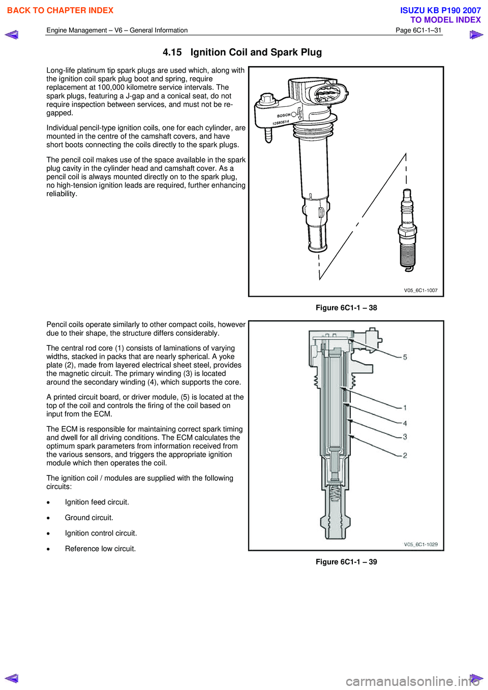
Individual pencil-type ignition coils, one for each cylinder, are
mounted in the centre of the camshaft covers, and have
short boots connecting the coils directly to the spark plugs.
The pencil coil makes use of the space available in the spark
plug cavity in the cylinder head and camshaft cover. As a
pencil coil is always mounted directly on to the spark plug,
no high-tension ignition leads are required, further enhancing
reliability.
Figure 6C1-1 – 38
Pencil coils operate similarly to other compact coils, however
due to their shape, the structure differs considerably.
The central rod core (1) consists of laminations of varying
widths, stacked in packs that are nearly spherical. A yoke
plate (2), made from layered electrical sheet steel, provides
the magnetic circuit. The primary winding (3) is located
around the secondary winding (4), which supports the core.
A printed circuit board, or driver module, (5) is located at the
top of the coil and controls the firing of the coil based on
input from the ECM.
The ECM is responsible for maintaining correct spark timing
and dwell for all driving conditions. The ECM calculates the
optimum spark parameters from information received from
the various sensors, and triggers the appropriate ignition
module which then operates the coil.
The ignition coil / modules are supplied with the following
circuits:
• Ignition feed circuit.
• Ground circuit.
• Ignition control circuit.
• Reference low circuit.
Figure 6C1-1 – 39
BACK TO CHAPTER INDEX
TO MODEL INDEX
ISUZU KB P190 2007
Page 3276 of 6020
Engine Management – V6 – General Information Page 6C1-1–34
Construction
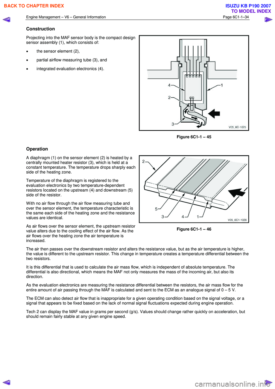
Projecting into the MAF sensor body is the compact design
sensor assembly (1), which consists of:
• the sensor element (2),
• partial airflow measuring tube (3), and
• integrated evaluation electronics (4).
Figure 6C1-1 – 45
Operation
A diaphragm (1) on the sensor element (2) is heated by a
centrally mounted heater resistor (3), which is held at a
constant temperature. The temperature drops sharply each
side of the heating zone.
Temperature of the diaphragm is registered to the
evaluation electronics by two temperature-dependent
resistors located on the upstream (4) and downstream (5)
side of the resistor.
W ith no air flow through the air flow measuring tube and
over the sensor element, the temperature characteristic is
the same each side of the heating zone and the resistance
values are identical.
As air flows over the sensor element, the upstream resistor
value alters due to the cooling effect of the air flow. As the
air flows over the heating zone the air temperature is
increased.
Figure 6C1-1 – 46
The air then passes over the downstream resistor and alters the resistance value, but as the air temperature is higher,
the value is different to the upstream resistor. This change in temperature creates a temperature differential between the
two resistors.
It is this differential that is used to calculate the air mass flow, which is independent of absolute temperature. The
differential is also directional, which means the MAF not only measures the mass of the incoming air, but also its
direction.
As the evaluation electronics are measuring the resistance differential between the resistors, the air mass flow for the
entire amount of air passing through the MAF is calculated and sent to the ECM as an analogue signal of 0 – 5 V.
The ECM can also detect air flow that is inappropriate for a given operating condition based on the signal voltage, or a
signal that appears to be fixed based on the lack of normal signal fluctuations expected during engine operation.
Tech 2 can display the MAF value in grams per second (g/s). Values should change rather quickly on acceleration, but
should remain fairly stable at any given engine speed.
BACK TO CHAPTER INDEX
TO MODEL INDEX
ISUZU KB P190 2007
Page 3279 of 6020
Engine Management – V6 – Diagnostics Page 6C1-2–1
6C1-2 Engine Management – V6
Diagnostics
ATTENTION
Before performing any service operation or other procedure described in this Section, refer to 1.5 Warning
Caution and Notes for correct workshop practices with regard to safety and/or property damage.
1 General Information ............................................................................................................ ...................4
1.1 Diagnostic System Check ..................................................................................................................................... 4
1.2 Diagnostic Trouble Code Tables ................................................................................................. ......................... 4
1.3 Symptoms Diagnostics ......................................................................................................................................... 5
1.4 Diagnostic Trouble Codes .................................................................................................................................... 5
1.5 Warning Caution and Notes .................................................................................................................................. 6
2 GM LAN Serial Communication Circuit ............................................................................................ ....8
3 Wiring Diagrams and Connector Charts ........................................................................................... ...9
3.1 Wiring Diagrams .................................................................................................................................................... 9
3.2 ECM Connector End Views ................................................................................................................................. 12
3.2 Engine Control Connector End Views ............................................................................................. .................. 16
4 Diagnostics Starting Point...................................................................................................................18
4.1 Basic Requirements ............................................................................................................................................ 18
4.2 Diagnostic Precautions ......................................................................................................... .............................. 18
4.3 Preliminary Checks.............................................................................................................................................. 19
4.4 Diagnostic System Check ........................................................................................................ ........................... 20
5 Symptoms Diagnostics ........................................................................................................................22
5.1 Symptoms Diagnosis Table ....................................................................................................... ......................... 22
5.2 Intermittent Fault Conditions .............................................................................................................................. 22
5.3 Backfire................................................................................................................................................................. 24
5.4 Cranks But Does Not Run ........................................................................................................ ........................... 26
5.5 Cuts Out, Misses.................................................................................................................................................. 27
5.6 Detonation / Spark Knock ....................................................................................................... ............................ 28
5.7 Dieseling, Run-on ................................................................................................................................................ 28
5.8 Hard Start ............................................................................................................................................................. 29
5.9 Hesitation, Sag and Stumble .................................................................................................... .......................... 30
5.10 Lack of Power, Sluggishness or Sponginess ...................................................................................... ............. 31
5.11 Poor Fuel Economy ............................................................................................................................................. 32
5.12 Rough, Unstable, Incorrect Idle or Stalling .................................................................................... ................... 34
5.13 Surges / Chuggles ............................................................................................................................................... 35
6 Functional Checks................................................................................................................................37
6.1 General Information ............................................................................................................ ................................. 37
6.2 Fuel Injector Coil Test ......................................................................................................................................... 37
6.3 Fuel Injector Balance Test ..................................................................................................... ............................. 42
6.4 Fuel Injector Leak Down Test ................................................................................................... .......................... 44
6.5 Alcohol / Contaminants in Fuel Diagnosis ....................................................................................... ................. 46
6.6 Crankshaft Position (CKP) System Variation Learn Procedure..................................................................... .. 46
6.7 Throttle Body Relearn.......................................................................................................................................... 47
BACK TO CHAPTER INDEX
TO MODEL INDEX
ISUZU KB P190 2007
Page 3282 of 6020
Engine Management – V6 – Diagnostics Page 6C1-2–4
1 General Information
1.1 Diagnostic System Check
The engine management diagnostic procedure is organised in a logical structure that begins with the Diagnostic System
Check. The Diagnostic System Check directs the diagnostic procedure to the logical steps necessary to diagnose an
engine driveability fault condition.
1.2 Diagnostic Trouble Code Tables
The Diagnostic System Check directs the diagnostic procedure to the appropriate diagnostic trouble code (DTC) tables
if there is a DTC currently stored in the engine control module (ECM).
The diagnostic tables locate a faulty circuit or component through a logic based on the process of elimination. These
diagnostic tables are developed with the following assumptions:
• the vehicle functioned correctly at the time of assembly,
• there are no multiple faults, and
• the problem currently exists.
Understanding and the correct use of the diagnostic tables are essential to reduce diagnostic time and to prevent
misdiagnosis.
Multiple DTC Fault Conditions
Some fault conditions trigger multiple component DTCs even if the fault condition exists only on a single component. If
there are multiple DTCs stored in the ECM, the service technician must view and record all DTCs logged.
The relationship between the logged DTCs can then be analysed to determine the source of the fault condition. Always
begin the diagnostic process with the DTC table of the fault condition that may trigger other DTCs to set.
The following fault conditions may trigger multiple DTCs:
• a fault in the serial data communication circuit,
• a system voltage that is too low may cause incorrect engine management system operation or engine
management component malfunction,
• a system voltage that is too high may damage the ECM and/or other engine management components,
• fault condition in the ECM read only memory (ROM) or random access memory (RAM),
• fault condition in the ECM internal circuitry or programming,
• improperly connected sensor or component wiring connector, or
• an electrical fault condition in the following shared ECM electrical circuits trigger DTCs on components or sensors
that share in the faulty shared circuit. Test the electrical circuit of the appropriate sensors or components to isolate
the fault condition. Refer to 3 W iring Diagrams and Connector Charts in this Section.
• 5 V Reference Circuit,
• Low Reference Circuit, or
• Ignition Control Voltage Circuit.
If there are no obvious faults to begin a multiple DTC fault condition diagnostic procedure, diagnose the DTCs in the
following order unless directed otherwise:
1 Always start with the lowest numbered component level DTCs such as:
• sensor DTCs,
• solenoid DTCs, or
• relay DTCs.
2 Then follow with system level DTCs such as:
• misfire DTCs,
BACK TO CHAPTER INDEX
TO MODEL INDEX
ISUZU KB P190 2007
Page 3283 of 6020
Engine Management – V6 – Diagnostics Page 6C1-2–5
• fuel trim DTCs, or
• catalyst DTCs.
1.3 Symptoms Diagnostics
The Diagnostic System Check directs the service technician to the symptoms diagnostics if the following conditions
exist:
• a vehicle driveability fault condition exists,
• there is no current diagnostic trouble code presently stored in the ECM, and
• all Tech 2 engine data parameters are within normal operating range.
1.4 Diagnostic Trouble Codes
The ECM constantly performs self-diagnostic tests on the engine management system. W hen the ECM detects a fault
condition in the engine operating parameters, the ECM sets a diagnostic trouble code (DTC) to represent that fault
condition. The following are the types of DTCs programmed in the ECM. In addition, DTCs are classified as either a
current or history DTC.
• Type A – emission related DTCs,
• Type B – emission related DTCs, and
• Type C – non-emission related DTCs.
NOTE
Depending on the type of DTC set, the ECM may
command the malfunction indicator lamp (MIL) to
illuminate and warn the driver there is a fault in
the engine management system.
Type A – Emission Related DTCs
The ECM takes the following action when a Type A DTC runs and fails:
• sets a current Type A DTC that represents the fault condition,
• illuminates the instrument cluster malfunction indicator lamp (MIL), and
• records the operating condition at the time the diagnostic fails and stores this information in the freeze frame
failure record.
Type B – Emission Related DTCs
The ECM takes the following action when a Type B DTC runs and fails:
• On the first time a Type B DTC fails, the ECM takes the following actions:
− sets a current Type B DTC that represents the fault condition, and
− records the operating conditions at the time the fault sets and stores this information in the failure records.
• On the second consecutive ignition cycle that a Type B DTC fails, the ECM takes the following actions:
− activates the instrument cluster malfunction indicator lamp (MIL), and
− records the operating condition at the time the diagnostic fails and stores this information in the freeze frame
failure record.
Conditions for Clearing Type A or Type B DTCs
• The current DTC clears when there is no fault condition in the current ECM self-diagnostics.
• If there are no DTCs logged after three or four consecutive ignition cycles, the ECM deactivates the instrument
cluster malfunction indicator lamp (MIL).
• Type A or Type B History DTC clears when there is no fault condition after 40 consecutive warm-up cycles.
BACK TO CHAPTER INDEX
TO MODEL INDEX
ISUZU KB P190 2007
Page 3284 of 6020
Engine Management – V6 – Diagnostics Page 6C1-2–6
• Use Tech 2 to clear DTC/s.
Type C – Non-Emission Related DTCs
The ECM takes the following action when a Type A DTC runs and fails:
• sets a current Type C DTC that represents the fault condition, and
• records the operating conditions at the time the DTC is logged and stores this information in the Failure Record,
and:
NOTE
The instrument cluster malfunction indicator lamp
(MIL) is not activated when a Type C DTC sets.
Conditions for Clearing Type C DTCs
• The current DTC clears when there is no fault condition in the current ECM self-diagnostics.
• Type C History DTC clears when there is no fault condition after 40 consecutive warm-up cycles.
• Use Tech 2 to clear DTCs.
Current DTCs
A DTC is a Current DTC if the fault condition that triggers that DTC is present during the last ECM self-diagnostics.
History DTCs
A DTC is a History DTC if the fault condition that triggers that DTC is not present during the last ECM self-diagnostics.
1.5 Warning Caution and Notes
This Section contains various W ARNINGS, CAUTIONS and NOTE statements that you must observe carefully to reduce
the risk of death or injury during service, repair procedures or vehicle operation. Incorrect service or repair procedures
may damage the vehicle or cause operational faults. W ARNINGS, CAUTION and NOTE statements are not exhaustive.
GM Holden LTD can not possibly warn of all the potentially hazardous consequences of failure to follow these
instructions.
Definition of WARNING, CAUTION and NOTE Statements
Diagnosis and repair procedures in this Section contain both general and specific W ARNING, CAUTION and NOTE
statements. GM Holden LTD is dedicated to the presentation of service information that helps the technician to diagnose
and repair the systems necessary for proper operation of the vehicle. Certain procedures may present a hazard to the
technician if they are not followed in the recommended manner. W ARNING, CAUTION and NOTE statements are
designed to help prevent these hazards from occurring, but not all hazards can be foreseen.
WARNING defined
A W ARNING statement immediately precedes an operating procedure or maintenance practice which, if not correctly
followed, could result in death or injury. A W ARNING statement alerts you to take necessary action or not to take a
prohibited action. If a W ARNING statement is ignored, the following consequences may occur:
• Death or injury to the technician or other personnel working on the vehicle,
• Death or injury to other people in or near the workplace area, and / or
• Death or injury to the driver / or passenger(s) of the vehicle or other people, if the vehicle has been improperly
repaired.
CAUTION defined
A CAUTION statement immediately precedes an operating procedure or maintenance practice which, if not correctly
followed, could result in damage to or destruction of equipment, or corruption of data. If a CAUTION statement is
ignored, the following consequences may occur:
BACK TO CHAPTER INDEX
TO MODEL INDEX
ISUZU KB P190 2007
Page 3285 of 6020
Engine Management – V6 – Diagnostics Page 6C1-2–7
• Damage to the vehicle,
• Unnecessary vehicle repairs or component replacement,
• Faulty operation or performance of any system or component being repaired,
• Damage to any system or components which depend on the proper operation of the system or component being
repaired,
• Faulty operation or performance of any systems or components which depend on the proper operation or
performance of the system or component under repair,
• Damage to fasteners, basic tools or special tools and / or
• Leakage of coolant, lubricant or other vital fluids.
NOTE defined
A NOTE statement immediately precedes or follows an operating procedure, maintenance practice or condition that
requires highlighting. A NOTE statement also emphasises necessary characteristics of a diagnostic or repair procedure.
A NOTE statement is designed to:
• Clarify a procedure,
• Present additional information for accomplishing a procedure,
• Give insight into the reasons for performing a procedure in the recommended manner, and / or
• Present information that gives the technician the benefit of past experience in accomplishing a procedure with
greater ease.
BACK TO CHAPTER INDEX
TO MODEL INDEX
ISUZU KB P190 2007