2007 ISUZU KB P190 ECO mode
[x] Cancel search: ECO modePage 3181 of 6020

Engine Cooling – V6 Engine Page 6B1–46
6 Remove the two coolant outlet housing attaching
bolts (1), and remove coolant outlet housing (2).
7 Remove and discard coolant outlet housing O-ring (3) and seal (4).
Figure 6B1 – 51
Reinstall
1 Ensure that the coolant outlet housing and front outlet mating surfaces are clean and dry.
2 Install new O-ring and seal to coolant outlet housing.
3 Install coolant outlet housing and attaching bolts. Tighten all bolts to the correct torque specification.
Coolant outlet housing to front
outlet bolt torque specification..............................10 N.m
Always wear protective safety glasses when
working with spring type hose clamps. Failure
to do so could result in eye injury.
4 Connect the upper radiator hose and clamp to the coolant outlet housing connection.
5 Close the radiator drain tap on the lower RHS of the radiator and remove the piece of rubber tubing to the tap outlet.
6 Reinstall the intake manifold assembly. Refer to 6A1 Engine Mechanical.
7 Refill cooling system. Refer to 3.3 Draining and Filling Cooling System in this Section.
8 Check for coolant leaks. Refer to 3.7 Pressure Testing in this Section.
9 Reconnect battery ground lead. Refer to 8A – Electrical Body & Chassis.
3.12 Coolant Inlet Pipe
Remove
Refer to 3.1 Service Notes in this Section, for
important safety items.
1 Allow engine to cool to ambient temperature (less than 50 ° C), and then remove the coolant filler cap (located at
the front left-hand side of the engine).
BACK TO CHAPTER INDEX
TO MODEL INDEX
ISUZU KB P190 2007
Page 3183 of 6020
Engine Cooling – V6 Engine Page 6B1–48
Install
1 Ensure that the coolant inlet pipe and thermostat housing mating surfaces are clean and dry.
2 Install new O-ring to the coolant inlet pipe.
3 Install coolant inlet pipe at the thermostat housing and secure with the attaching bolt. Tighten all bolts to the correct torque specification.
Coolant inlet pipe to thermostat
housing bolt torque specification ..........................23 N.m
4 Raise the front of the vehicle and support on safety stands. Refer to 0A General Information for the location of jacking and support points.
5 Reinstall the coolant inlet pipe to the engine block and secure with the bolt tightened to the correct torque specification.
Coolant inlet pipe to engine block bolt
torque specification .............................................25 N.m
Always wear protective safety glasses when
working with spring type hose clamps. Failure
to do so could result in eye injury.
6 Connect the lower radiator outlet hose and clamp to the coolant inlet pipe connection.
7 Close the radiator drain tap on the lower RHS of the radiator and remove the piece of rubber tubing to the tap outlet.
8 Lower the front of the vehicle.
9 Refill cooling system. Refer to 3.3 Draining and Filling Cooling System in this Section.
10 Check for coolant leaks. Refer to 3.7 Pressure Testing in this Section.
11 Reconnect battery ground lead. Refer to 8A – Electrical Body & Chassis.
3.13 Cooling Fan and Shroud Assembly
Remove
Disconnection of the battery affects certain
vehicle electronic systems. Refer to 1.1
WARNING, CAUTION and NOTES, before
removing the ground lead.
1 Disconnect the battery ground lead. Refer to 8A – Electrical Body & Chassis.
2 Remove the intake duct and mass air flow as an assembly. Refer to 6A1 Engine Mechanical.
3 Remove the coolant recovery hose from the fan shroud retaining clip.
BACK TO CHAPTER INDEX
TO MODEL INDEX
ISUZU KB P190 2007
Page 3191 of 6020
Engine Cooling – V6 Engine Page 6B1–56
Reinstall
Installation of the radiator is the reverse of removal procedures, noting the following points:
1 Before installing radiator, inspect core to ensure that there is no foreign matter in core fins. Clean out between core fins with compressed air, blowing from rear to front.
2 If the vehicle is fitted with an automatic transmission, remove plugs from the removed cooling pipe ends and the two quick connect fittings.
3 After wiping cooler line ends and smearing clean automatic transmission fluid over each flared line end, push into the quick connect fitting to engage. As a security check, tug on each line to ensure correct engagement.
4 Check the transmission fluid level. Refer to the following references as required:
• 7C4 Automatic Transmission
• 4L60E On-vehicle Servicing
5 Install the following hoses:
a. Lower radiator hose, securing with the hose clamp.
b. Upper radiator hose, securing with the hose clamp.
6 Install the radiator cooling fan and shroud assembly. Refer to 3.13Cooling Fan and Shroud Assembly in this Section. Ensure that electrical connectors and the transmission cooler lines are seated correctly in the integral
retainer clips before install upper radiator shroud.
7 Refill cooling system. Refer to 3.3 Draining and Filling Cooling System in this Section.
8 Check for coolant leaks. Refer to 3.7 Pressure Testing in this Section.
9 Reconnect battery ground lead. Refer to 8A Electrical Body & Chassis.
10 Check cooling fan operation. Refer to 6C1-2 Engine Management Diagnostics. Also check for correct rotational direction of cooling fan.
BACK TO CHAPTER INDEX
TO MODEL INDEX
ISUZU KB P190 2007
Page 3192 of 6020
Engine Cooling – V6 Engine Page 6B1–57
Radiator Repair Procedure
Repairable Leaks
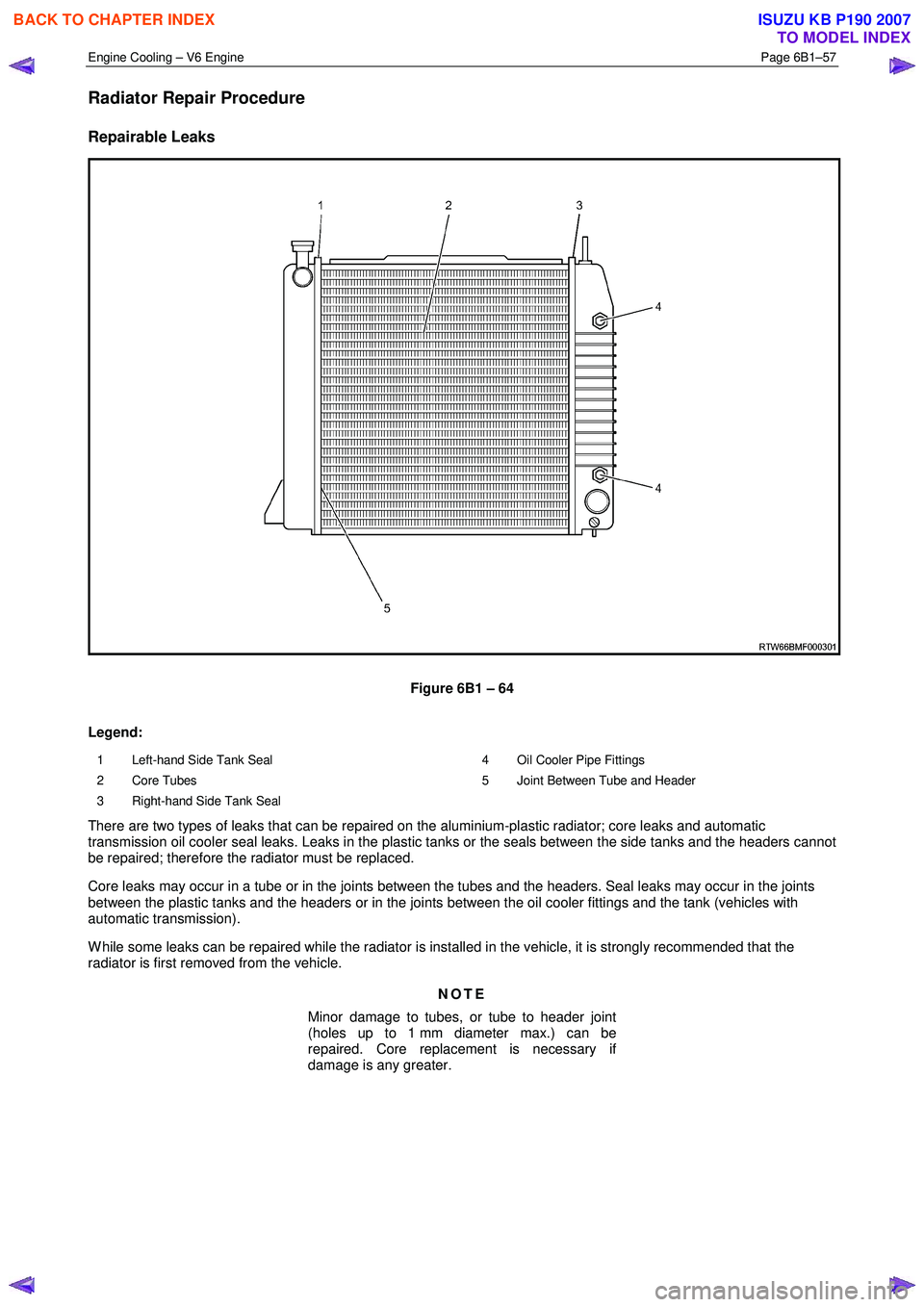
Figure 6B1 – 64
Legend:
1 Left-hand Side Tank Seal
2 Core Tubes
3 Right-hand Side Tank Seal 4 Oil Cooler Pipe Fittings
5 Joint Between Tube and Header
There are two types of leaks that can be repaired on the aluminium-plastic radiator; core leaks and automatic
transmission oil cooler seal leaks. Leaks in the plastic tanks or the seals between the side tanks and the headers cannot
be repaired; therefore the radiator must be replaced.
Core leaks may occur in a tube or in the joints between the tubes and the headers. Seal leaks may occur in the joints
between the plastic tanks and the headers or in the joints between the oil cooler fittings and the tank (vehicles with
automatic transmission).
W hile some leaks can be repaired while the radiator is installed in the vehicle, it is strongly recommended that the
radiator is first removed from the vehicle.
NOTE
Minor damage to tubes, or tube to header joint
(holes up to 1 mm diameter max.) can be
repaired. Core replacement is necessary if
damage is any greater.
BACK TO CHAPTER INDEX
TO MODEL INDEX
ISUZU KB P190 2007
Page 3193 of 6020
Engine Cooling – V6 Engine Page 6B1–58
Repair Method
Repairs to the aluminium radiator core should only be made using the recommended 'Aluminised Silicon' based liquid
repair agent, in accordance with the recommended procedure outlined in General Core Repair in this Section. Refer to
the current Partfinder™ for Aluminised Silicon base liquid part number.
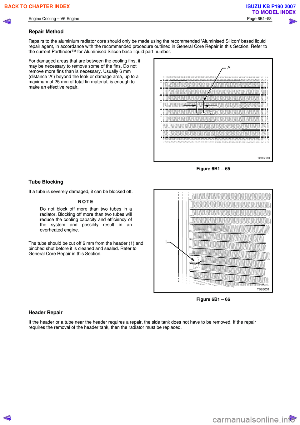
For damaged areas that are between the cooling fins, it
may be necessary to remove some of the fins. Do not
remove more fins than is necessary. Usually 6 mm
(distance ‘A’) beyond the leak or damage area, up to a
maximum of 25 mm of total fin material, is enough to
make an effective repair.
Figure 6B1 – 65
Tube Blocking
If a tube is severely damaged, it can be blocked off.
NOTE
Do not block off more than two tubes in a
radiator. Blocking off more than two tubes will
reduce the cooling capacity and efficiency of
the system and possibly result in an
overheated engine.
The tube should be cut off 6 mm from the header (1) and
pinched shut before it is cleaned and sealed. Refer to
General Core Repair in this Section.
Figure 6B1 – 66
Header Repair
If the header or a tube near the header requires a repair, the side tank does not have to be removed. If the repair
requires the removal of the header tank, then the radiator must be replaced.
BACK TO CHAPTER INDEX
TO MODEL INDEX
ISUZU KB P190 2007
Page 3195 of 6020
Engine Cooling – V6 Engine Page 6B1–60
Transmission Oil Cooler Leak Test
If the transmission oil cooler is suspected of leaking oil, test it before the radiator is replaced, as follows:
1 Disconnect oil cooler pipes at the flexible hose connections. Refer to 3.14 Flexible Transmission Cooler Hose, in this Section.
2 Plug one of the connections, using a blocked pipe fitting and attach an air supply to the other flexible hose.
3 Remove coolant filler cap and check that the coolant is filled to the coolant filler cap filler neck.
4 Apply air pressure gradually, increasing up to an absolute maximum of 110 kPa. If bubbles appear in radiator neck, the oil cooler is leaking and the radiator assembly must be replaced.
Transmission Oil Cooler Seal Replacement.
It is strongly recommended that the transmission oil cooler connector fittings to the right-hand side radiator header tank,
not be disturbed. If coolant is found to leak from either of these two areas, then the radiator should be replaced.
BACK TO CHAPTER INDEX
TO MODEL INDEX
ISUZU KB P190 2007
Page 3196 of 6020
Engine Cooling – V6 Engine Page 6B1–61
4 Engine Cooling System
Diagnosis
4.1 Poor Heater Operation
Little or no heat coming from the heater, especially at idle could be an indication of a cooling system problem.
As the coolant level begins to get lower than normal, air enters the system to replace the missing coolant. The heater
core is one of the highest parts of the cooling system and therefore, the first area to lose coolant circulation.
At first, with a small amount of coolant loss, lack of heat will be most noticeable at idle. As driving speed increases, the
engine pumps more coolant and more heat is now able to pass through the heater core.
If coolant level drops even lower, heater operation will become less effective, even during normal driving. Cooling and
engine systems can be adversely affected if problem is not corrected before overheating occurs.
4.2 Leaking Cylinder Head Gasket
Combustion gases leaking past the cylinder head gasket can pressurise the cooling system, forcing coolant out of the
system and into the coolant recovery reservoir.
Indications are air bubbles in the coolant or an overflow condition of the recovery reservoir.
4.3 Question the Customer
To avoid needless time and cost in diagnosing cooling system complaints, the customer should be questioned about
driving conditions that place abnormal loads on the cooling system.
1 Is overheating occurring after prolonged idle, in gear, with air conditioning system operating?
If answer is YES – instruct owner on driving techniques that would avoid overheating such as:
• Idle in neutral as much as possible – increase engine rpm to get higher air flow (due to an increase in voltage
to the fan) and coolant flow through the radiator
• Turn air conditioning system off during extended idling periods if overheating is indicated on temperature
gauge. Further diagnostic checks should not be required
2 Is overheating occurring after prolonged driving in slow city traffic, traffic jams, parades, etc?
If answer is YES, explain driving technique to the customer, that would avoid overheating – same as for prolonged idle – No.1. Further diagnostic checks should not be required.
4.4 Diagnostic Chart
If none of the above conditions apply, refer to the following Diagnosis Chart.
To effectively use this chart, question the customer to determine which of the following three categories apply to the
complaint:
1 If complaint is hot indication on temperature gauge.
W as temperature reading accompanied by boiling?
• If answer is YES, go to overheating on diagnosis chart
• If answer is NO, check temperature gauge and sender
2 If complaint is boiling – go to overheating on diagnosis chart.
3 If complaint is coolant loss. Determine if customer is filling the system correctly.
4 If incorrect filling is not the problem, go to coolant loss in the diagnosis chart.
BACK TO CHAPTER INDEX
TO MODEL INDEX
ISUZU KB P190 2007
Page 3198 of 6020
Engine Cooling – V6 Engine Page 6B1–63
4.5 Problems Not Requiring Disassembly of
Cooling System
1 Large obstructions blocking radiator or condenser airflow.
• Auxiliary oil coolers
• License plate
• Obstruction of radiator grille, for example, driving lights or mud
2 Loose, damaged or missing air chute side panels.
3 Missing or damaged air baffle.
4 Cracked or loose coolant recovery system hose.
5 Leaking heater component such as the heater core or water valve.
4.6 Problems Requiring Disassembly of Cooling System
1 Damaged cooling fan or faulty motor operation.
2 Pressure test cooling system.
3 Defective coolant pump.
• Eroded or broken impeller vanes
• Failed bearing or seal – check for shaft or bearing end play
4 Internally blocked radiator core.
5 Obstruction of coolant recovery system.
6 Internal system leaks.
• Head gaskets
• Cracked cylinder block
• Engine front cover
• Intake manifold gaskets
7 Blocked coolant passages in cylinder heads or block – remove cylinder heads and check.
4.7 Black Light and Dye Leak Diagnosis Method
It is strongly recommended that this diagnostic method be used to diagnose fluid leaks. This method is a proven and
reliable method that identifies the specific leak source.
The black light kit can be used for the leak detection of a number of fluids, when used with the appropriate tracer dye.
Examples are: Coolant, Engine Oil, Automatic Transmission Fluid and Air Conditioning Refrigerant (R134A).
The following is a summary of the steps involved in detecting a cooling system fluid leak using black light and dye:
1 Pour specified amount of dye into the cooling system via the coolant filler cap on the outlet housing. Refer 3.1 Service Notes in this Section.
2 Road test the vehicle under normal operating conditions.
3 Direct the light towards the suspect area. The fluid leak will appear as a brightly coloured path leading from the source.
4 Repair fluid leak and recheck to ensure that leak has been rectified.
5 Refer to the manufacturer’s directions when using this method.
BACK TO CHAPTER INDEX
TO MODEL INDEX
ISUZU KB P190 2007