Page 3158 of 6020

Engine Cooling – V6 Engine Page 6B1–23
1 W ith the engine off, remove the coolant filler cap on
the coolant outlet housing, located at the front left-
hand side of the engine.
Figure 6B1 – 19
2 If filling a completely empty cooling system for automatic transmission models, mix 5 litres of clean
water with 5 litres of the recommended coolant or
5.2 litres of each for manual transmission models.
3 Add coolant via the engine coolant filler neck on the coolant outlet housing.
NOTE
Do not replace the coolant filler cap before
starting the engine (in step 6). Leaving the filler
cap off allows the engine to warm up without
pressurising.
4 Reconnect battery ground lead. Refer to 6D1 – 3 Battery – V6.
5 Start the engine and set the HVAC controls to: • Full hot
• Low fan
Figure 6B1 – 20
6 Run the engine at approximately 2,000 rpm to warm up the engine.
7 W ait until the radiator fan switches on.
8 W hen the radiator fan has switched on, let the engine rpm drop back to idle.
9 Turn the engine off when the radiator fan switches off.
10 Top up the coolant until full.
11 Replace the coolant filler cap.
Do not loosen or remove the radiator filler cap
when the coolant temperature is high. Steam
or boiling coolant will gush out and you may
be burnt. To open the radiator filler cap, cover
the filler cap with a thick cloth when the
coolant has cooled, release the pressure by
slowly turning the filler cap, and remove the
cap.
BACK TO CHAPTER INDEX
TO MODEL INDEX
ISUZU KB P190 2007
Page 3159 of 6020
Engine Cooling – V6 Engine Page 6B1–24
12 Open the coolant reservoir tank cap.
13 Top up the radiator coolant recovery reservoir to the MAX line.
14 Reinstall the coolant recovery reservoir cap.
NOTE
This condition only applies when the cooling
system is first being filled after a major loss of
coolant. The level of coolant in the reservoir
will then drop, once the engine is started and
normal operating temperature is reached. The
coolant level should then be maintained at the
correct level (between the MAX and MIN
Lines).
Figure 6B1 – 21
BACK TO CHAPTER INDEX
TO MODEL INDEX
ISUZU KB P190 2007
Page 3160 of 6020
Engine Cooling – V6 Engine Page 6B1–25
3.4 Cleaning Cooling System
NOTE
• Before carrying out reverse flushing
procedures, it is recommended that a
cleaning solution be used to loosen scale and
corrosion. Only use a Holden approved
radiator cleaner following the instructions on
the container label.
• This operation should only be carried out
when the engine and radiator are at ambient
temperature.
• When using specialised cooling system
flushing equipment, connect the equipment as
recommended by the manufacturer.
Cooling System Reverse Flush
Radiator
Refer to ‘
‘‘
‘
Environmental Issues ’
’’
’
in 3.1
Service Notes, before draining the coolant.
1 Drain the cooling system. Refer to 3.3 Draining and Filling Cooling System in this Section.
Always wear eye protection when working
with spring-type hose clamps. Failure to do
so may result in eye injury.
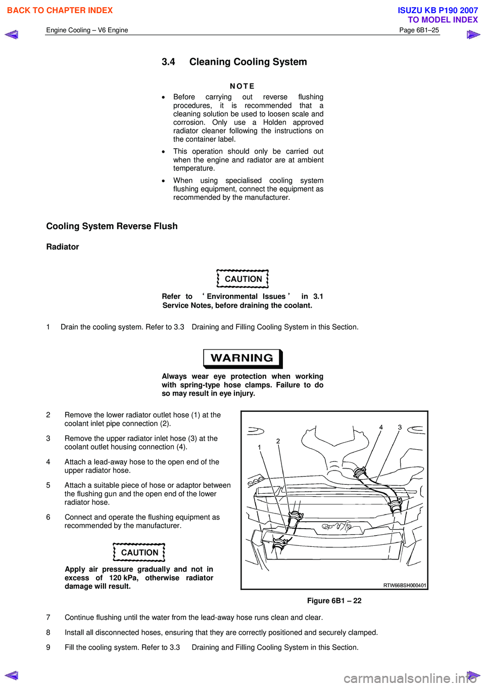
2 Remove the lower radiator outlet hose (1) at the coolant inlet pipe connection (2).
3 Remove the upper radiator inlet hose (3) at the coolant outlet housing connection (4).
4 Attach a lead-away hose to the open end of the upper radiator hose.
5 Attach a suitable piece of hose or adaptor between the flushing gun and the open end of the lower
radiator hose.
6 Connect and operate the flushing equipment as recommended by the manufacturer.
Apply air pressure gradually and not in
excess of 120 kPa, otherwise radiator
damage will result.
Figure 6B1 – 22
7 Continue flushing until the water from the lead-away hose runs clean and clear.
8 Install all disconnected hoses, ensuring that they are correctly positioned and securely clamped.
9 Fill the cooling system. Refer to 3.3 Draining and Filling Cooling System in this Section.
BACK TO CHAPTER INDEX
TO MODEL INDEX
ISUZU KB P190 2007
Page 3161 of 6020
Engine Cooling – V6 Engine Page 6B1–26
10 Pressure test the cooling system. Refer to 3.7 Pressure Testing in this Section.
Engine
Refer to ‘
‘‘
‘
Environmental Issues ’
’’
’
in 3.1
Service Notes, before draining the coolant.
1 Drain the cooling system. Refer to 3.3 Draining and Filling Cooling System in this Section.
Always wear eye protection when working
with spring-type hose clamps. Failure to do
so may result in eye injury.
2 Remove the upper and lower radiator hoses from the coolant outlet housing and coolant inlet pipe connections. Refer to Figure 6B1 – 22.
3 Remove the thermostat housing from the rear of the engine block. Refer to 6A1 Engine Mechanical – V6..
4 Remove the thermostat from the thermostat housing and reinstall the housing to the rear of the intake manifold. Refer to 3.8 Thermostat in this Section.
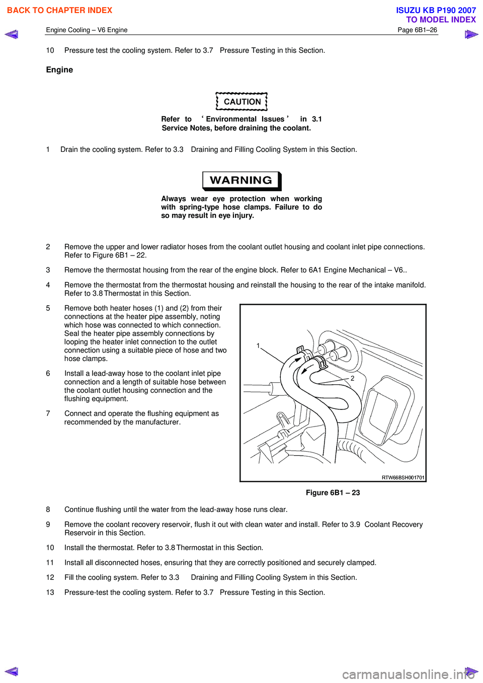
5 Remove both heater hoses (1) and (2) from their connections at the heater pipe assembly, noting
which hose was connected to which connection.
Seal the heater pipe assembly connections by
looping the heater inlet connection to the outlet
connection using a suitable piece of hose and two
hose clamps.
6 Install a lead-away hose to the coolant inlet pipe connection and a length of suitable hose between
the coolant outlet housing connection and the
flushing equipment.
7 Connect and operate the flushing equipment as recommended by the manufacturer.
Figure 6B1 – 23
8 Continue flushing until the water from the lead-away hose runs clear.
9 Remove the coolant recovery reservoir, flush it out with clean water and install. Refer to 3.9 Coolant Recovery Reservoir in this Section.
10 Install the thermostat. Refer to 3.8 Thermostat in this Section.
11 Install all disconnected hoses, ensuring that they are correctly positioned and securely clamped.
12 Fill the cooling system. Refer to 3.3 Draining and Filling Cooling System in this Section.
13 Pressure-test the cooling system. Refer to 3.7 Pressure Testing in this Section.
BACK TO CHAPTER INDEX
TO MODEL INDEX
ISUZU KB P190 2007
Page 3162 of 6020
Engine Cooling – V6 Engine Page 6B1–27
Heater Hoses and Core
Refer to ‘
‘‘
‘
Environmental Issues ’
’’
’
in 3.1
Service Notes, before draining the coolant.
1 Drain the cooling system. Refer to 3.3 Draining and Filling Cooling System in this Section.
Always wear eye protection when working
with spring-type hose clamps. Failure to do
so may result in eye injury.
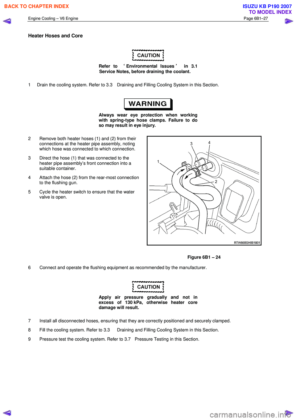
2 Remove both heater hoses (1) and (2) from their connections at the heater pipe assembly, noting
which hose was connected to which connection.
3 Direct the hose (1) that was connected to the heater pipe assembly’s front connection into a
suitable container.
4 Attach the hose (2) from the rear-most connection to the flushing gun.
5 Cycle the heater switch to ensure that the water valve is open.
Figure 6B1 – 24
6 Connect and operate the flushing equipment as recommended by the manufacturer.
Apply air pressure gradually and not in
excess of 130 kPa, otherwise heater core
damage will result.
7 Install all disconnected hoses, ensuring that they are correctly positioned and securely clamped.
8 Fill the cooling system. Refer to 3.3 Draining and Filling Cooling System in this Section.
9 Pressure test the cooling system. Refer to 3.7 Pressure Testing in this Section.
BACK TO CHAPTER INDEX
TO MODEL INDEX
ISUZU KB P190 2007
Page 3174 of 6020
Engine Cooling – V6 Engine Page 6B1–39
18 Check for coolant leaks. Refer to 3.7 Pressure Testing in this Section.
19 Install the radiator shroud.
20 Install the engine dress covers. Refer to 6A1 Engine Mechanical.
21 Reconnect battery ground lead. Refer to 8A_ Electrical Body & Chassis.
22 Road test the vehicle to check for correct operation.
3.9 Coolant Recovery Reservoir
Remove
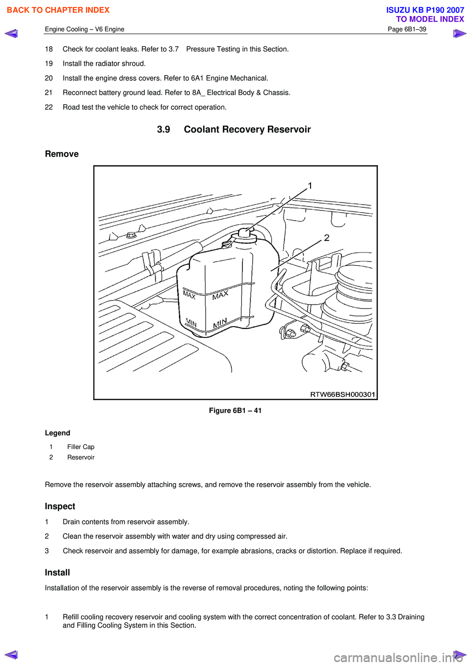
Figure 6B1 – 41
Legend
1 Filler Cap
2 Reservoir
Remove the reservoir assembly attaching screws, and remove the reservoir assembly from the vehicle.
Inspect
1 Drain contents from reservoir assembly.
2 Clean the reservoir assembly with water and dry using compressed air.
3 Check reservoir and assembly for damage, for example abrasions, cracks or distortion. Replace if required.
Install
Installation of the reservoir assembly is the reverse of removal procedures, noting the following points:
1 Refill cooling recovery reservoir and cooling system with the correct concentration of coolant. Refer to 3.3 Draining and Filling Cooling System in this Section.
BACK TO CHAPTER INDEX
TO MODEL INDEX
ISUZU KB P190 2007
Page 3175 of 6020
Engine Cooling – V6 Engine Page 6B1–40
2 Check coolant recovery system for leaks.
3.10 Coolant Pump
Remove
Refer to 3.1 Service Notes in this Section, for
important safety items.
NOTE
The coolant pump is not to be disassembled and
is replaced only as an assembly.
1 Allow engine to cool to ambient temperature (less than 50 ° C), and then remove the coolant filler cap (located at
the front left-hand side of the engine).
Disconnection of the battery affects certain
vehicle electronic systems. Refer to 1.1
WARNING, CAUTION and NOTES, before
removing the ground lead.
2 Disconnect the battery ground lead. Refer to 8A – Electrical Body & Chassis.
3 Loosen coolant pump pulley to hub bolts (1).
NOTE
While the view shows the drive belt removed,
it will be easier to loosen the four pulley bolts,
with the belt installed.
Figure 6B1 – 42
BACK TO CHAPTER INDEX
TO MODEL INDEX
ISUZU KB P190 2007
Page 3179 of 6020
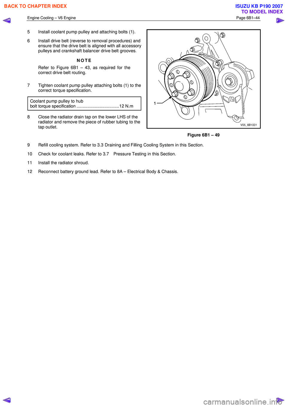
Engine Cooling – V6 Engine Page 6B1–44
5 Install coolant pump pulley and attaching bolts (1).
6 Install drive belt (reverse to removal procedures) and ensure that the drive belt is aligned with all accessory
pulleys and crankshaft balancer drive belt grooves.
NOTE
Refer to Figure 6B1 – 43, as required for the
correct drive belt routing.
7 Tighten coolant pump pulley attaching bolts (1) to the correct torque specification.
Coolant pump pulley to hub
bolt torque specification ...................................12 N.m
8 Close the radiator drain tap on the lower LHS of the radiator and remove the piece of rubber tubing to the
tap outlet.
Figure 6B1 – 49
9 Refill cooling system. Refer to 3.3 Draining and Filling Cooling System in this Section.
10 Check for coolant leaks. Refer to 3.7 Pressure Testing in this Section.
11 Install the radiator shroud.
12 Reconnect battery ground lead. Refer to 8A – Electrical Body & Chassis.
BACK TO CHAPTER INDEX
TO MODEL INDEX
ISUZU KB P190 2007