2007 ISUZU KB P190 ECO mode
[x] Cancel search: ECO modePage 3080 of 6020
Engine Mechanical – V6 Page 6A1–303
Page 6A1–303
4.8 Thread Repairs
General Information
The thread repair process involves a solid, thin walled, self-locking, carbon steel, bushing type insert. During the insert
installation process, the installation dr iver tool cold-rolls the bottom internal threads and expands the bottom external
threads of the insert into the base material. This action mechanically locks the insert into place.
This Section describes the recomm ended method of repairing threads in three specific areas of the engine.
• general thread repair,
• cylinder block main bearing cap bolt hole thread repair, and
• cylinder head bolt hole thread repair.
For detailed descriptions of all th read specifications used refer to 4.9 Thread Repair Specifications .
The drill-bit and counter-bore tool from the thread repair kit, Tool No. J-42385-700 and J-42385-2000 are designed for
use with either a suitable tap wrench or drill motor. Limited access and larger hol e repair may process better using a tap
wrench. An extension from Tool J 43965 may also be required to drive the thread repair tooling dependent on access to
the hole being repaired. Use only a tap wrench when tapping the hole and dur ing installation of the insert.
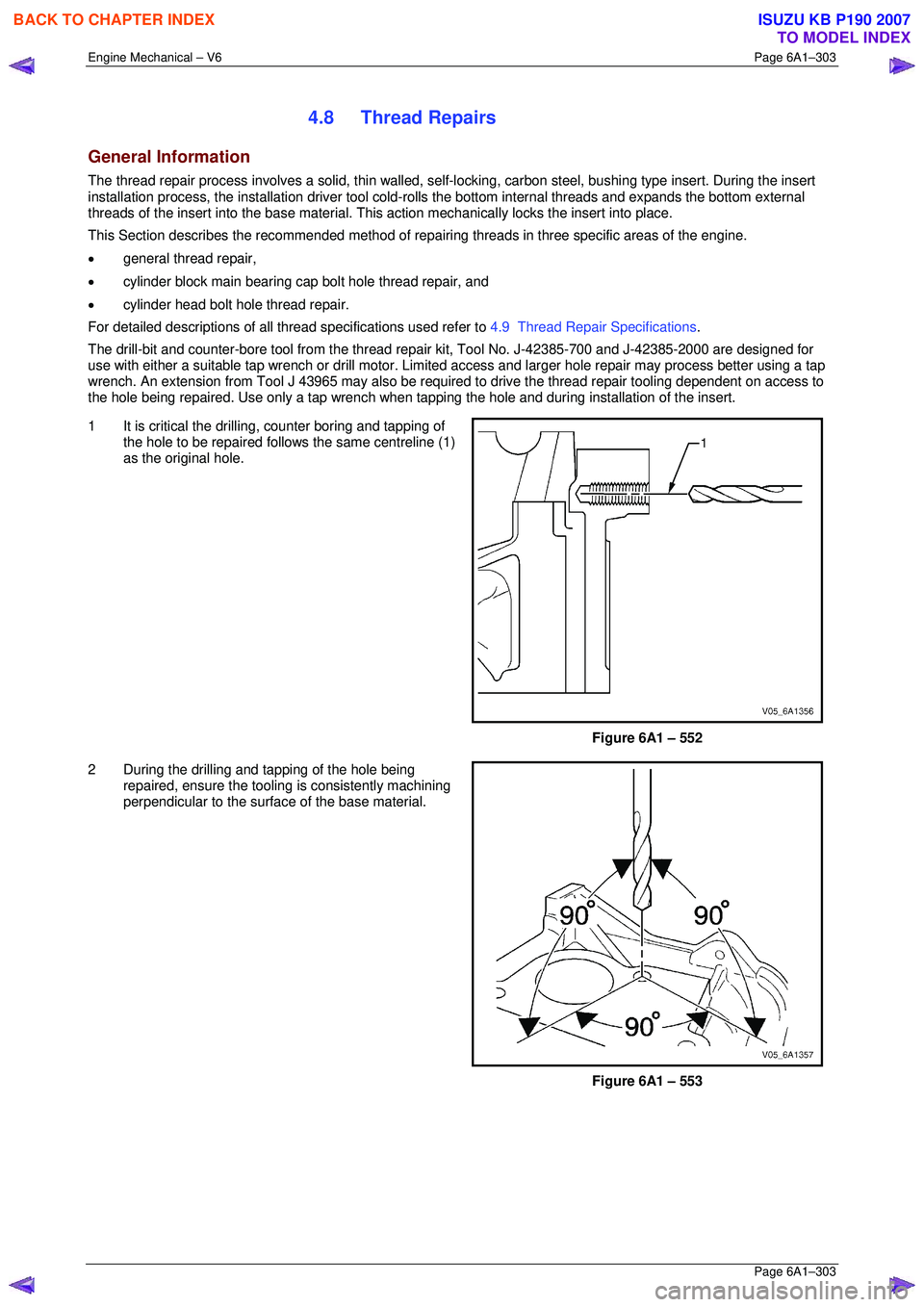
1 It is critical the drilling, counter boring and tapping of
the hole to be repaired follows the same centreline (1)
as the original hole.
Figure 6A1 – 552
2 During the drilling and tapping of the hole being repaired, ensure the tooling is consistently machining
perpendicular to the surface of the base material.
Figure 6A1 – 553
BACK TO CHAPTER INDEX
TO MODEL INDEX
ISUZU KB P190 2007
Page 3081 of 6020
Engine Mechanical – V6 Page 6A1–304
Page 6A1–304
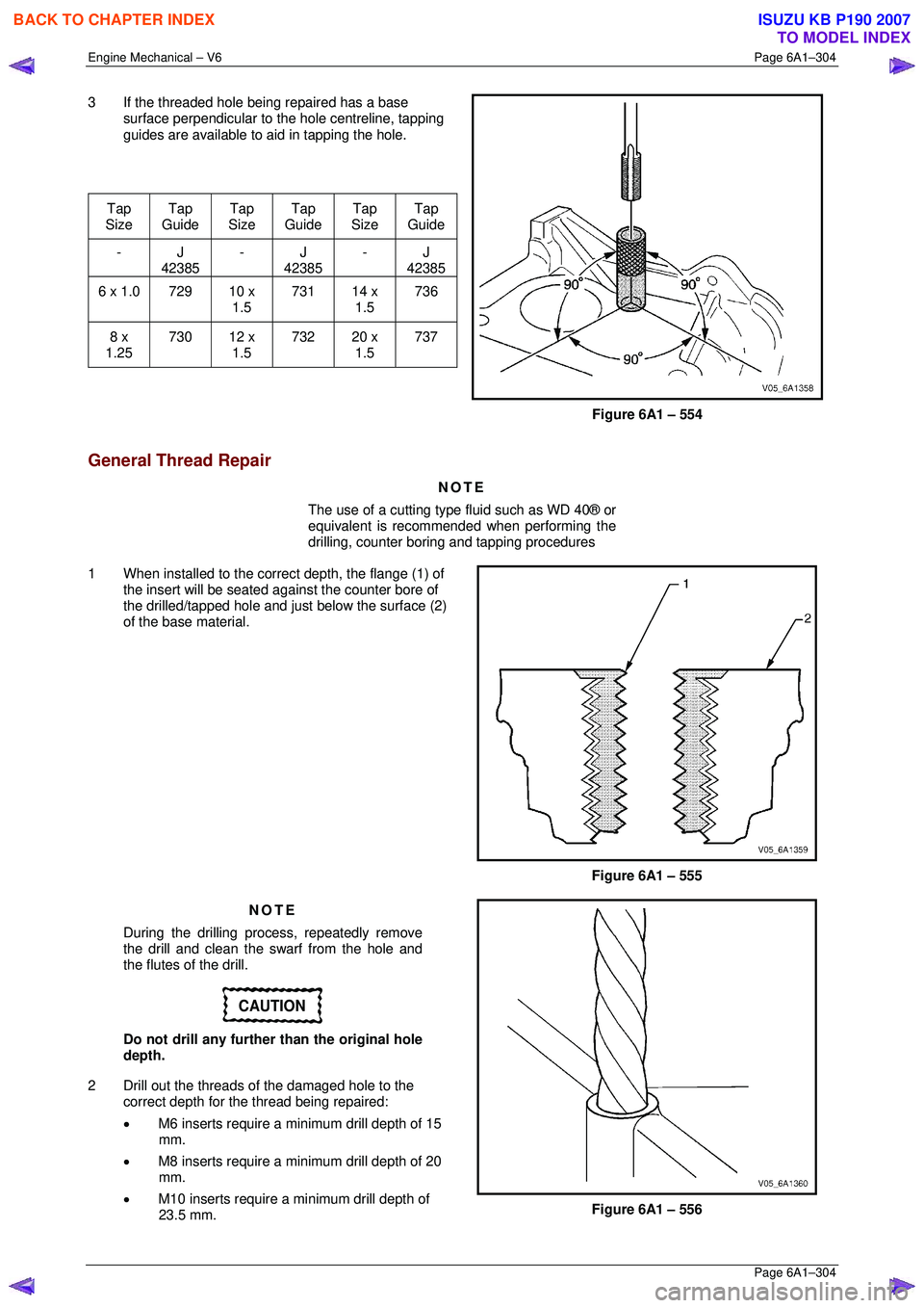
3 If the threaded hole being repaired has a base
surface perpendicular to t he hole centreline, tapping
guides are available to aid in tapping the hole.
Tap
Size Tap
Guide Tap
Size Tap
Guide Tap
Size Tap
Guide
- J 42385 - J
42385 - J
42385
6 x 1.0 729 10 x
1.5 731
14 x
1.5 736
8 x
1.25 730
12 x
1.5 732
20 x
1.5 737
Figure 6A1 – 554
General Thread Repair
NOTE
The use of a cutting type fluid such as WD 40® or
equivalent is recommended when performing the
drilling, counter bori ng and tapping procedures
1 When installed to the corre ct depth, the flange (1) of
the insert will be seated agai nst the counter bore of
the drilled/tapped hole and just below the surface (2)
of the base material.
Figure 6A1 – 555
NOTE
During the drilling process, repeatedly remove
the drill and clean the swarf from the hole and
the flutes of the drill.
CAUTION
Do not drill any further than the original hole
depth.
2 Drill out the threads of the damaged hole to the
correct depth for the thread being repaired:
• M6 inserts require a minimum drill depth of 15
mm.
• M8 inserts require a minimum drill depth of 20
mm.
• M10 inserts require a minimum drill depth of
23.5 mm.
Figure 6A1 – 556
BACK TO CHAPTER INDEX
TO MODEL INDEX
ISUZU KB P190 2007
Page 3087 of 6020
Engine Mechanical – V6 Page 6A1–310
Page 6A1–310
Main Bearing Cap Bolt Hole Thread Repair
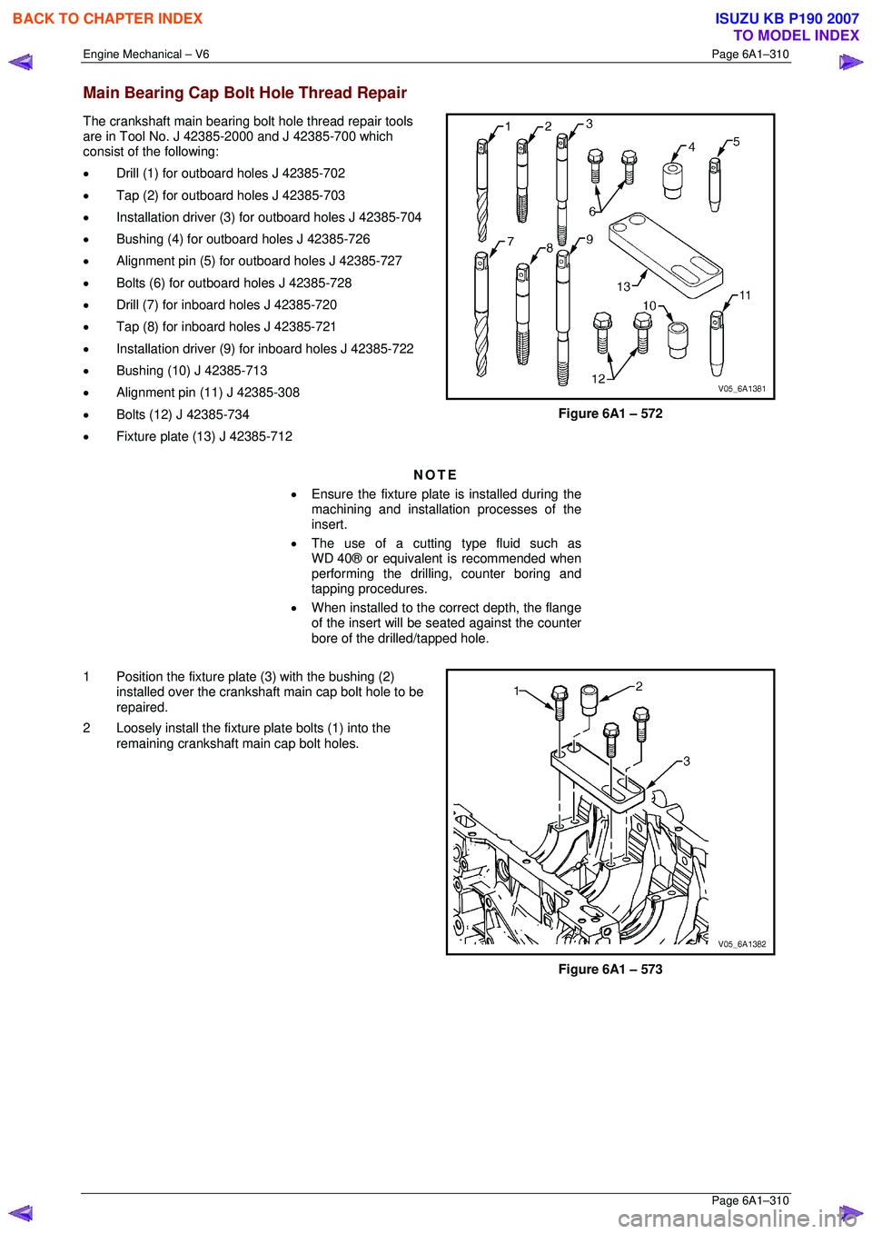
The crankshaft main bearing bolt hole thread repair tools
are in Tool No. J 42385-2000 and J 42385-700 which
consist of the following:
• Drill (1) for outboard holes J 42385-702
• Tap (2) for outboard holes J 42385-703
• Installation driver (3) for outboard holes J 42385-704
• Bushing (4) for outboard holes J 42385-726
• Alignment pin (5) for outboard holes J 42385-727
• Bolts (6) for outboard holes J 42385-728
• Drill (7) for inboard holes J 42385-720
• Tap (8) for inboard holes J 42385-721
• Installation driver (9) for inboard holes J 42385-722
• Bushing (10) J 42385-713
• Alignment pin (11) J 42385-308
• Bolts (12) J 42385-734
• Fixture plate (13) J 42385-712
Figure 6A1 – 572
NOTE
• Ensure the fixture plate is installed during the
machining and installation processes of the
insert.
• The use of a cutting type fluid such as
WD 40® or equivalent is recommended when
performing the drilling, counter boring and
tapping procedures.
• When installed to the correct depth, the flange
of the insert will be s eated against the counter
bore of the drilled/tapped hole.
1 Position the fixture plate (3) with the bushing (2) installed over the crankshaft main cap bolt hole to be
repaired.
2 Loosely install the fixture plate bolts (1) into the
remaining crankshaft main cap bolt holes.
Figure 6A1 – 573
BACK TO CHAPTER INDEX
TO MODEL INDEX
ISUZU KB P190 2007
Page 3093 of 6020
Engine Mechanical – V6 Page 6A1–316
Page 6A1–316
NOTE
• Ensure the fixture plate is installed during the
machining and installation processes of the
insert.
• The use of a cutting type fluid such as
WD 40® or equivalent is recommended when
performing the drilling, counter boring and
tapping procedures.
• When installed to the correct depth, the flange
of the insert will be s eated against the counter
bore of the drilled/tapped hole.
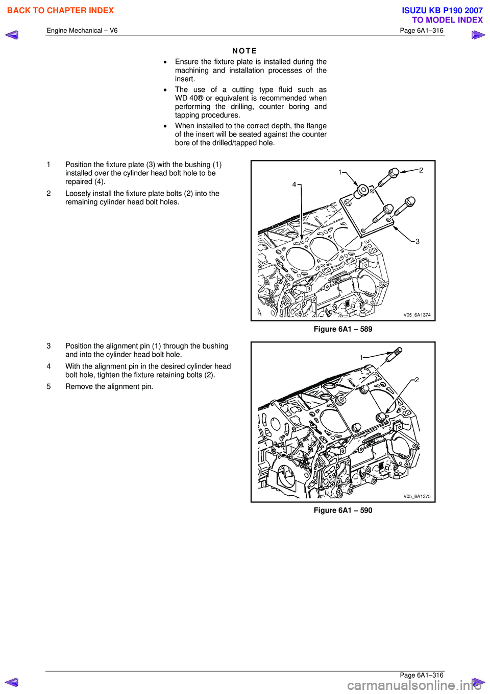
1 Position the fixture plate (3) with the bushing (1) installed over the cylinder head bolt hole to be
repaired (4).
2 Loosely install the fixture plate bolts (2) into the
remaining cylinder head bolt holes.
Figure 6A1 – 589
3 Position the alignment pin (1) through the bushing and into the cylinder head bolt hole.
4 With the alignment pin in the desired cylinder head bolt hole, tighten the fixture retaining bolts (2).
5 Remove the alignment pin.
Figure 6A1 – 590
BACK TO CHAPTER INDEX
TO MODEL INDEX
ISUZU KB P190 2007
Page 3125 of 6020
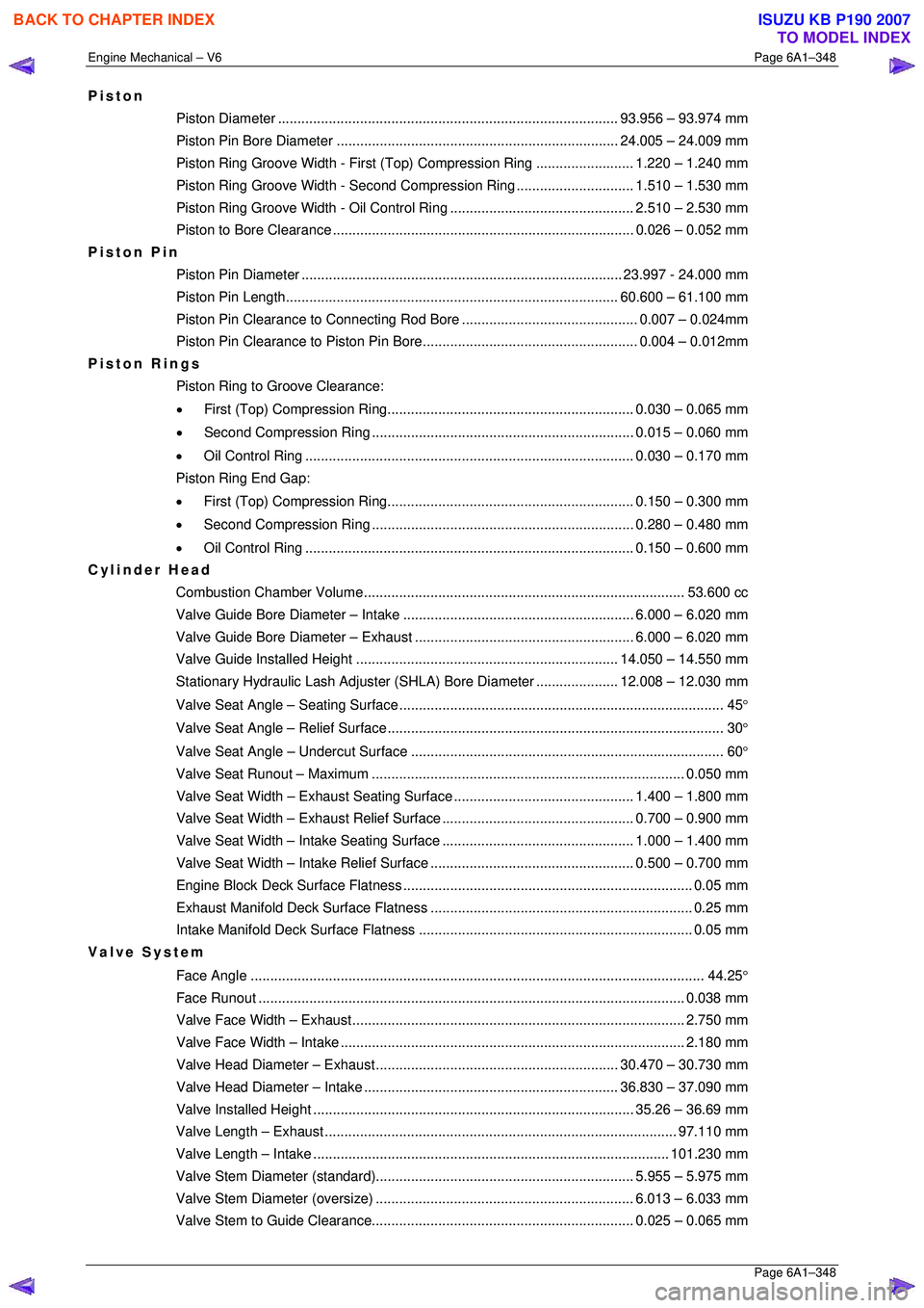
Engine Mechanical – V6 Page 6A1–348
Page 6A1–348
Piston
Piston Diameter ....................................................................................... 93. 956 – 93.974 mm
Piston Pin Bore Diame ter ........................................................................ 24.005 – 24.009 mm
Piston Ring Groove Width - First (Top) Compression Ring ......................... 1.220 – 1.240 mm
Piston Ring Groove Width - Second Compression Ring.............................. 1. 510 – 1.530 mm
Piston Ring Groove Width - Oil Control Ring ............................................... 2. 510 – 2.530 mm
Piston to Bore Clear ance ............................................................................. 0.026 – 0.052 mm
Piston Pin
Piston Pin Diamet er .................................................................................. 23.997 - 24.000 mm
Piston Pin Length ..................................................................................... 60. 600 – 61.100 mm
Piston Pin Clearance to Connec ting Rod Bore............................................. 0. 007 – 0.024mm
Piston Pin Clearance to Pist on Pin Bore....................................................... 0. 004 – 0.012mm
Piston Rings
Piston Ring to Groove Clearance:
• First (Top) Compression Ring............................................................... 0. 030 – 0.065 mm
• Second Compression Ring ................................................................... 0.015 – 0.060 mm
• Oil Control Ring .................................................................................... 0. 030 – 0.170 mm
Piston Ring End Gap:
• First (Top) Compression Ring............................................................... 0. 150 – 0.300 mm
• Second Compression Ring ................................................................... 0.280 – 0.480 mm
• Oil Control Ring .................................................................................... 0. 150 – 0.600 mm
Cylinder Head
Combustion Chambe r Volume.................................................................................. 53. 600 cc
Valve Guide Bore Diameter – Intake ........................................................... 6.000 – 6.020 mm
Valve Guide Bore Diameter – Exhaust ........................................................ 6.000 – 6.020 mm
Valve Guide Installed Height................................................................... 14. 050 – 14.550 mm
Stationary Hydraulic Lash Adjuster (S HLA) Bore Diameter .....................12.008 – 12.030 mm
Valve Seat Angle – Seating Surface ................................................................................... 45 °
Valve Seat Angle – Relief Surface...................................................................................... 30 °
Valve Seat Angle – Un dercut Surface ................................................................................ 60 °
Valve Seat Runout – Maximum................................................................................ 0. 050 mm
Valve Seat Width – Exhaust S eating Surface.............................................. 1. 400 – 1.800 mm
Valve Seat Width – Exhaust Re lief Surface................................................. 0. 700 – 0.900 mm
Valve Seat Width – Intake Se ating Surface................................................. 1. 000 – 1.400 mm
Valve Seat Width – Intake Relief Surface.................................................... 0. 500 – 0.700 mm
Engine Block Deck Surf ace Flatness .......................................................................... 0. 05 mm
Exhaust Manifold Deck Su rface Flatness ................................................................... 0. 25 mm
Intake Manifold Deck Su rface Flatness ...................................................................... 0. 05 mm
Valve System
Face Angle .................................................................................................................... 4 4.25°
Face Run out ............................................................................................................. 0.038 mm
Valve Face Width – Exhaust..................................................................................... 2. 750 mm
Valve Face Width – Intake........................................................................................ 2. 180 mm
Valve Head Diameter – Ex haust .............................................................. 30.470 – 30.730 mm
Valve Head Diameter – Intake ................................................................. 36. 830 – 37.090 mm
Valve Installed He ight .................................................................................. 35.26 – 36.69 mm
Valve Length – Exhaust.......................................................................................... 97. 110 mm
Valve Length – Intake ........................................................................................... 101.230 mm
Valve Stem Diameter (s tandard).................................................................. 5. 955 – 5.975 mm
Valve Stem Diameter (o versize).................................................................. 6.013 – 6.033 mm
Valve Stem to Guide Clearance................................................................... 0. 025 – 0.065 mm
BACK TO CHAPTER INDEX
TO MODEL INDEX
ISUZU KB P190 2007
Page 3128 of 6020
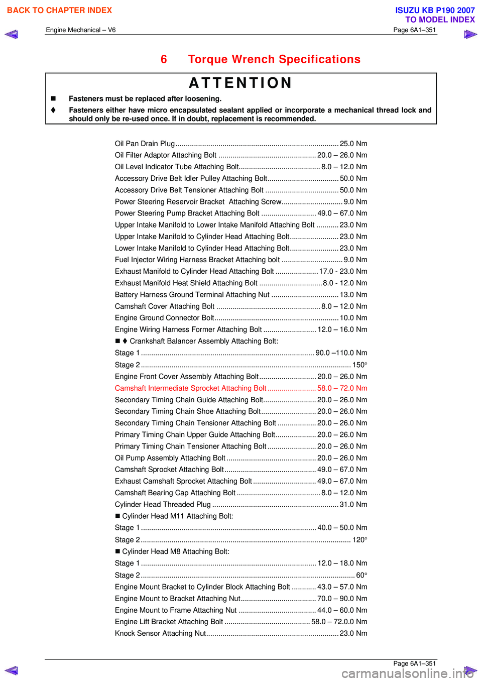
Engine Mechanical – V6 Page 6A1–351
Page 6A1–351
6 Torque Wrench Specifications
ATTENTION
�„ Fasteners must be replaced after loosening.
Fasteners either have micro encapsulated sealant a pplied or incorporate a mechanical thread lock and
should only be re-used once. If in doubt, replacement is recommended.
Oil Pan Drain Plug ................................................................................ 25.0 Nm
Oil Filter Adaptor Attach ing Bolt................................................ 20.0 – 26.0 Nm
Oil Level Indicator Tube Atta ching Bolt........................................ 8.0 – 12.0 Nm
Accessory Drive Belt Idler Pu lley Attaching Bolt................................... 50.0 Nm
Accessory Drive Belt Tensio ner Attaching Bolt .................................... 50.0 Nm
Power Steering Reserv oir Bracket Attaching Screw.............................. 9.0 Nm
Power Steering Pump Bracket A ttaching Bolt ........................... 49. 0 – 67.0 Nm
Upper Intake Manifold to Lower Intake Manifold Attaching Bolt ........... 23.0 Nm
Upper Intake Manifold to Cylinder Head Attaching Bolt........................ 23.0 Nm
Lower Intake Manifold to Cylind er Head Attaching Bolt........................ 23.0 Nm
Fuel Injector Wiring Harness Br acket Attaching bolt .............................. 9. 0 Nm
Exhaust Manifold to Cylinder He ad Attaching Bolt..................... 17.0 - 23.0 Nm
Exhaust Manifold Heat Shield Attaching Bolt ............................... 8.0 - 12.0 Nm
Battery Harness Ground Terminal Attaching Nut ................................. 13. 0 Nm
Camshaft Cover Attachi ng Bolt................................................... 8.0 – 12.0 Nm
Engine Ground Connec tor Bolt............................................................. 10.0 Nm
Engine Wiring Harness Former A ttaching Bolt .......................... 12.0 – 16.0 Nm
�„ Crankshaft Balancer A ssembly Attaching Bolt:
Stage 1 ..................................................................................... 90.0 –110.0 Nm
Stage 2 ....................................................................................................... 150 °
Engine Front Cover Assembly A ttaching Bolt ............................ 20. 0 – 26.0 Nm
Camshaft Intermediate Sprocket Attaching Bolt ........................ 58. 0 – 72.0 Nm
Secondary Timing Chai n Guide Attaching Bolt.......................... 20.0 – 26.0 Nm
Secondary Timing Chai n Shoe Attaching Bolt ........................... 20.0 – 26.0 Nm
Secondary Timing Chain Tensioner Attachi ng Bolt ................... 20.0 – 26.0 Nm
Primary Timing Chain Upper Gui de Attaching Bolt.................... 20.0 – 26.0 Nm
Primary Timing Chain Tensioner Attaching Bolt........................ 20. 0 – 26.0 Nm
Oil Pump Assembly Attach ing Bolt............................................ 20.0 – 26.0 Nm
Camshaft Sprocket Attachi ng Bolt............................................. 49.0 – 67.0 Nm
Exhaust Camshaft Sprocket Atta ching Bolt............................... 49.0 – 67.0 Nm
Camshaft Bearing Cap Attach ing Bolt......................................... 8.0 – 12.0 Nm
Cylinder Head Thr eaded Plug.............................................................. 31.0 Nm
�„ Cylinder Head M11 Attaching Bolt:
Stage 1 ...................................................................................... 40.0 – 50.0 Nm
Stage 2 ....................................................................................................... 120 °
�„ Cylinder Head M8 Attaching Bolt:
Stage 1 ...................................................................................... 12.0 – 18.0 Nm
Stage 2 ......................................................................................................... 60 °
Engine Mount Bracket to Cylinder Bl ock Attaching Bolt............ 43.0 – 57.0 Nm
Engine Mount to Bracket Atta ching Nut..................................... 70.0 – 90.0 Nm
Engine Mount to Frame Atta ching Nut...................................... 44.0 – 60.0 Nm
Engine Lift Bracket Attachi ng Bolt.......................................... 58.0 – 72.0.0 Nm
Knock Sensor Attach ing Nut................................................................. 23.0 Nm
BACK TO CHAPTER INDEX
TO MODEL INDEX
ISUZU KB P190 2007
Page 3136 of 6020
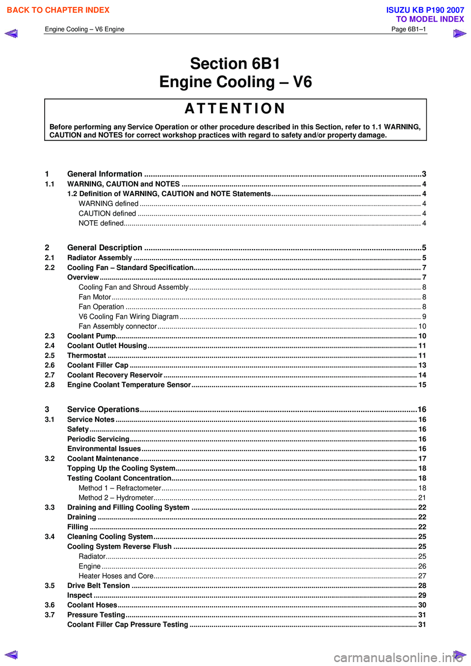
Engine Cooling – V6 Engine Page 6B1–1
Section 6B1
Engine Cooling – V6
ATTENTION
Before performing any Service Operation or other procedure described in this Section, refer to 1.1 WARNING,
CAUTION and NOTES for correct workshop practices with regard to safety and/or property damage.
1 General Information ............................................................................................................ ...................3
1.1 WARNING, CAUTION and NOTES ..................................................................................................... ................... 4
1.2 Definition of WARNING, CAUTION and NOTE Statements ......................................................................... .. 4
WARNING defined ............................................................................................................................................. 4
CAUTION defined .............................................................................................................................................. 4
NOTE defined..................................................................................................................................................... 4
2 General Description ............................................................................................................ ...................5
2.1 Radiator Assembly .............................................................................................................. .................................. 5
2.2 Cooling Fan – Standard Specification.................................................................................................................. 7
Overview ................................................................................................................................................................. 7
Cooling Fan and Shroud Assembly ................................................................................................ .................... 8
Fan Motor ........................................................................................................................................................... 8
Fan Operation .................................................................................................................. .................................. 8
V6 Cooling Fan Wiring Diagram .................................................................................................. ....................... 9
Fan Assembly connector .................................................................................................................................. 10
2.3 Coolant Pump....................................................................................................................................................... 10
2.4 Coolant Outlet Housing ......................................................................................................... .............................. 11
2.5 Thermostat ........................................................................................................................................................... 11
2.6 Coolant Filler Cap ............................................................................................................. ................................... 13
2.7 Coolant Recovery Reservoir ..................................................................................................... .......................... 14
2.8 Engine Coolant Temperature Sensor .............................................................................................. ................... 15
3 Service Operations ...............................................................................................................................16
3.1 Service Notes ....................................................................................................................................................... 16
Safety .................................................................................................................................................................... 16
Periodic Servicing............................................................................................................. ................................... 16
Environmental Issues ........................................................................................................... ............................... 16
3.2 Coolant Maintenance ........................................................................................................................................... 17
Topping Up the Cooling System.................................................................................................. ....................... 18
Testing Coolant Concentration........................................................................................................................... 18
Method 1 – Refractometer................................................................................................................................ 18
Method 2 – Hydrometer.................................................................................................................................... 21
3.3 Draining and Filling Cooling System ............................................................................................ ..................... 22
Draining ................................................................................................................................................................ 22
Filling .................................................................................................................................................................... 22
3.4 Cleaning Cooling System ........................................................................................................ ............................ 25
Cooling System Reverse Flush ................................................................................................... ....................... 25
Radiator............................................................................................................................................................ 25
Engine .............................................................................................................................................................. 26
Heater Hoses and Core.......................................................................................................... .......................... 27
3.5 Drive Belt Tension ............................................................................................................................................... 28
Inspect .................................................................................................................................................................. 29
3.6 Coolant Hoses ...................................................................................................................................................... 30
3.7 Pressure Testing ............................................................................................................... ................................... 31
Coolant Filler Cap Pressure Testing ............................................................................................ ...................... 31
BACK TO CHAPTER INDEX
TO MODEL INDEX
ISUZU KB P190 2007
Page 3137 of 6020
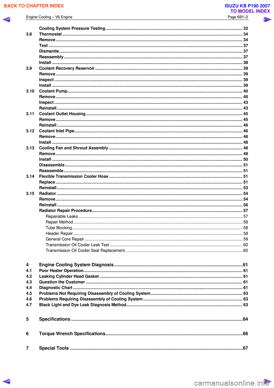
Engine Cooling – V6 Engine Page 6B1–2
Cooling System Pressure Testing ................................................................................................ ...................... 32
3.8 Thermostat ........................................................................................................................................................... 34
Remove ................................................................................................................................................................. 34
Test ....................................................................................................................................................................... 37
Dismantle ...................................................................................................................... ........................................ 37
Reassembly .......................................................................................................................................................... 37
Install .................................................................................................................................................................... 38
3.9 Coolant Recovery Reservoir ..................................................................................................... .......................... 39
Remove ................................................................................................................................................................. 39
Inspect .................................................................................................................................................................. 39
Install .................................................................................................................................................................... 39
3.10 Coolant Pump................................................................................................................... .................................... 40
Remove ................................................................................................................................................................. 40
Inspect .................................................................................................................................................................. 43
Reinstall ................................................................................................................................................................ 43
3.11 Coolant Outlet Housing ......................................................................................................... .............................. 45
Remove ................................................................................................................................................................. 45
Reinstall ................................................................................................................................................................ 46
3.12 Coolant Inlet Pipe............................................................................................................. .................................... 46
Remove ................................................................................................................................................................. 46
Install .................................................................................................................................................................... 48
3.13 Cooling Fan and Shroud Assembly ................................................................................................ ................... 48
Remove ................................................................................................................................................................. 48
Install .................................................................................................................................................................... 50
Disassemble ......................................................................................................................................................... 51
Reassemble .......................................................................................................................................................... 51
3.14 Flexible Transmission Cooler Hose .............................................................................................. ..................... 51
Replace ................................................................................................................................................................. 51
Reinstall ................................................................................................................................................................ 53
3.15 Radiator ....................................................................................................................... ......................................... 54
Remove ......................................................................................................................... ........................................ 54
Reinstall ................................................................................................................................................................ 56
Radiator Repair Procedure...................................................................................................... ............................ 57
Repairable Leaks ............................................................................................................................................. 57
Repair Method.................................................................................................................................................. 58
Tube Blocking................................................................................................................................................... 58
Header Repair .................................................................................................................. ................................ 58
General Core Repair ............................................................................................................ ............................ 59
Transmission Oil Cooler Leak Test .............................................................................................. .................... 60
Transmission Oil Cooler Seal Replacement. ...................................................................................... .............. 60
4 Engine Cooling System Diagnosis .....................................................................................................61
4.1 Poor Heater Operation......................................................................................................................................... 61
4.2 Leaking Cylinder Head Gasket ................................................................................................... ........................ 61
4.3 Question the Customer ....................................................................................................................................... 61
4.4 Diagnostic Chart .................................................................................................................................................. 61
4.5 Problems Not Requiring Disassembly of Cooling System ........................................................................... .... 63
4.6 Problems Requiring Disassembly of Cooling System ...................................................................................... 63
4.7 Black Light and Dye Leak Diagnosis Method .................................................................................................... 63
5 Specifications .......................................................................................................................................64
6 Torque Wrench Specifications................................................................................................... .........66
7 Special Tools ........................................................................................................................................67
BACK TO CHAPTER INDEX
TO MODEL INDEX
ISUZU KB P190 2007