Page 1174 of 3061

TROUBLE DIAGNOSIS
EC-91
< SERVICE INFORMATION >
C
D
E
F
G
H
I
J
K
L
MA
EC
N
P O
1 - 6: The numbers refer to the order of inspection.
(continued on next page)
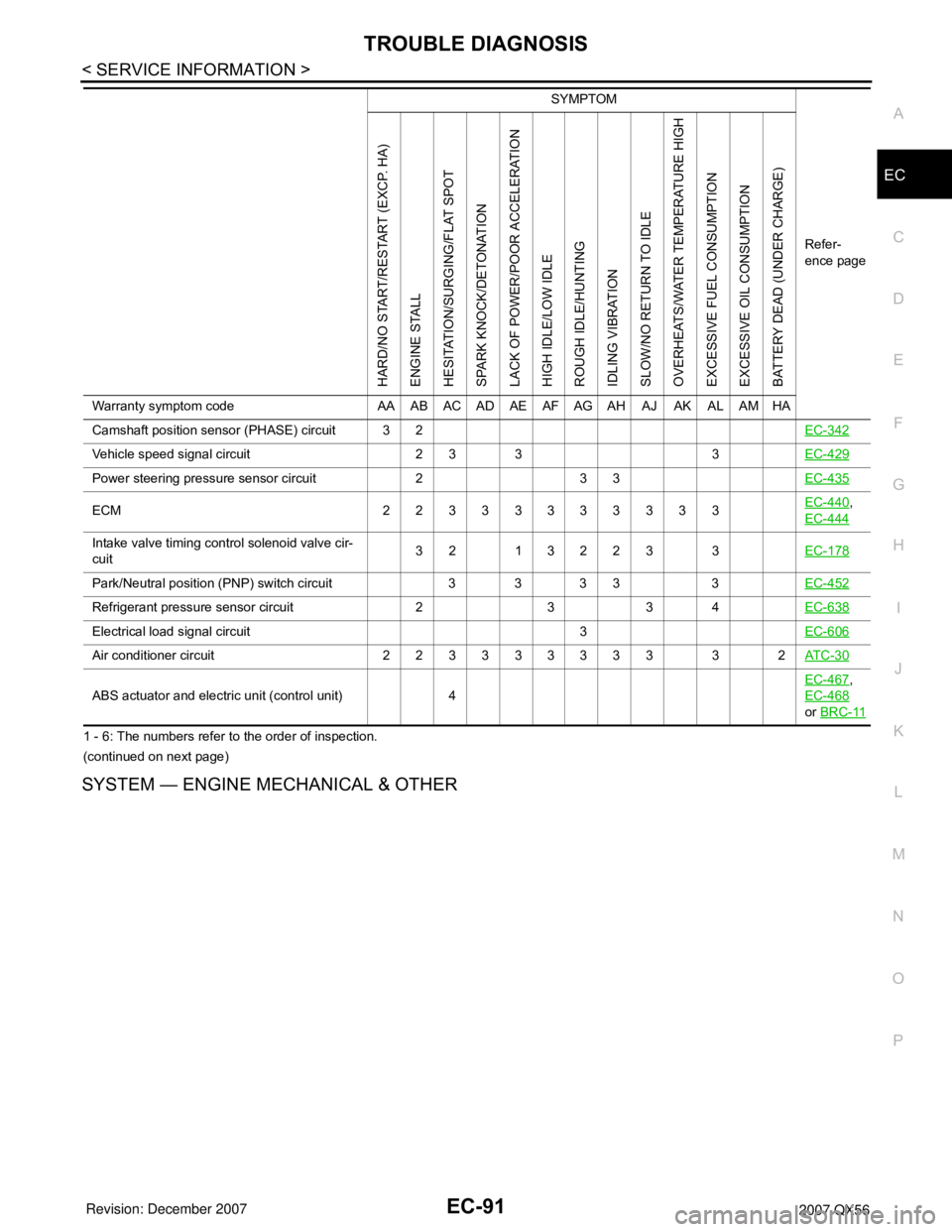
SYSTEM — ENGINE MECHANICAL & OTHER
Camshaft position sensor (PHASE) circuit 3 2EC-342
Vehicle speed signal circuit 2 3 3 3EC-429
Power steering pressure sensor circuit 2 3 3EC-435
ECM 22333333333EC-440,
EC-444
Intake valve timing control solenoid valve cir-
cuit32 13223 3EC-178
Park/Neutral position (PNP) switch circuit 3 3 3 3 3EC-452
Refrigerant pressure sensor circuit 2 3 3 4EC-638
Electrical load signal circuit 3EC-606
Air conditioner circuit 223333333 3 2AT C - 3 0
ABS actuator and electric unit (control unit) 4EC-467
,
EC-468
or BRC-11
SYMPTOM
Refer-
ence page
HARD/NO START/RESTART (EXCP. HA)
ENGINE STALL
HESITATION/SURGING/FLAT SPOT
SPARK KNOCK/DETONATION
LACK OF POWER/POOR ACCELERATION
HIGH IDLE/LOW IDLE
ROUGH IDLE/HUNTING
IDLING VIBRATION
SLOW/NO RETURN TO IDLE
OVERHEATS/WATER TEMPERATURE HIGH
EXCESSIVE FUEL CONSUMPTION
EXCESSIVE OIL CONSUMPTION
BATTERY DEAD (UNDER CHARGE)
Warranty symptom code AA AB AC AD AE AF AG AH AJ AK AL AM HA
Page 1175 of 3061

EC-92
< SERVICE INFORMATION >
TROUBLE DIAGNOSIS
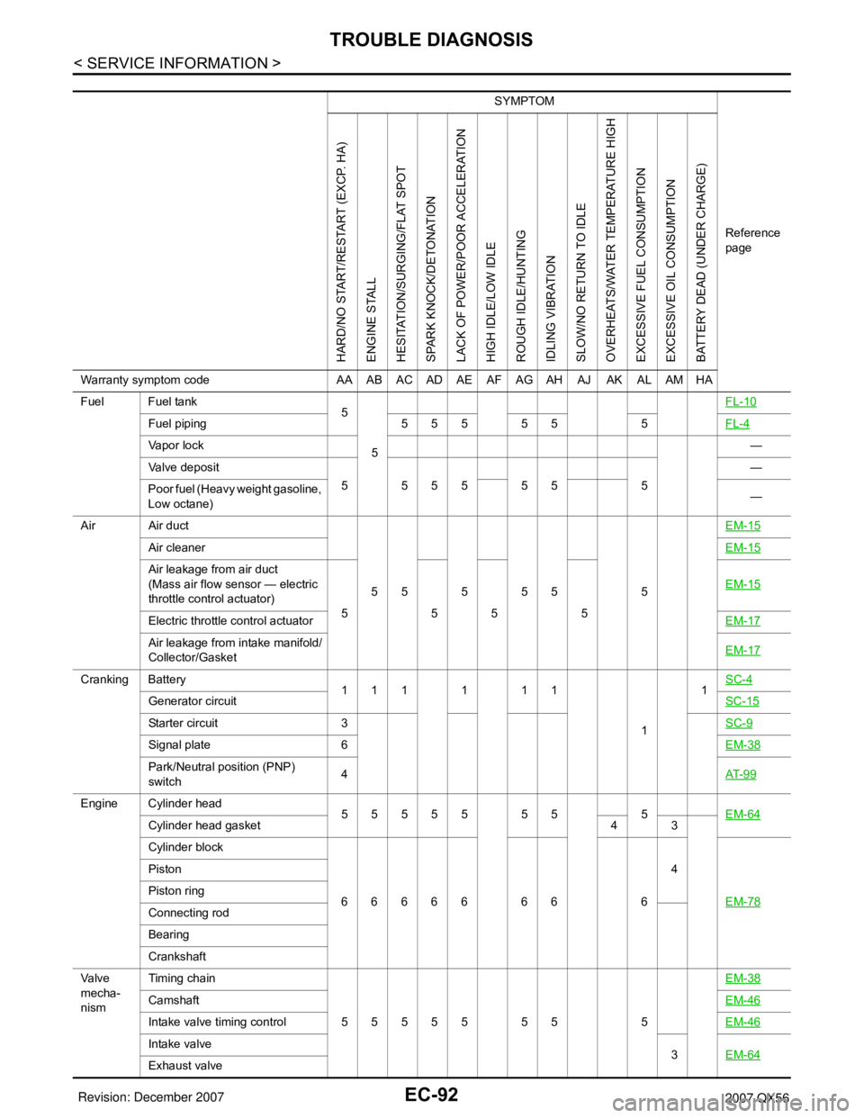
SYMPTOM
Reference
page
HARD/NO START/RESTART (EXCP. HA)
ENGINE STALL
HESITATION/SURGING/FLAT SPOT
SPARK KNOCK/DETONATION
LACK OF POWER/POOR ACCELERATION
HIGH IDLE/LOW IDLE
ROUGH IDLE/HUNTING
IDLING VIBRATION
SLOW/NO RETURN TO IDLE
OVERHEATS/WATER TEMPERATURE HIGH
EXCESSIVE FUEL CONSUMPTION
EXCESSIVE OIL CONSUMPTION
BATTERY DEAD (UNDER CHARGE)
Warranty symptom code AA AB AC AD AE AF AG AH AJ AK AL AM HA
Fuel Fuel tank
5
5FL-10
Fuel piping 5 5 5 5 5 5FL-4
Va p o r l o c k—
Valve deposit
5 555 55 5—
Poor fuel (Heavy weight gasoline,
Low octane)—
Air Air duct
55555 5EM-15
Air cleanerEM-15
Air leakage from air duct
(Mass air flow sensor — electric
throttle control actuator)
5555EM-15
Electric throttle control actuatorEM-17
Air leakage from intake manifold/
Collector/GasketEM-17
Cranking Battery
111111
11SC-4
Generator circuitSC-15
Starter circuit 3SC-9
Signal plate 6EM-38
Park/Neutral position (PNP)
switch4AT- 9 9
Engine Cylinder head
55555 55 5EM-64
Cylinder head gasket 4 3
Cylinder block
66666 66 64
EM-78
Piston
Piston ring
Connecting rod
Bearing
Crankshaft
Va l v e
mecha-
nismTiming chain
55555 55 5EM-38
CamshaftEM-46
Intake valve timing controlEM-46
Intake valve
3EM-64
Exhaust valve
Page 1176 of 3061

TROUBLE DIAGNOSIS
EC-93
< SERVICE INFORMATION >
C
D
E
F
G
H
I
J
K
L
MA
EC
N
P O
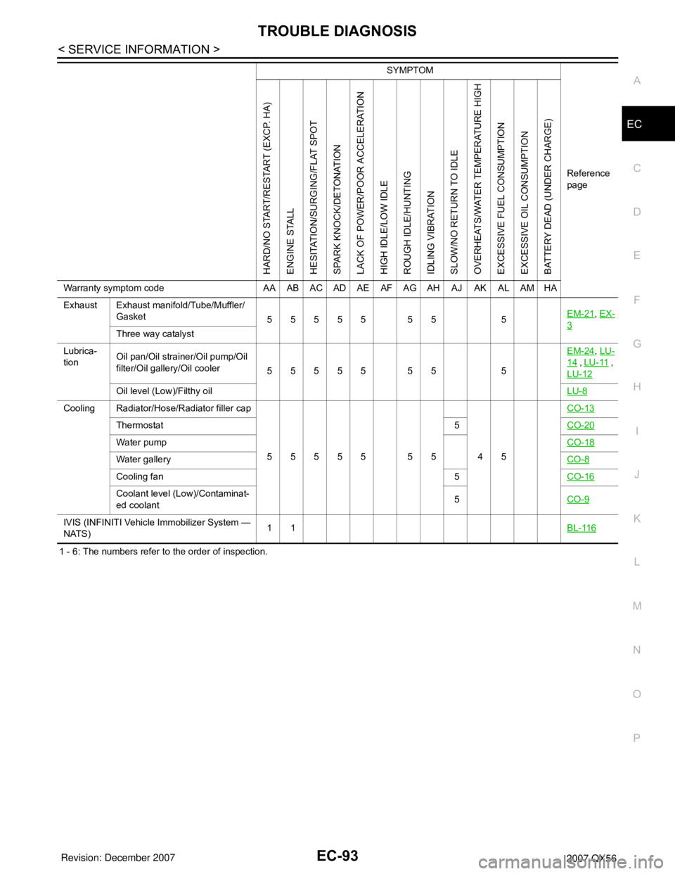
1 - 6: The numbers refer to the order of inspection.Exhaust Exhaust manifold/Tube/Muffler/
Gasket
55555 55 5EM-21
, EX-
3Three way catalyst
Lubrica-
tionOil pan/Oil strainer/Oil pump/Oil
filter/Oil gallery/Oil cooler
55555 55 5EM-24
, LU-
14 , LU-11 ,
LU-12
Oil level (Low)/Filthy oilLU-8
Cooling Radiator/Hose/Radiator filler cap
55555 55 45CO-13
Thermostat 5CO-20
Water pumpCO-18
Water galleryCO-8
Cooling fan 5CO-16
Coolant level (Low)/Contaminat-
ed coolant5CO-9
IVIS (INFINITI Vehicle Immobilizer System —
NATS)11BL-116
SYMPTOM
Reference
page
HARD/NO START/RESTART (EXCP. HA)
ENGINE STALL
HESITATION/SURGING/FLAT SPOT
SPARK KNOCK/DETONATION
LACK OF POWER/POOR ACCELERATION
HIGH IDLE/LOW IDLE
ROUGH IDLE/HUNTING
IDLING VIBRATION
SLOW/NO RETURN TO IDLE
OVERHEATS/WATER TEMPERATURE HIGH
EXCESSIVE FUEL CONSUMPTION
EXCESSIVE OIL CONSUMPTION
BATTERY DEAD (UNDER CHARGE)
Warranty symptom code AA AB AC AD AE AF AG AH AJ AK AL AM HA
Page 1177 of 3061

EC-94
< SERVICE INFORMATION >
TROUBLE DIAGNOSIS
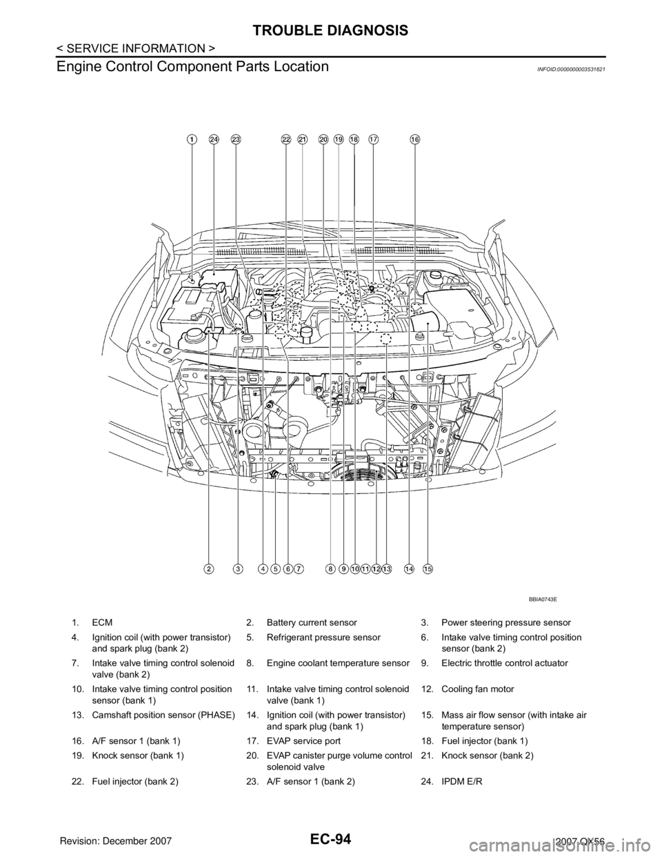
Engine Control Component Parts Location
INFOID:0000000003531621
1. ECM 2. Battery current sensor 3. Power steering pressure sensor
4. Ignition coil (with power transistor)
and spark plug (bank 2)5. Refrigerant pressure sensor 6. Intake valve timing control position
sensor (bank 2)
7. Intake valve timing control solenoid
valve (bank 2)8. Engine coolant temperature sensor 9. Electric throttle control actuator
10. Intake valve timing control position
sensor (bank 1)11. Intake valve timing control solenoid
valve (bank 1)12. Cooling fan motor
13. Camshaft position sensor (PHASE) 14. Ignition coil (with power transistor)
and spark plug (bank 1)15. Mass air flow sensor (with intake air
temperature sensor)
16. A/F sensor 1 (bank 1) 17. EVAP service port 18. Fuel injector (bank 1)
19. Knock sensor (bank 1) 20. EVAP canister purge volume control
solenoid valve21. Knock sensor (bank 2)
22. Fuel injector (bank 2) 23. A/F sensor 1 (bank 2) 24. IPDM E/R
BBIA0743E
Page 1178 of 3061
TROUBLE DIAGNOSIS
EC-95
< SERVICE INFORMATION >
C
D
E
F
G
H
I
J
K
L
MA
EC
N
P O
1. Body ground (view with battery re-
moved)2. Body ground (view with battery re-
moved)3. Body ground
4. No. 1 ignition coil 5. Engine ground 6. Mass air flow sensor (with intake air
temperature sensor)
7. IPDM E/R 8. Battery 9. Radiator hose
10. Camshaft position sensor (PHASE) 11. Electric throttle control actuator
(view with intake air duct removed)12. Cooling fan motor harness connec-
tor
BBIA0778E
Page 1179 of 3061
EC-96
< SERVICE INFORMATION >
TROUBLE DIAGNOSIS
1. EVAP canister purge volume control
solenoid valve (view with engine
cover removed)2. EVAP service port (view with engine
cover removed)3. Crankshaft position sensor (POS)
(view from under the vehicle)
4. Engine oil pan (view from under the
vehicle)5. Condenser-1 6. Brake fluid reservoir
7. EVAP canister (view with fuel tank
removed)8. EVAP control system pressure sen-
sor (view with fuel tank removed)9. EVAP canister vent control valve
(view with fuel tank removed)
10. Rear suspension member (view with
fuel tank removed)11. Refrigerant pressure sensor (view
with hood open)12. Intake valve timing control position
sensor (bank 2) (view with engine
cover and intake air duct removed)
BBIA0783E
Page 1180 of 3061
TROUBLE DIAGNOSIS
EC-97
< SERVICE INFORMATION >
C
D
E
F
G
H
I
J
K
L
MA
EC
N
P O
13. Intake valve timing control position
sensor (bank 1) (view with engine
cover and intake air duct removed)14. Intake valve timing control solenoid
valve (bank 2) (view with engine cov-
er and intake air duct removed)15. Drive belt (view with engine cover
and intake air duct removed)
16. Radiator hose (view with engine cov-
er and intake air duct removed)17. Intake valve timing control solenoid
valve (bank 1) (view with engine cov-
er and intake air duct removed)
1. Knock sensor (bank 1) (view with en-
gine removed)2. Knock sensor (bank 2) (view with en-
gine removed)3. Battery current sensor
4. Power steering pressure sensor 5. Power steering fluid reservoir 6. Intake manifold
7. Engine coolant temperature sensor 8. Ignition coils (with power transistor) 9. Ignition coil (with power transistor)
10. Injector harness connectors (bank 2) 11. Injector harness connectors (bank 1)
BBIA0774E
Page 1203 of 3061

EC-120
< SERVICE INFORMATION >
TROUBLE DIAGNOSIS
*: Leaving cooling fan OFF with CONSULT-II while engine is running may cause the engine to overheat.
DTC & SRT CONFIRMATION MODE
SRT STATUS Mode
For details, refer to EC-49, "Emission-related Diagnostic Information".
SRT WORK SUPPORT Mode
This mode enables a technician to drive a vehicle to set the SRT while monitoring the SRT status.
DTC WORK SUPPORT Mode
TEST ITEM CONDITION JUDGEMENT CHECK ITEM (REMEDY)
FUEL INJEC-
TION• Engine: Return to the original
trouble condition
• Change the amount of fuel injec-
tion using CONSULT-II.If trouble symptom disappears, see
CHECK ITEM.• Harness and connectors
• Fuel injector
• Air fuel ratio (A/F) sensor 1
IGNITION TIM-
ING• Engine: Return to the original
trouble condition
• Timing light: Set
• Retard the ignition timing using
CONSULT-II.If trouble symptom disappears, see
CHECK ITEM.• Perform Idle Air Volume Learning.
POWER BAL-
ANCE• Engine: After warming up, idle the
engine.
• A/C switch: OFF
• Selector lever: P or N
• Cut off each injector signal one at
a time using CONSULT-II.Engine runs rough or dies.• Harness and connectors
• Compression
• Fuel injector
• Power transistor
•Spark plug
• Ignition coil
COOLING FAN*• Ignition switch: ON
• Turn the cooling fan HI and OFF
using CONSULT-II.Cooling fan moves and stops.• Harness and connectors
• Cooling fan motor
• IPDM E/R
ENG COOLANT
TEMP• Engine: Return to the original
trouble condition
• Change the engine coolant tem-
perature using CONSULT-II.If trouble symptom disappears, see
CHECK ITEM.• Harness and connectors
• Engine coolant temperature sen-
sor
• Fuel injector
FUEL PUMP RE-
LAY• Ignition switch: ON
(Engine stopped)
• Turn the fuel pump relay ON and
OFF using CONSULT-II and lis-
ten to operating sound.Fuel pump relay makes the operat-
ing sound.• Harness and connectors
•Fuel pump relay
PURG VOL
CONT/V• Engine: After warming up, run en-
gine at 1,500 rpm.
• Change the EVAP canister purge
volume control solenoid valve
opening percent using CON-
SULT-II.Engine speed changes according to
the opening percent.• Harness and connectors
• Solenoid valve
FUEL/T TEMP
SEN• Change the fuel tank temperature using CONSULT-II.
VENT CON-
TROL/V• Ignition switch: ON
(Engine stopped)
• Turn solenoid valve ON and OFF
with the CONSULT-II and listen to
operating sound.Solenoid valve makes an operating
sound.• Harness and connectors
• Solenoid valve
V/T ASSIGN AN-
GLE• Engine: Return to the original
trouble condition
• Change intake valve timing using
CONSULT-II.If trouble symptom disappears, see
CHECK ITEM.• Harness and connectors
• Intake valve timing control sole-
noid valve
ALTERNATOR
DUTY•Engine: Idle
• Change duty ratio using CON-
SULT-II.Battery voltage changes.• Harness and connectors
• IPDM E/R
•Alternator