2007 INFINITI QX56 battery
[x] Cancel search: batteryPage 2809 of 3061
FRONT PASSENGER AIR BAG MODULE
SRS-39
< SERVICE INFORMATION >
C
D
E
F
G
I
J
K
L
MA
B
SRS
N
O
P
FRONT PASSENGER AIR BAG MODULE
Removal and InstallationINFOID:0000000003532875
The passenger air bag module originally installed in the vehicle uses direct-connect style harness connectors.
Service replacement passenger air bag modules use tab-locking style harness connectors. If the passenger
air bag module is replaced or if the direct-connect harness connectors are damaged, the vehicle wiring har-
ness must be modified to allow connection of the service replacement passenger air bag module. Refer to
"WIRING HARNESS MODIFICATION" for wiring harness modification procedure.
REMOVAL
CAUTION:
• Do not attempt to repair or replace damaged direct-connect front passenger air bag module connec-
tors. If a direct-connect harness connector is damaged, the front passenger air bag must be
replaced and the wiring harness modified.
• Before servicing SRS, turn the ignition switch off, disconnect both battery cables and wait at least 3
minutes.
• Always work from the side of or under front passenger air bag module.
1. Remove the glove box. Refer to IP-10
.
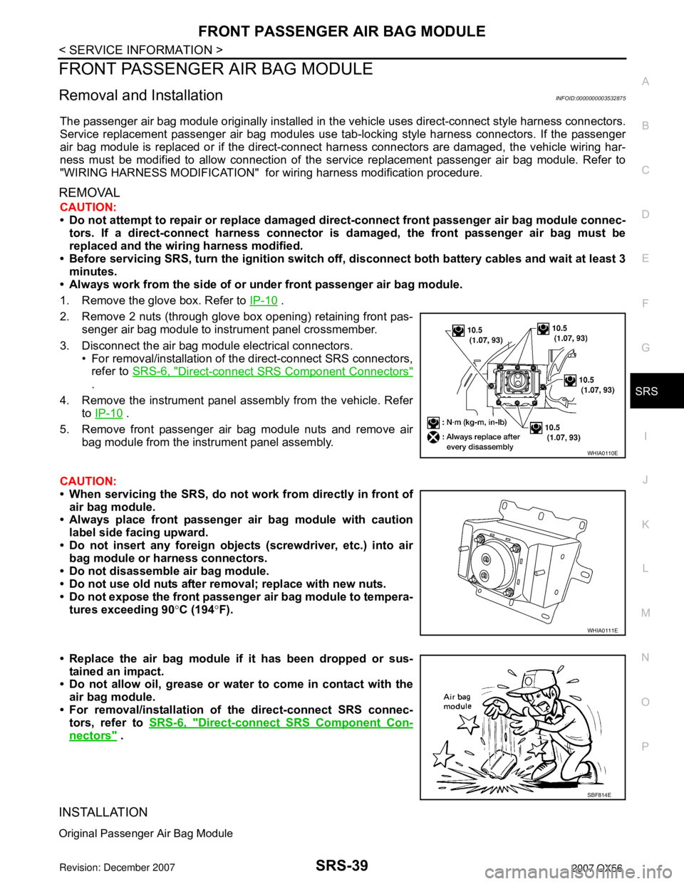
2. Remove 2 nuts (through glove box opening) retaining front pas-
senger air bag module to instrument panel crossmember.
3. Disconnect the air bag module electrical connectors.
• For removal/installation of the direct-connect SRS connectors,
refer to SRS-6, "
Direct-connect SRS Component Connectors"
.
4. Remove the instrument panel assembly from the vehicle. Refer
to IP-10
.
5. Remove front passenger air bag module nuts and remove air
bag module from the instrument panel assembly.
CAUTION:
• When servicing the SRS, do not work from directly in front of
air bag module.
• Always place front passenger air bag module with caution
label side facing upward.
• Do not insert any foreign objects (screwdriver, etc.) into air
bag module or harness connectors.
• Do not disassemble air bag module.
• Do not use old nuts after removal; replace with new nuts.
• Do not expose the front passenger air bag module to tempera-
tures exceeding 90°C (194°F).
• Replace the air bag module if it has been dropped or sus-
tained an impact.
• Do not allow oil, grease or water to come in contact with the
air bag module.
• For removal/installation of the direct-connect SRS connec-
tors, refer to SRS-6, "
Direct-connect SRS Component Con-
nectors" .
INSTALLATION
Original Passenger Air Bag Module
WHIA0110E
WHIA0111E
SBF814E
Page 2810 of 3061
SRS-40
< SERVICE INFORMATION >
FRONT PASSENGER AIR BAG MODULE
Installation is in the reverse order of removal.
• For removal/installation of the direct-connect SRS connectors, refer to SRS-6, "
Direct-connect SRS Compo-
nent Connectors".
CAUTION:
• Always work from the side of or under front passenger air bag module.
• After the work is completed, perform self-diagnosis to check that no malfunction is detected. Refer
to SRS-20, "
SRS Operation Check".
Service Replacement Passenger Air Bag Module
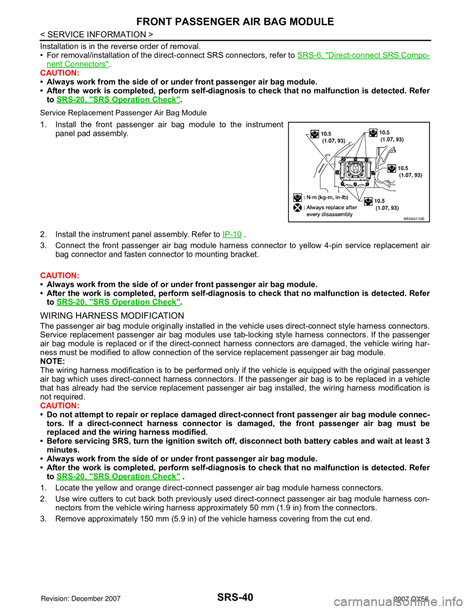
1. Install the front passenger air bag module to the instrument
panel pad assembly.
2. Install the instrument panel assembly. Refer to IP-10
.
3. Connect the front passenger air bag module harness connector to yellow 4-pin service replacement air
bag connector and fasten connector to mounting bracket.
CAUTION:
• Always work from the side of or under front passenger air bag module.
• After the work is completed, perform self-diagnosis to check that no malfunction is detected. Refer
to SRS-20, "
SRS Operation Check".
WIRING HARNESS MODIFICATION
The passenger air bag module originally installed in the vehicle uses direct-connect style harness connectors.
Service replacement passenger air bag modules use tab-locking style harness connectors. If the passenger
air bag module is replaced or if the direct-connect harness connectors are damaged, the vehicle wiring har-
ness must be modified to allow connection of the service replacement passenger air bag module.
NOTE:
The wiring harness modification is to be performed only if the vehicle is equipped with the original passenger
air bag which uses direct-connect harness connectors. If the passenger air bag is to be replaced in a vehicle
that has already had the service replacement passenger air bag installed, the wiring harness modification is
not required.
CAUTION:
• Do not attempt to repair or replace damaged direct-connect front passenger air bag module connec-
tors. If a direct-connect harness connector is damaged, the front passenger air bag must be
replaced and the wiring harness modified.
• Before servicing SRS, turn the ignition switch off, disconnect both battery cables and wait at least 3
minutes.
• Always work from the side of or under front passenger air bag module.
• After the work is completed, perform self-diagnosis to check that no malfunction is detected. Refer
to SRS-20, "
SRS Operation Check" .
1. Locate the yellow and orange direct-connect passenger air bag module harness connectors.
2. Use wire cutters to cut back both previously used direct-connect passenger air bag module harness con-
nectors from the vehicle wiring harness approximately 50 mm (1.9 in) from the connectors.
3. Remove approximately 150 mm (5.9 in) of the vehicle harness covering from the cut end.
WHIA0110E
Page 2812 of 3061
SRS-42
< SERVICE INFORMATION >
SIDE CURTAIN AIR BAG MODULE
SIDE CURTAIN AIR BAG MODULE
Removal and InstallationINFOID:0000000003532876
REMOVAL
CAUTION:
• Do not attempt to repair or replace damaged direct-connect SRS component connectors. If a direct-
connect harness connector is damaged, the harness must be replaced.
• Before servicing the SRS, turn the ignition switch off, disconnect both battery cables and wait at
least 3 minutes.
• When servicing the SRS, do not work from directly in front of air bag module.
1. Remove headlining. Refer to EI-37
.
2. Disconnect front and rear side curtain air bag module connectors.
• For removal/installation of the direct-connect SRS connectors, refer to SRS-6, "
Direct-connect SRS
Component Connectors" .
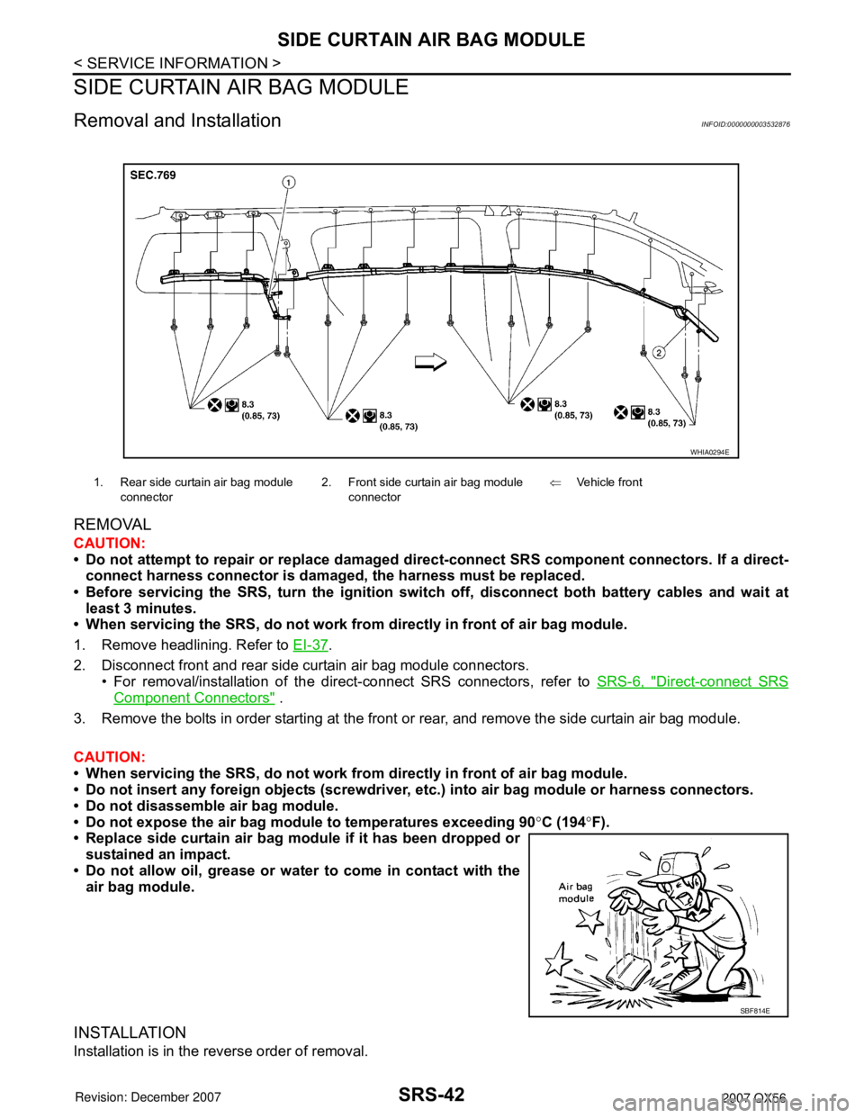
3. Remove the bolts in order starting at the front or rear, and remove the side curtain air bag module.
CAUTION:
• When servicing the SRS, do not work from directly in front of air bag module.
• Do not insert any foreign objects (screwdriver, etc.) into air bag module or harness connectors.
• Do not disassemble air bag module.
• Do not expose the air bag module to temperatures exceeding 90°C (194°F).
• Replace side curtain air bag module if it has been dropped or
sustained an impact.
• Do not allow oil, grease or water to come in contact with the
air bag module.
INSTALLATION
Installation is in the reverse order of removal.
1. Rear side curtain air bag module
connector2. Front side curtain air bag module
connector⇐Vehicle front
WHIA0294E
SBF814E
Page 2814 of 3061
SRS-44
< SERVICE INFORMATION >
CRASH ZONE SENSOR
CRASH ZONE SENSOR
Removal and InstallationINFOID:0000000003532877
REMOVAL
CAUTION:
• Before servicing the SRS, turn the ignition switch off, disconnect both battery cables and wait at
least 3 minutes.
1. Disconnect the negative and positive battery cables, then wait at least 3 minutes.
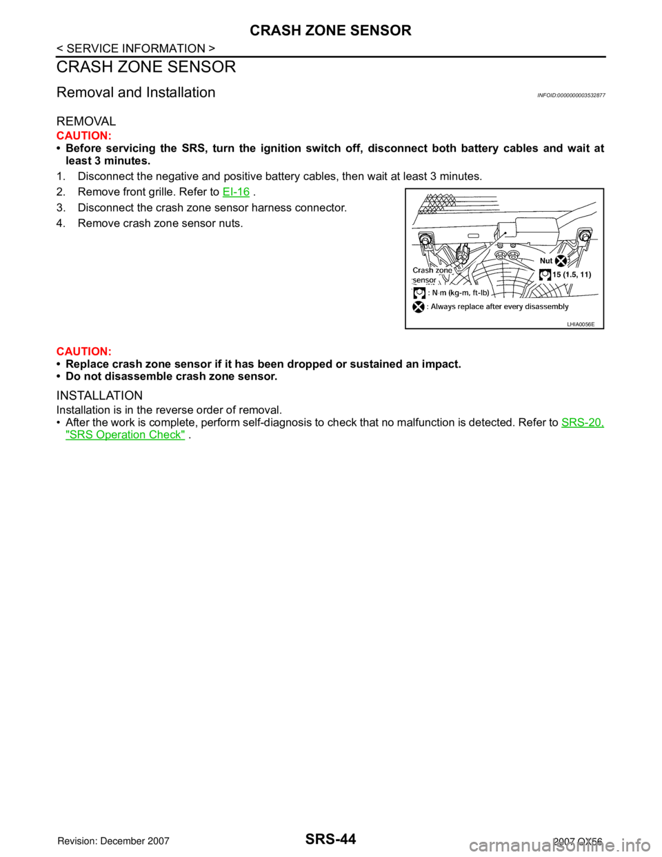
2. Remove front grille. Refer to EI-16
.
3. Disconnect the crash zone sensor harness connector.
4. Remove crash zone sensor nuts.
CAUTION:
• Replace crash zone sensor if it has been dropped or sustained an impact.
• Do not disassemble crash zone sensor.
INSTALLATION
Installation is in the reverse order of removal.
• After the work is complete, perform self-diagnosis to check that no malfunction is detected. Refer to SRS-20,
"SRS Operation Check" .
LHIA0056E
Page 2815 of 3061
SIDE AIR BAG (SATELLITE) SENSOR
SRS-45
< SERVICE INFORMATION >
C
D
E
F
G
I
J
K
L
MA
B
SRS
N
O
P
SIDE AIR BAG (SATELLITE) SENSOR
Removal and InstallationINFOID:0000000003532878
REMOVAL
CAUTION:
• Before servicing the SRS, turn the ignition switch off, disconnect both battery cables and wait at
least 3 minutes.
1. Disconnect the negative and positive battery cables, then wait at least 3 minutes.
2. Remove seat belt pre-tensioner. Refer to SB-3, "
Removal and
Installation of Front Seat Belt" .
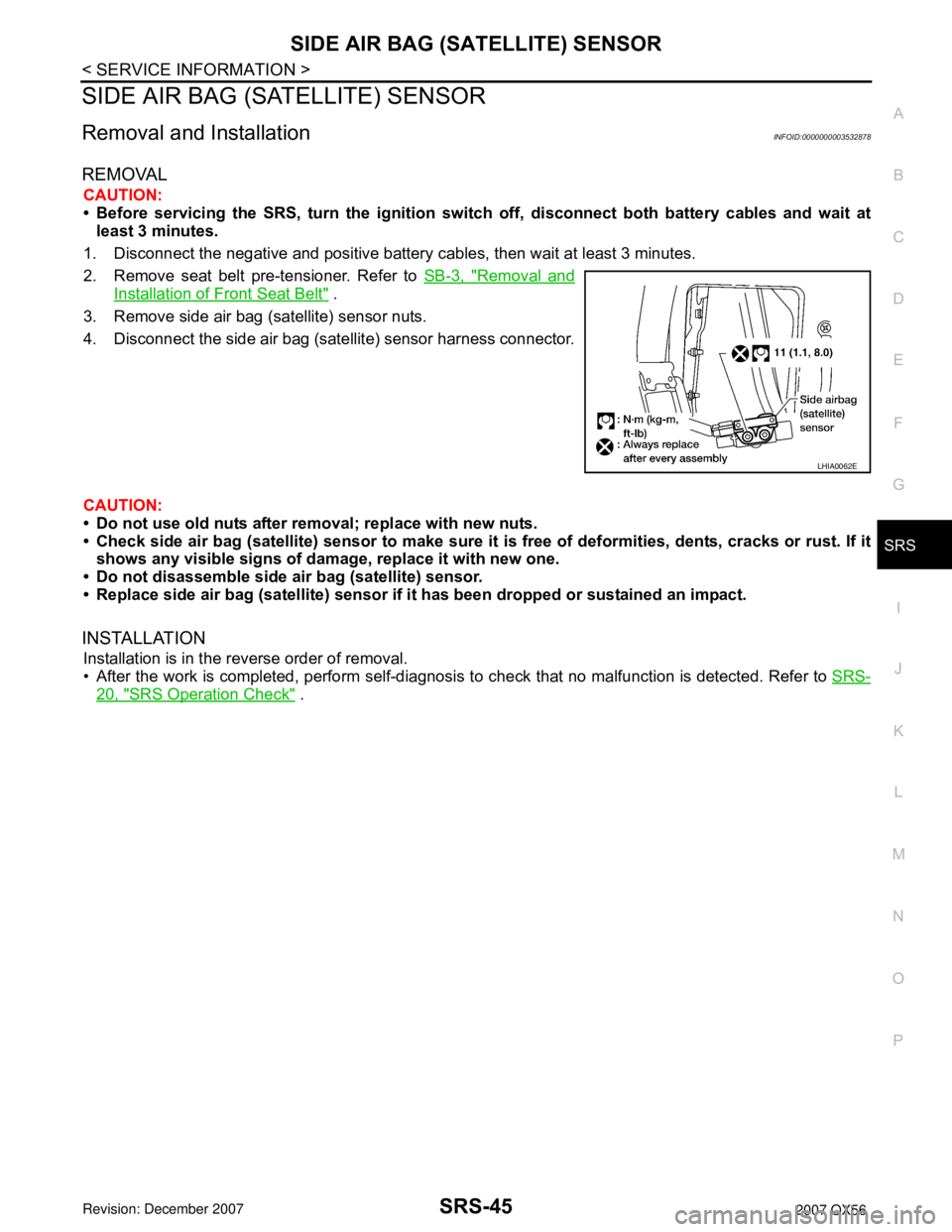
3. Remove side air bag (satellite) sensor nuts.
4. Disconnect the side air bag (satellite) sensor harness connector.
CAUTION:
• Do not use old nuts after removal; replace with new nuts.
• Check side air bag (satellite) sensor to make sure it is free of deformities, dents, cracks or rust. If it
shows any visible signs of damage, replace it with new one.
• Do not disassemble side air bag (satellite) sensor.
• Replace side air bag (satellite) sensor if it has been dropped or sustained an impact.
INSTALLATION
Installation is in the reverse order of removal.
• After the work is completed, perform self-diagnosis to check that no malfunction is detected. Refer to SRS-
20, "SRS Operation Check" .
LHIA0062E
Page 2817 of 3061
DIAGNOSIS SENSOR UNIT
SRS-47
< SERVICE INFORMATION >
C
D
E
F
G
I
J
K
L
MA
B
SRS
N
O
P
DIAGNOSIS SENSOR UNIT
Removal and InstallationINFOID:0000000003532880
REMOVAL
CAUTION:
• Before servicing the SRS, turn the ignition switch off, disconnect both battery cables and wait at
least 3 minutes.
1. Disconnect the negative and positive battery cables, then wait at least 3 minutes.
2. Disconnect the harness connectors for each air bag module and seat belt pre-tensioner.
3. Remove center console. Refer to IP-10
.
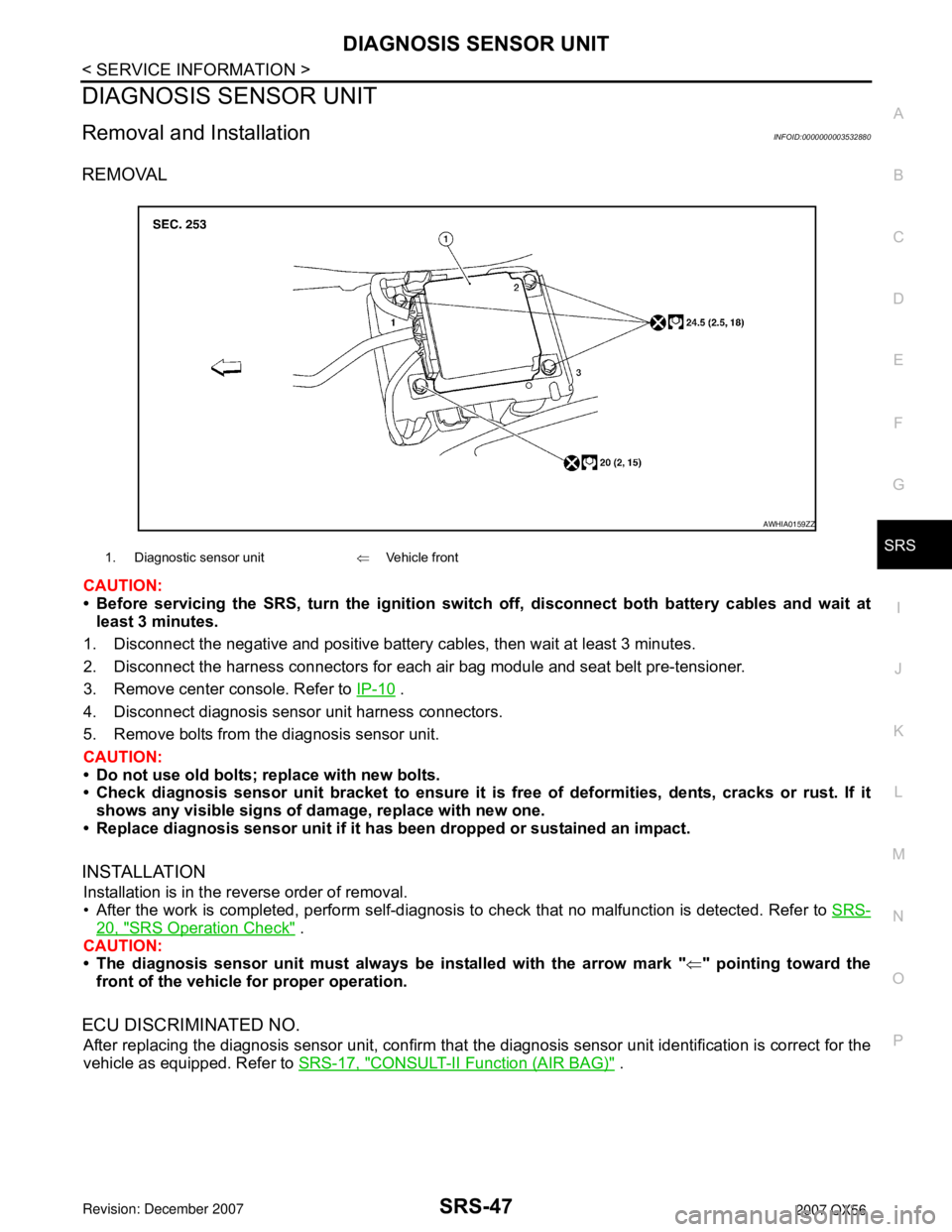
4. Disconnect diagnosis sensor unit harness connectors.
5. Remove bolts from the diagnosis sensor unit.
CAUTION:
• Do not use old bolts; replace with new bolts.
• Check diagnosis sensor unit bracket to ensure it is free of deformities, dents, cracks or rust. If it
shows any visible signs of damage, replace with new one.
• Replace diagnosis sensor unit if it has been dropped or sustained an impact.
INSTALLATION
Installation is in the reverse order of removal.
• After the work is completed, perform self-diagnosis to check that no malfunction is detected. Refer to SRS-
20, "SRS Operation Check" .
CAUTION:
• The diagnosis sensor unit must always be installed with the arrow mark "⇐" pointing toward the
front of the vehicle for proper operation.
ECU DISCRIMINATED NO.
After replacing the diagnosis sensor unit, confirm that the diagnosis sensor unit identification is correct for the
vehicle as equipped. Refer to SRS-17, "
CONSULT-II Function (AIR BAG)" .
1. Diagnostic sensor unit⇐Vehicle front
AWHIA0159ZZ
Page 2826 of 3061
TF-4
< SERVICE INFORMATION >
PRECAUTIONS
Precaution
INFOID:0000000003532508
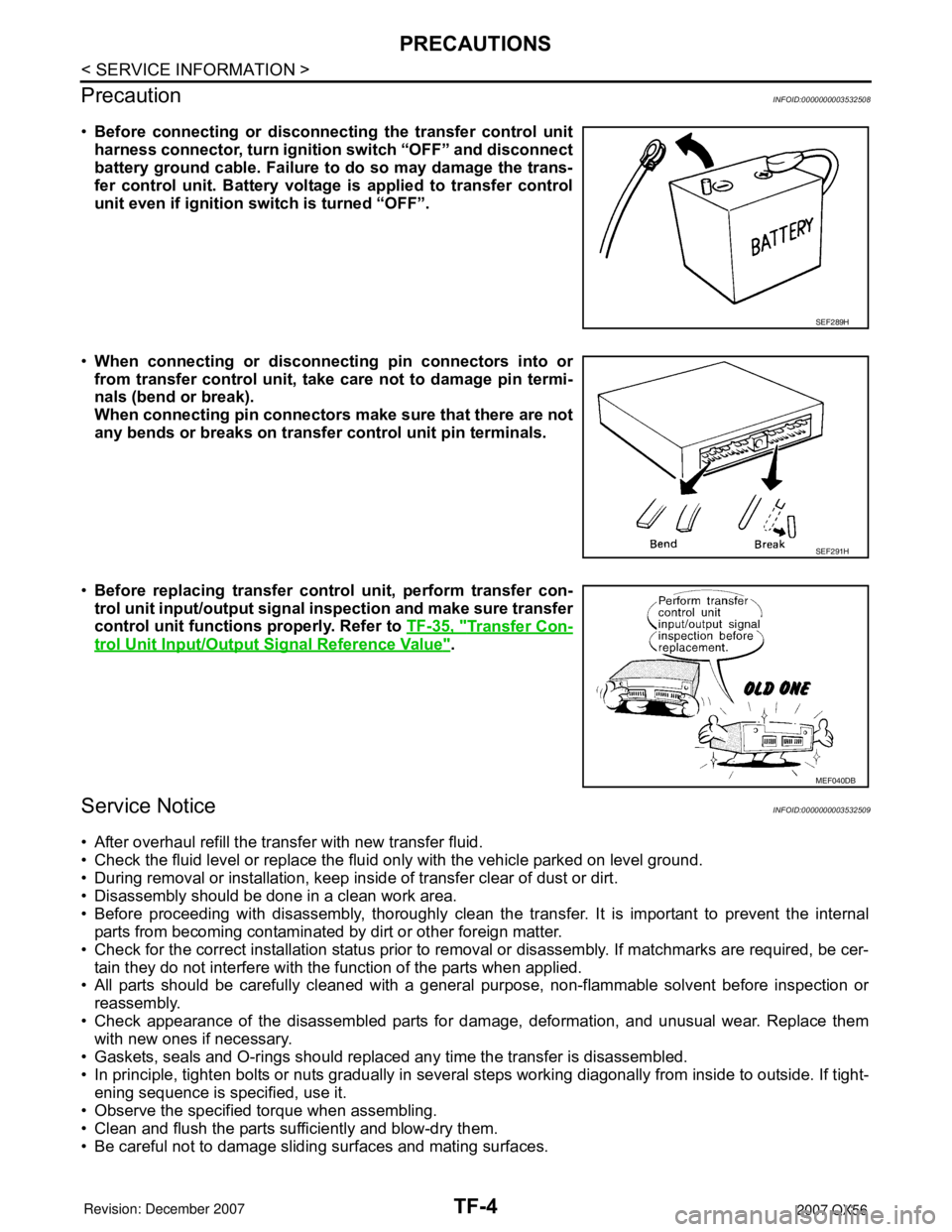
•Before connecting or disconnecting the transfer control unit
harness connector, turn ignition switch “OFF” and disconnect
battery ground cable. Failure to do so may damage the trans-
fer control unit. Battery voltage is applied to transfer control
unit even if ignition switch is turned “OFF”.
•When connecting or disconnecting pin connectors into or
from transfer control unit, take care not to damage pin termi-
nals (bend or break).
When connecting pin connectors make sure that there are not
any bends or breaks on transfer control unit pin terminals.
•Before replacing transfer control unit, perform transfer con-
trol unit input/output signal inspection and make sure transfer
control unit functions properly. Refer to TF-35, "
Transfer Con-
trol Unit Input/Output Signal Reference Value".
Service NoticeINFOID:0000000003532509
• After overhaul refill the transfer with new transfer fluid.
• Check the fluid level or replace the fluid only with the vehicle parked on level ground.
• During removal or installation, keep inside of transfer clear of dust or dirt.
• Disassembly should be done in a clean work area.
• Before proceeding with disassembly, thoroughly clean the transfer. It is important to prevent the internal
parts from becoming contaminated by dirt or other foreign matter.
• Check for the correct installation status prior to removal or disassembly. If matchmarks are required, be cer-
tain they do not interfere with the function of the parts when applied.
• All parts should be carefully cleaned with a general purpose, non-flammable solvent before inspection or
reassembly.
• Check appearance of the disassembled parts for damage, deformation, and unusual wear. Replace them
with new ones if necessary.
• Gaskets, seals and O-rings should replaced any time the transfer is disassembled.
• In principle, tighten bolts or nuts gradually in several steps working diagonally from inside to outside. If tight-
ening sequence is specified, use it.
• Observe the specified torque when assembling.
• Clean and flush the parts sufficiently and blow-dry them.
• Be careful not to damage sliding surfaces and mating surfaces.
SEF289H
SEF291H
MEF040DB
Page 2857 of 3061
TROUBLE DIAGNOSIS
TF-35
< SERVICE INFORMATION >
C
E
F
G
H
I
J
K
L
MA
B
TF
N
O
P
• Heavy tight-corner braking symptom occurs when vehicle is driven in the following conditions: 4WD shift
switch is "4H" or "4LO", steering wheel is turned fully to either side.
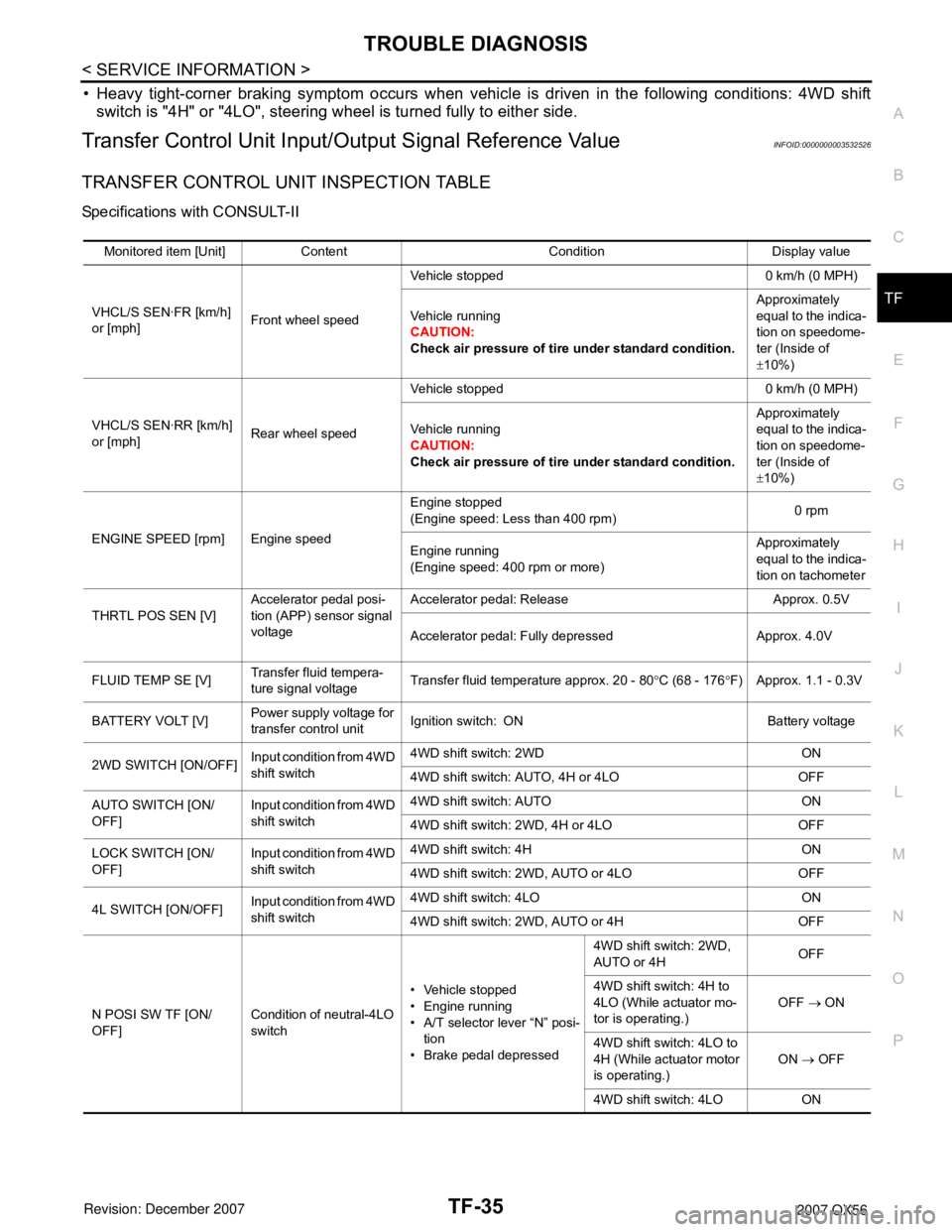
Transfer Control Unit Input/Output Signal Reference ValueINFOID:0000000003532526
TRANSFER CONTROL UNIT INSPECTION TABLE
Specifications with CONSULT-II
Monitored item [Unit] Content Condition Display value
VHCL/S SEN·FR [km/h]
or [mph]Front wheel speedVehicle stopped 0 km/h (0 MPH)
Vehicle running
CAUTION:
Check air pressure of tire under standard condition.Approximately
equal to the indica-
tion on speedome-
ter (Inside of
±10%)
VHCL/S SEN·RR [km/h]
or [mph]Rear wheel speedVehicle stopped 0 km/h (0 MPH)
Vehicle running
CAUTION:
Check air pressure of tire under standard condition.Approximately
equal to the indica-
tion on speedome-
ter (Inside of
±10%)
ENGINE SPEED [rpm] Engine speedEngine stopped
(Engine speed: Less than 400 rpm)0 rpm
Engine running
(Engine speed: 400 rpm or more)Approximately
equal to the indica-
tion on tachometer
THRTL POS SEN [V]Accelerator pedal posi-
tion (APP) sensor signal
voltageAccelerator pedal: Release Approx. 0.5V
Accelerator pedal: Fully depressed Approx. 4.0V
FLUID TEMP SE [V]Transfer fluid tempera-
ture signal voltageTransfer fluid temperature approx. 20 - 80°C (68 - 176°F) Approx. 1.1 - 0.3V
BATTERY VOLT [V]Power supply voltage for
transfer control unitIgnition switch: ON Battery voltage
2WD SWITCH [ON/OFF]Input condition from 4WD
shift switch4WD shift switch: 2WD ON
4WD shift switch: AUTO, 4H or 4LO OFF
AUTO SWITCH [ON/
OFF]Input condition from 4WD
shift switch4WD shift switch: AUTO ON
4WD shift switch: 2WD, 4H or 4LO OFF
LOCK SWITCH [ON/
OFF]Input condition from 4WD
shift switch4WD shift switch: 4H ON
4WD shift switch: 2WD, AUTO or 4LO OFF
4L SWITCH [ON/OFF]Input condition from 4WD
shift switch4WD shift switch: 4LO ON
4WD shift switch: 2WD, AUTO or 4H OFF
N POSI SW TF [ON/
OFF]Condition of neutral-4LO
switch• Vehicle stopped
• Engine running
• A/T selector lever “N” posi-
tion
• Brake pedal depressed4WD shift switch: 2WD,
AUTO or 4HOFF
4WD shift switch: 4H to
4LO (While actuator mo-
tor is operating.)OFF → ON
4WD shift switch: 4LO to
4H (While actuator motor
is operating.)ON → OFF
4WD shift switch: 4LO ON