Page 1716 of 3061
IGNITION SIGNAL
EC-633
< SERVICE INFORMATION >
C
D
E
F
G
H
I
J
K
L
MA
EC
N
P O
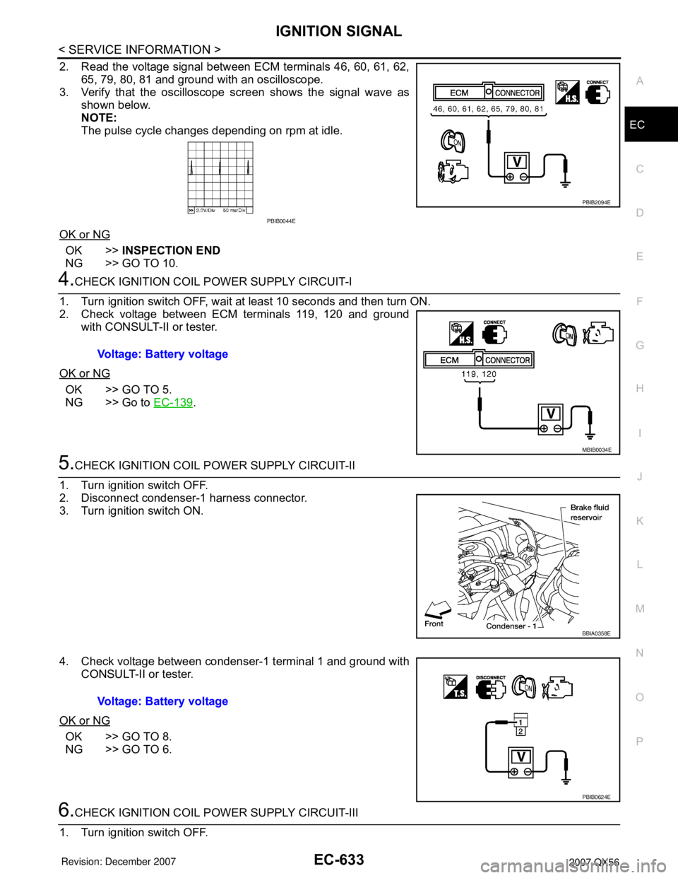
2. Read the voltage signal between ECM terminals 46, 60, 61, 62,
65, 79, 80, 81 and ground with an oscilloscope.
3. Verify that the oscilloscope screen shows the signal wave as
shown below.
NOTE:
The pulse cycle changes depending on rpm at idle.
OK or NG
OK >>INSPECTION END
NG >> GO TO 10.
4.CHECK IGNITION COIL POWER SUPPLY CIRCUIT-I
1. Turn ignition switch OFF, wait at least 10 seconds and then turn ON.
2. Check voltage between ECM terminals 119, 120 and ground
with CONSULT-II or tester.
OK or NG
OK >> GO TO 5.
NG >> Go to EC-139
.
5.CHECK IGNITION COIL POWER SUPPLY CIRCUIT-II
1. Turn ignition switch OFF.
2. Disconnect condenser-1 harness connector.
3. Turn ignition switch ON.
4. Check voltage between condenser-1 terminal 1 and ground with
CONSULT-II or tester.
OK or NG
OK >> GO TO 8.
NG >> GO TO 6.
6.CHECK IGNITION COIL POWER SUPPLY CIRCUIT-III
1. Turn ignition switch OFF.
PBIB2094E
PBIB0044E
Voltage: Battery voltage
MBIB0034E
BBIA0358E
Voltage: Battery voltage
PBIB0624E
Page 1718 of 3061
IGNITION SIGNAL
EC-635
< SERVICE INFORMATION >
C
D
E
F
G
H
I
J
K
L
MA
EC
N
P O
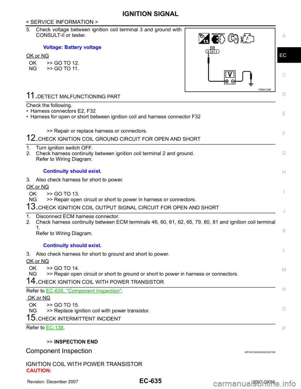
5. Check voltage between ignition coil terminal 3 and ground with
CONSULT-II or tester.
OK or NG
OK >> GO TO 12.
NG >> GO TO 11.
11 .DETECT MALFUNCTIONING PART
Check the following.
• Harness connectors E2, F32
• Harness for open or short between ignition coil and harness connector F32
>> Repair or replace harness or connectors.
12.CHECK IGNITION COIL GROUND CIRCUIT FOR OPEN AND SHORT
1. Turn ignition switch OFF.
2. Check harness continuity between ignition coil terminal 2 and ground.
Refer to Wiring Diagram.
3. Also check harness for short to power.
OK or NG
OK >> GO TO 13.
NG >> Repair open circuit or short to power in harness or connectors.
13.CHECK IGNITION COIL OUTPUT SIGNAL CIRCUIT FOR OPEN AND SHORT
1. Disconnect ECM harness connector.
2. Check harness continuity between ECM terminals 46, 60, 61, 62, 65, 79, 80, 81 and ignition coil terminal
1.
Refer to Wiring Diagram.
3. Also check harness for short to ground and short to power.
OK or NG
OK >> GO TO 14.
NG >> Repair open circuit or short to ground or short to power in harness or connectors.
14.CHECK IGNITION COIL WITH POWER TRANSISTOR
Refer to EC-635, "
Component Inspection".
OK or NG
OK >> GO TO 15.
NG >> Replace ignition coil with power transistor.
15.CHECK INTERMITTENT INCIDENT
Refer to EC-138
.
>>INSPECTION END
Component InspectionINFOID:0000000003532180
IGNITION COIL WITH POWER TRANSISTOR
CAUTION:Voltage: Battery voltage
PBIB0138E
Continuity should exist.
Continuity should exist.
Page 1728 of 3061
SERVICE DATA AND SPECIFICATIONS (SDS)
EC-645
< SERVICE INFORMATION >
C
D
E
F
G
H
I
J
K
L
MA
EC
N
P O
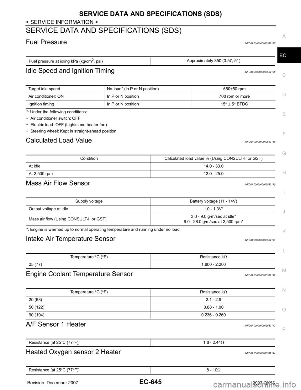
SERVICE DATA AND SPECIFICATIONS (SDS)
Fuel PressureINFOID:0000000003532187
Idle Speed and Ignition TimingINFOID:0000000003532188
*: Under the following conditions:
• Air conditioner switch: OFF
• Electric load: OFF (Lights and heater fan)
• Steering wheel: Kept in straight-ahead position
Calculated Load ValueINFOID:0000000003532189
Mass Air Flow SensorINFOID:0000000003532190
*: Engine is warmed up to normal operating temperature and running under no load.
Intake Air Temperature SensorINFOID:0000000003532191
Engine Coolant Temperature SensorINFOID:0000000003532192
A/F Sensor 1 HeaterINFOID:0000000003532193
Heated Oxygen sensor 2 HeaterINFOID:0000000003532194
Fuel pressure at idling kPa (kg/cm2, psi)Approximately 350 (3.57, 51)
Target idle speed No-load* (in P or N position) 650±50 rpm
Air conditioner: ON In P or N position 700 rpm or more
Ignition timing In P or N position 15° ± 5° BTDC
Condition Calculated load value % (Using CONSULT-II or GST)
At idle14.0 - 33.0
At 2,500 rpm12.0 - 25.0
Supply voltage Battery voltage (11 - 14V)
Output voltage at idle1.0 - 1.3V*
Mass air flow (Using CONSULT-II or GST)3.0 - 9.0 g·m/sec at idle*
9.0 - 28.0 g·m/sec at 2,500 rpm*
Temperature °C (°F) Resistance kΩ
25 (77)1.800 - 2.200
Temperature °C (°F) Resistance kΩ
20 (68)2.1 - 2.9
50 (122)0.68 - 1.00
90 (194)0.236 - 0.260
Resistance [at 25°C (77°F)] 1.8 - 2.44Ω
Resistance [at 25°C (77°F)] 8 - 10Ω
Page 1741 of 3061
EI-12
< SERVICE INFORMATION >
FRONT BUMPER
FRONT BUMPER
Removal and InstallationINFOID:0000000003533122
REMOVAL
1. Disconnect the negative battery cable.
2. Remove side screws from front fascia assembly.
3. Remove screws from front of fender protector. Refer to EI-22
.
4. Remove fog turn/fog lamp finisher and fog turn/fog lamp.
1. Lower energy absorber 2. Front bumper side bracket RH 3. Front bumper stay RH
4. Upper bumper reinforcement 5. Clip C103 6. Upper energy absorber (part of up-
per bumper reinforcement)
7. Clip CS101 8. Front fascia assembly 9. Engine undercover
10. Front fascia bracket 11. License plate bracket 12. Fog turn/fog lamp finisher LH/RH
13. Fog turn/fog lamp 14. Front bumper stay LH 15. Front bumper side bracket LH
16. Headlamp finisher (RH shown)
WIIA0952E
Page 1744 of 3061
REAR BUMPER
EI-15
< SERVICE INFORMATION >
C
D
E
F
G
H
J
K
L
MA
B
EI
N
O
P
REMOVAL
1. Disconnect the negative battery cable.
2. Remove quarter panel trim covers LH and RH.
3. Disconnect sonar sensor harness connector under rear fascia assembly.
4. Release retainer clips on both sides of rear fascia assembly with a 1/4 turn and top S clips and remove
fascia assembly.
5. Remove energy absorber.
6. Remove reinforcement assembly.
7. Remove nuts and remove retainer assembly.
• Remove S clips from retainer assembly.
8. Disconnect sonar sensors from sonar sensor retainers.
9. Remove sonar sensors and harness from rear fascia assembly.
• Disconnect sonar sensors from harness.
• Remove sonar sensor retainers from rear fascia assembly.
10. Remove bolts on each side of tow hitch and remove tow hitch.
11. Remove drafter duct from under LH quarter panel.
INSTALLATION
Installation is in the reverse order of removal.
10. Rear fascia assembly 11. Sonar sensor retainer 12. Tow hitch
13. Sonar sensor harness 14. Quarter panel trim cover RH
Page 1746 of 3061
COWL TOP
EI-17
< SERVICE INFORMATION >
C
D
E
F
G
H
J
K
L
MA
B
EI
N
O
P
COWL TOP
Removal and InstallationINFOID:0000000003533125
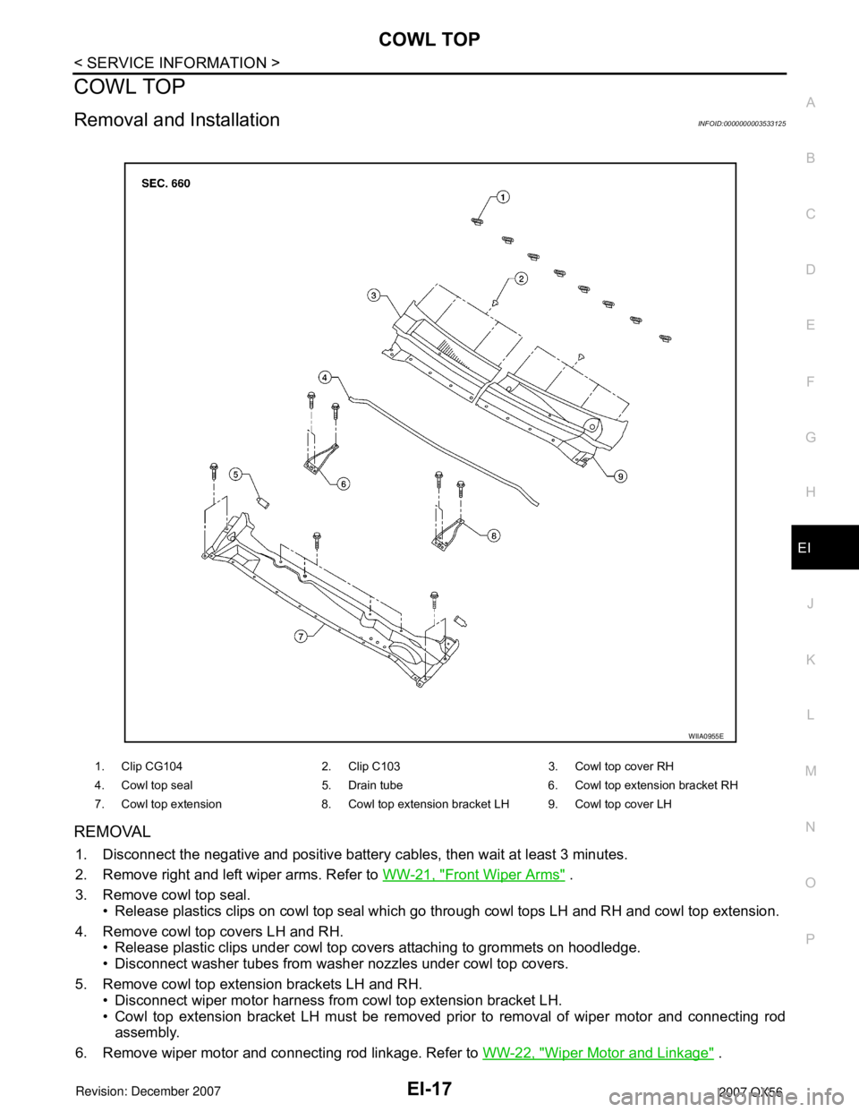
REMOVAL
1. Disconnect the negative and positive battery cables, then wait at least 3 minutes.
2. Remove right and left wiper arms. Refer to WW-21, "
Front Wiper Arms" .
3. Remove cowl top seal.
• Release plastics clips on cowl top seal which go through cowl tops LH and RH and cowl top extension.
4. Remove cowl top covers LH and RH.
• Release plastic clips under cowl top covers attaching to grommets on hoodledge.
• Disconnect washer tubes from washer nozzles under cowl top covers.
5. Remove cowl top extension brackets LH and RH.
• Disconnect wiper motor harness from cowl top extension bracket LH.
• Cowl top extension bracket LH must be removed prior to removal of wiper motor and connecting rod
assembly.
6. Remove wiper motor and connecting rod linkage. Refer to WW-22, "
Wiper Motor and Linkage" .
1. Clip CG104 2. Clip C103 3. Cowl top cover RH
4. Cowl top seal 5. Drain tube 6. Cowl top extension bracket RH
7. Cowl top extension 8. Cowl top extension bracket LH 9. Cowl top cover LH
WIIA0955E
Page 1752 of 3061
LICENSE LAMP FINISHER
EI-23
< SERVICE INFORMATION >
C
D
E
F
G
H
J
K
L
MA
B
EI
N
O
P
LICENSE LAMP FINISHER
Removal and InstallationINFOID:0000000003533129
REMOVAL
1. Disconnect the negative and positive battery cables, then wait at least 3 minutes.
2. Remove back door trim. Refer to EI-41
.
3. Disconnect harness connectors and remove with bulbs from license lamps.
4. Remove nuts and screws from license lamp finisher.
5. Release clips and remove license lamp finisher.
INSTALLATION
Installation is in the reverse order of removal.
1. Seal 2. Plastic clip 3. Nut
4. License lamp finisher 5. Clip CS101 6. Seal
WIIA0959E
Page 1754 of 3061
REAR SPOILER
EI-25
< SERVICE INFORMATION >
C
D
E
F
G
H
J
K
L
MA
B
EI
N
O
P
REAR SPOILER
Removal and InstallationINFOID:0000000003533131
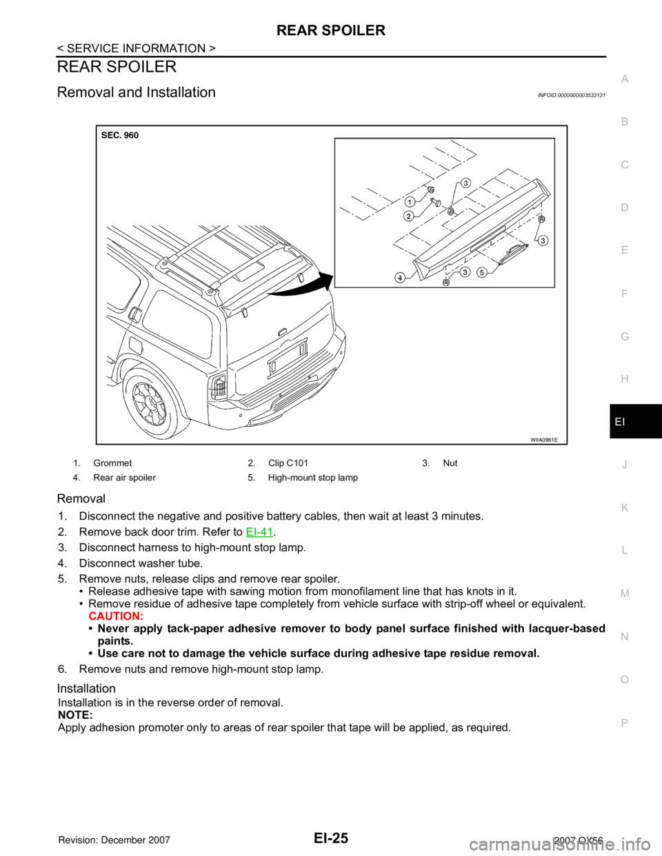
Removal
1. Disconnect the negative and positive battery cables, then wait at least 3 minutes.
2. Remove back door trim. Refer to EI-41
.
3. Disconnect harness to high-mount stop lamp.
4. Disconnect washer tube.
5. Remove nuts, release clips and remove rear spoiler.
• Release adhesive tape with sawing motion from monofilament line that has knots in it.
• Remove residue of adhesive tape completely from vehicle surface with strip-off wheel or equivalent.
CAUTION:
• Never apply tack-paper adhesive remover to body panel surface finished with lacquer-based
paints.
• Use care not to damage the vehicle surface during adhesive tape residue removal.
6. Remove nuts and remove high-mount stop lamp.
Installation
Installation is in the reverse order of removal.
NOTE:
Apply adhesion promoter only to areas of rear spoiler that tape will be applied, as required.
1. Grommet 2. Clip C101 3. Nut
4. Rear air spoiler 5. High-mount stop lamp
WIIA0961E