2007 INFINITI QX56 wiring
[x] Cancel search: wiringPage 2461 of 3061
HARNESS
PG-59
< SERVICE INFORMATION >
C
D
E
F
G
H
I
J
L
MA
B
PG
N
O
P
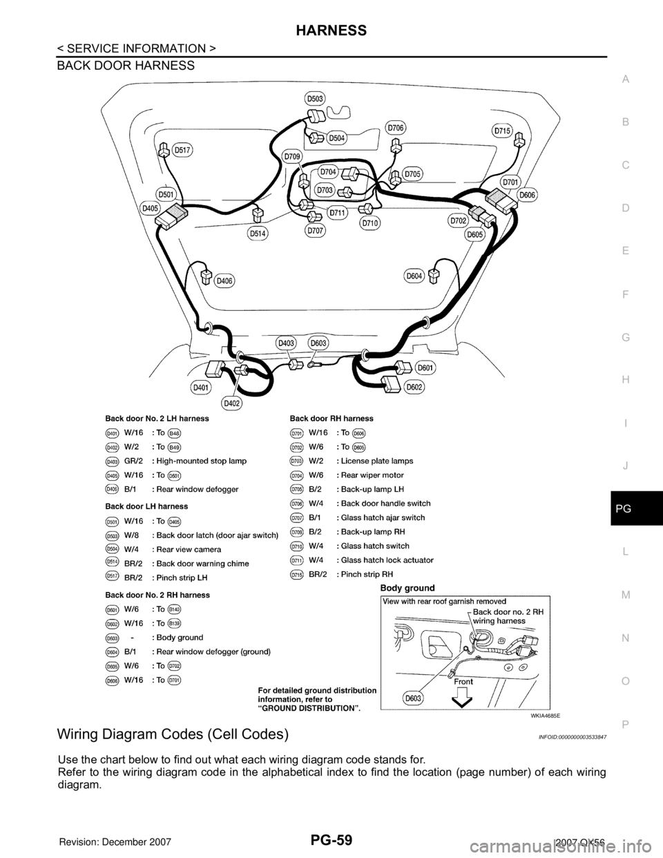
BACK DOOR HARNESS
Wiring Diagram Codes (Cell Codes)INFOID:0000000003533847
Use the chart below to find out what each wiring diagram code stands for.
Refer to the wiring diagram code in the alphabetical index to find the location (page number) of each wiring
diagram.
WKIA4685E
Page 2462 of 3061

PG-60
< SERVICE INFORMATION >
HARNESS
Code Section Wiring Diagram Name
A/C,A ATC Auto Air Conditioner
A/SUSP RSU Rear Air Suspension
AF1B1 EC Air Fuel Ratio (A/F) Sensor 1 (Bank 1)
AF1B2 EC Air Fuel Ratio (A/F) Sensor 1 (Bank 2)
AF1HB1 EC Air Fuel Ratio (A/F) Sensor 1 (Bank 1)
AF1HB2 EC Air Fuel Ratio (A/F) Sensor 1 (Bank 2)
APPS1 EC Accelerator Pedal Position Sensor
APPS2 EC Accelerator Pedal Position Sensor
APPS3 EC Accelerator Pedal Position Sensor
ASC/BS EC ASCD Brake Switch
ASC/SW EC ASCD Steering Switch
ASCBOF EC ASCD Brake Switch
ASCIND EC ASCD Indicator
A/T AT A/T Assembly
AT/IND DI A/T Indicator Lamp
AUDIO AV Audio
AUT/DP SE Automatic Drive Positioner
AUTO/L LT Auto Light Control
B/CLOS BL Back Door Auto Closure System
BACK/L LT Back-up Lamp
BRK/SW EC Brake Switch
CAN EC CAN Communication Line
CAN LAN CAN System
CHARGE SC Charging System
CHIME DI Warning Chime
CLOCK DI Clock
COOL/F EC Cooling Fan Control
COMBSW LT Combination Switch
COMM AV Audio Visual Communication System
COMPAS DI Compass and Thermometer
D/LOCK BL Power Door Lock
DEF GW Rear Window Defogger
DTRL LT Headlamp - With Daytime Light System
DVD AV DVD Entertainment System
ECM/PW EC ECM Power Supply for Back-Up
ECTS EC Engine Coolant Temperature Sensor
ETC1 EC Electric Throttle Control Function
ETC2 EC Throttle Control Motor Relay
ETC3 EC Throttle Control Motor
F/FOG LT Front Fog Lamp
F/PUMP EC Fuel Pump
FTTS EC Fuel Tank Temperature Sensor
FUELB1 EC Fuel Injection System Bank 1
FUELB2 EC Fuel Injection System Bank 2
H/AIM LT Headlamp Aiming Control
H/PHON AV Hands Free Telephone
H/LAMP LT Headlamp
HORN WW Horn
HSEAT SE Heated Seat
ICC ACS Intelligent Cruise Control
ICCBOF EC ICC Brake Switch
Page 2493 of 3061
PS-2
< SERVICE INFORMATION >
PRECAUTIONS
SERVICE INFORMATION
PRECAUTIONS
Precaution for Supplemental Restraint System (SRS) "AIR BAG" and "SEAT BELT
PRE-TENSIONER"
INFOID:0000000003532816
The Supplemental Restraint System such as “AIR BAG” and “SEAT BELT PRE-TENSIONER”, used along
with a front seat belt, helps to reduce the risk or severity of injury to the driver and front passenger for certain
types of collision. This system includes seat belt switch inputs and dual stage front air bag modules. The SRS
system uses the seat belt switches to determine the front air bag deployment, and may only deploy one front
air bag, depending on the severity of a collision and whether the front occupants are belted or unbelted.
Information necessary to service the system safely is included in the SRS and SB section of this Service Man-
ual.
WARNING:
• To avoid rendering the SRS inoperative, which could increase the risk of personal injury or death in
the event of a collision which would result in air bag inflation, all maintenance must be performed by
an authorized NISSAN/INFINITI dealer.
• Improper maintenance, including incorrect removal and installation of the SRS, can lead to personal
injury caused by unintentional activation of the system. For removal of Spiral Cable and Air Bag
Module, see the SRS section.
• Do not use electrical test equipment on any circuit related to the SRS unless instructed to in this
Service Manual. SRS wiring harnesses can be identified by yellow and/or orange harnesses or har-
ness connectors.
Precaution for Steering SystemINFOID:0000000003532817
• Before disassembly, thoroughly clean the outside of the unit.
• Disassembly should be done in a clean work area. It is important to prevent the internal parts from becoming
contaminated by dirt or other foreign matter.
• For easier and proper assembly, place disassembled parts in order on a parts rack.
• Use nylon cloth or paper towels to clean the parts; common shop rags can leave lint that might interfere with
their operation.
• Before inspection or reassembly, carefully clean all parts with a general purpose, non-flammable solvent.
• Before assembly, apply a coat of recommended Genuine NISSAN PSF or equivalent to hydraulic parts.
Petroleum jelly may be applied to O-rings and seals. Do not use any grease.
• Replace all gaskets, seals and O-rings. Avoid damaging O-rings, seals and gaskets during installation. Per-
form functional tests whenever designated.
Page 2533 of 3061
RF-1
BODY
C
D
E
F
G
H
J
K
L
M
SECTION RF
A
B
RF
N
O
P
CONTENTS
ROOF
SERVICE INFORMATION ............................2
PRECAUTIONS ...................................................2
Precaution for Supplemental Restraint System
(SRS) "AIR BAG" and "SEAT BELT PRE-TEN-
SIONER" ...................................................................
2
Precaution .................................................................2
PREPARATION ...................................................3
Special Service Tool .................................................3
Commercial Service Tool ..........................................3
SQUEAK AND RATTLE TROUBLE DIAGNO-
SIS .......................................................................
4
Work Flow .................................................................4
Generic Squeak and Rattle Troubleshooting ............6
Diagnostic Worksheet ...............................................8
SUNROOF ..........................................................10
Component Parts and Harness Connector Loca-
tion ..........................................................................
10
System Description .................................................10
CAN Communication System Description ...............11
Wiring Diagram - SROOF - ......................................12
Terminal and Reference Value for BCM ..................13
Sunroof Motor Assembly Harness Connector Ter-
minal Layout ............................................................
14
Terminal and Reference Value for Sunroof Motor
Assembly .................................................................
14
Work Flow ................................................................14
CONSULT-II Function (BCM) ..................................14
Work Support ...........................................................15
Active Test ...............................................................15
Data Monitor ............................................................15
Trouble Diagnosis Chart by Symptom .....................15
BCM Power Supply and Ground Circuit Inspection
....
16
Sunroof Switch System Inspection ..........................16
Sunroof Motor Assembly Power Supply and
Ground Circuit Inspection ........................................
16
Door Switch Check ..................................................18
Fitting Adjustment ....................................................20
Removal and Installation .........................................20
Page 2534 of 3061
RF-2
< SERVICE INFORMATION >
PRECAUTIONS
SERVICE INFORMATION
PRECAUTIONS
Precaution for Supplemental Restraint System (SRS) "AIR BAG" and "SEAT BELT
PRE-TENSIONER"
INFOID:0000000003533088
The Supplemental Restraint System such as “AIR BAG” and “SEAT BELT PRE-TENSIONER”, used along
with a front seat belt, helps to reduce the risk or severity of injury to the driver and front passenger for certain
types of collision. This system includes seat belt switch inputs and dual stage front air bag modules. The SRS
system uses the seat belt switches to determine the front air bag deployment, and may only deploy one front
air bag, depending on the severity of a collision and whether the front occupants are belted or unbelted.
Information necessary to service the system safely is included in the SRS and SB section of this Service Man-
ual.
WARNING:
• To avoid rendering the SRS inoperative, which could increase the risk of personal injury or death in
the event of a collision which would result in air bag inflation, all maintenance must be performed by
an authorized NISSAN/INFINITI dealer.
• Improper maintenance, including incorrect removal and installation of the SRS, can lead to personal
injury caused by unintentional activation of the system. For removal of Spiral Cable and Air Bag
Module, see the SRS section.
• Do not use electrical test equipment on any circuit related to the SRS unless instructed to in this
Service Manual. SRS wiring harnesses can be identified by yellow and/or orange harnesses or har-
ness connectors.
PrecautionINFOID:0000000003533089
• Disconnect both battery cables in advance.
• Never tamper with or force air bag lid open, as this may adversely affect air bag performance.
• Be careful not to scratch pad and other parts.
• When removing or disassembling any part, be careful not to damage or deform it. Protect parts which may
get in the way with cloth.
• When removing parts with a screwdriver or other tool, protect parts by wrapping them with vinyl or tape.
• Keep removed parts protected with cloth.
• If a clip is deformed or damaged, replace it.
• If an unreusable part is removed, replace it with a new one.
• Tighten bolts and nuts firmly to the specified torque.
• After re-assembly has been completed, make sure each part functions correctly.
• Remove stains in the following way.
Water-soluble stains:
Dip a soft cloth in warm water, and then squeeze it tightly. After wiping the stain, wipe with a soft dry cloth.
Oil stain:
Dissolve a synthetic detergent in warm water (density of 2 to 3% or less), dip the cloth, then clean off the stain
with the cloth. Next, dip the cloth in fresh water and squeeze it tightly. Then clean off the detergent completely.
Then wipe the area with a soft dry cloth.
• Do not use any organic solvent, such as thinner or benzine.
Page 2538 of 3061
RF-6
< SERVICE INFORMATION >
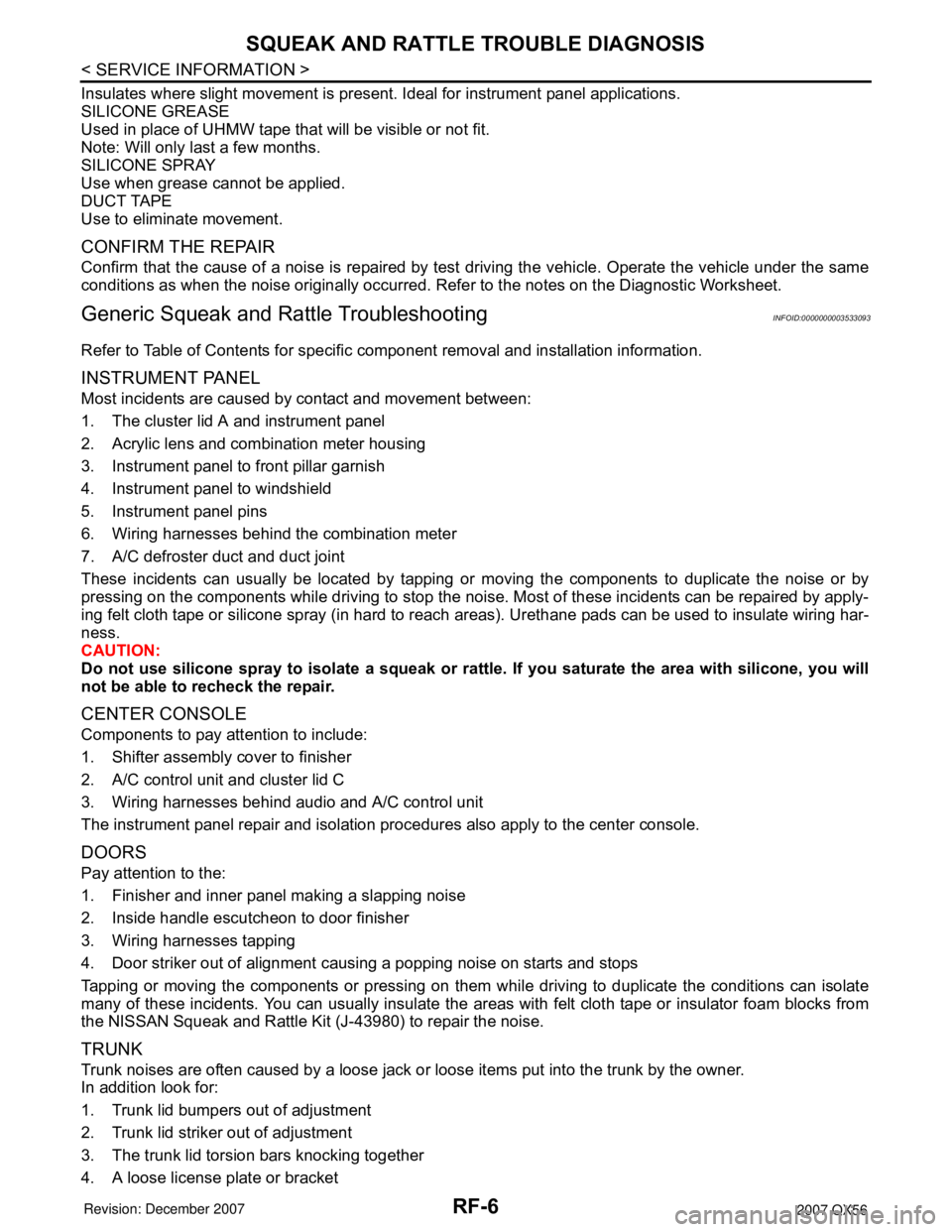
SQUEAK AND RATTLE TROUBLE DIAGNOSIS
Insulates where slight movement is present. Ideal for instrument panel applications.
SILICONE GREASE
Used in place of UHMW tape that will be visible or not fit.
Note: Will only last a few months.
SILICONE SPRAY
Use when grease cannot be applied.
DUCT TAPE
Use to eliminate movement.
CONFIRM THE REPAIR
Confirm that the cause of a noise is repaired by test driving the vehicle. Operate the vehicle under the same
conditions as when the noise originally occurred. Refer to the notes on the Diagnostic Worksheet.
Generic Squeak and Rattle TroubleshootingINFOID:0000000003533093
Refer to Table of Contents for specific component removal and installation information.
INSTRUMENT PANEL
Most incidents are caused by contact and movement between:
1. The cluster lid A and instrument panel
2. Acrylic lens and combination meter housing
3. Instrument panel to front pillar garnish
4. Instrument panel to windshield
5. Instrument panel pins
6. Wiring harnesses behind the combination meter
7. A/C defroster duct and duct joint
These incidents can usually be located by tapping or moving the components to duplicate the noise or by
pressing on the components while driving to stop the noise. Most of these incidents can be repaired by apply-
ing felt cloth tape or silicone spray (in hard to reach areas). Urethane pads can be used to insulate wiring har-
ness.
CAUTION:
Do not use silicone spray to isolate a squeak or rattle. If you saturate the area with silicone, you will
not be able to recheck the repair.
CENTER CONSOLE
Components to pay attention to include:
1. Shifter assembly cover to finisher
2. A/C control unit and cluster lid C
3. Wiring harnesses behind audio and A/C control unit
The instrument panel repair and isolation procedures also apply to the center console.
DOORS
Pay attention to the:
1. Finisher and inner panel making a slapping noise
2. Inside handle escutcheon to door finisher
3. Wiring harnesses tapping
4. Door striker out of alignment causing a popping noise on starts and stops
Tapping or moving the components or pressing on them while driving to duplicate the conditions can isolate
many of these incidents. You can usually insulate the areas with felt cloth tape or insulator foam blocks from
the NISSAN Squeak and Rattle Kit (J-43980) to repair the noise.
TRUNK
Trunk noises are often caused by a loose jack or loose items put into the trunk by the owner.
In addition look for:
1. Trunk lid bumpers out of adjustment
2. Trunk lid striker out of adjustment
3. The trunk lid torsion bars knocking together
4. A loose license plate or bracket
Page 2544 of 3061
RF-12
< SERVICE INFORMATION >
SUNROOF
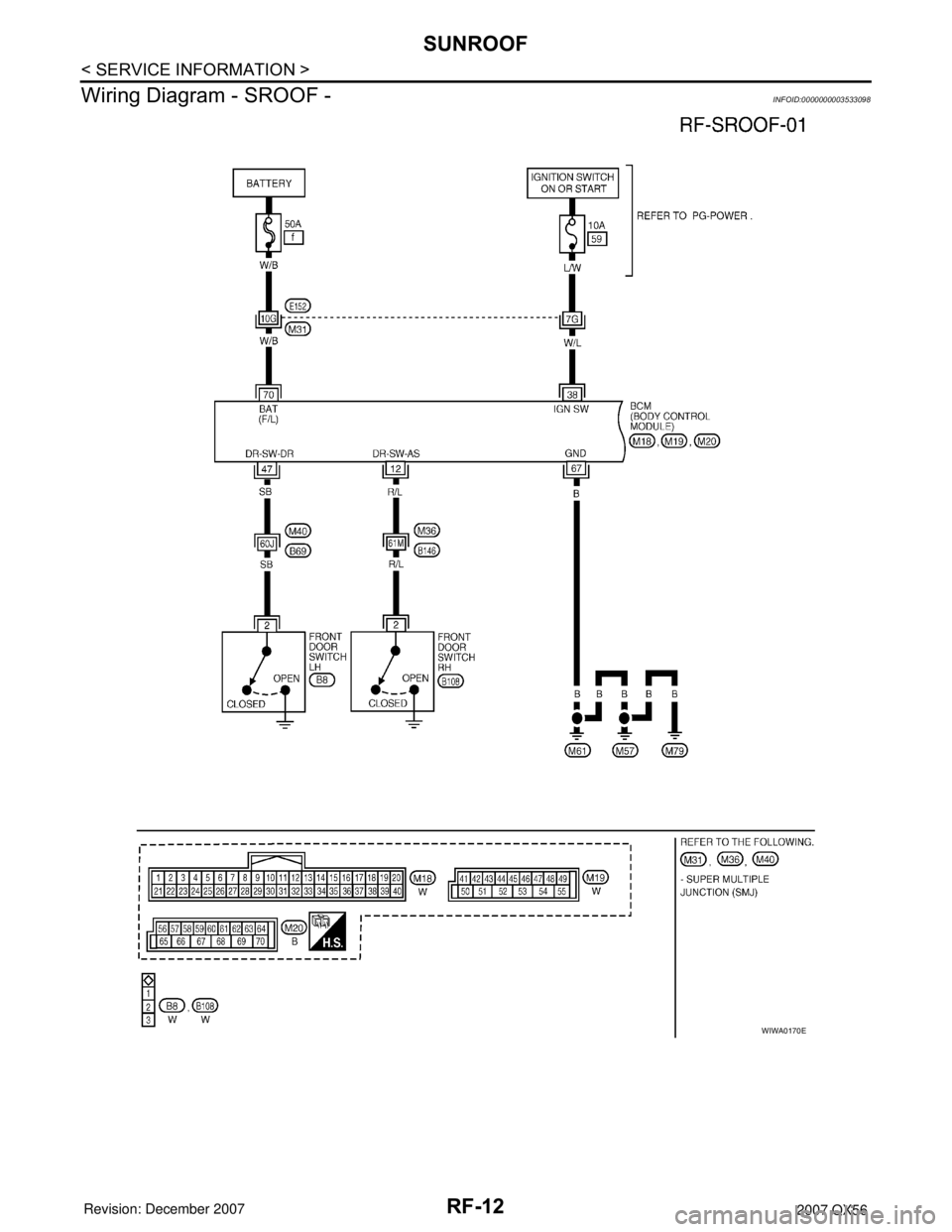
Wiring Diagram - SROOF -
INFOID:0000000003533098
WIWA0170E
Page 2591 of 3061
RSU-1
SUSPENSION
C
D
F
G
H
I
J
K
L
M
SECTION RSU
A
B
RSU
N
O
PCONTENTS
REAR SUSPENSION
SERVICE INFORMATION ............................2
PRECAUTIONS ...................................................2
Precaution for Supplemental Restraint System
(SRS) "AIR BAG" and "SEAT BELT PRE-TEN-
SIONER" ...................................................................
2
Precaution for Rear Suspension ...............................2
PREPARATION ...................................................3
Commercial Service Tool ..........................................3
NOISE, VIBRATION AND HARSHNESS
(NVH) TROUBLESHOOTING .............................
4
NVH Troubleshooting Chart ......................................4
CAN COMMUNICATION .....................................5
System Description ...................................................5
TROUBLE DIAGNOSIS ......................................6
How to Perform Trouble Diagnosis for Quick and
Accurate Repair ........................................................
6
Component Parts and Harness Connector Loca-
tion ............................................................................
8
Wiring Diagram - A/SUSP - .......................................9
Basic Inspection ......................................................10
Chek Suspension Indicator Lamp Timing ...............11
Control Unit Input/Output Signal Standard ..............11
CONSULT-II Function (AIR LEVELIZER) ...............11
TROUBLE DIAGNOSIS FOR SELF-DIAG-
NOSTIC ITEMS ..................................................
14
Height Sensor System Inspection ...........................14
Exhaust Valve Solenoid System Inspection ............15
Compressor Motor, Compressor Motor Relay and
Circuit Inspection .....................................................
17
TROUBLE DIAGNOSES FOR SYMPTOMS ......19
Load Leveling Rear Air Suspension System Does
Not Operate .............................................................
19
Chek Suspension Indicator Lamp Stays On When
Ignition Switch Is Turned On ...................................
20
REAR SUSPENSION ASSEMBLY ...................21
Component ..............................................................21
On-Vehicle Inspection and Service .........................22
Wheel AlignmentInspection .....................................23
REAR SUSPENSION MEMBER .......................26
Removal and Installation .........................................26
SHOCK ABSORBER ........................................30
Removal and Installation .........................................30
SUSPENSION ARM ..........................................31
Removal and Installation .........................................31
FRONT LOWER LINK .......................................33
Removal and Installation .........................................33
REAR LOWER LINK & COIL SPRING .............35
Removal and Installation .........................................35
STABILIZER BAR .............................................37
Removal and Installation .........................................37
REAR LOAD LEVELING AIR SUSPENSION
COMPRESSOR ASSEMBLY ............................
38
Removal and Installation .........................................38
HEIGHT SENSOR .............................................40
Removal and Installation .........................................40
CONTROL UNIT ................................................42
Removal and Installation .........................................42
Initialization Procedure ............................................42
SERVICE DATA AND SPECIFICATIONS
(SDS) .................................................................
43
Wheel Alignment .....................................................43
Ball Joint ..................................................................43
Wheelarch Height (Unladen*1) ................................44